| On this page |
Overview 
Houdini uses a mathematical pinhole camera to simulate a camera. Because a pinhole camera does not have in-camera effects such as depth of field and bokeh, you must be explicitly tell mantra to simulate them (see below).
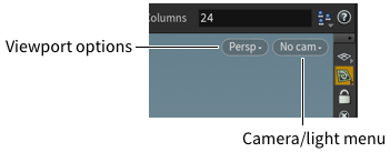
Current view vs cameras 
Unlike some other packages, Houdini’s viewport view does not necessarily correspond to a camera. You can lock the viewport to a camera (so changing the view moves/reorients the camera), but normally the current view in the viewport is separate from any cameras. There are also many options to render the current view without creating a camera.
How to 
| To... | Do this |
|---|---|
|
Create a camera/light |
On the shelf, click the Lights and Cameras tab.
|
|
Look through a camera/light |
Choose the camera from the camera menu.
|
|
Lock a camera/light to the viewer |
Tip By default, the view is exported to the camera or light when the mouse button is released. This behavior can be overridden by turning on Export View Continuously in the camera menu. This option should be used with caution as exporting the view can trigger cooking. |
|
Set depth of field |
See Depth of Field. |
Motion blur 
There are three types of blur.
Transformation blur blurs moving objects overall.
To blur the moving pieces of deforming geometry, there are two options.
Velocity blur uses the v velocity attribute on points in deforming geometry. This requires that the velocity attribute exist on the geometry. Since the attribute is not recalculated at each sub-frame, this method cannot blur deformation along a curve. This method works even if the topology of the geometry changes between frames (as with particle systems, where new points may be born or die between frames).
Geometry blur sends separate copies of the geometry to mantra for each sub-frame. This requires that the topology of the geometry does not change between frames. Since this method requires sending multiple copies of the geometry to mantra, it is necessarily slower.
Tip
Motion is evaluated at sub-frame intervals. If you use expressions to animate objects or deformations, you should use $T (floating point time) in the expressions instead of $F (integer frame number). Expressions that use $F will not show motion blur properly (since the expression will give the same result at every sub-frame).
| To... | Do this |
|---|---|
|
Turn on motion blur |
In the parameter editor for the render node, go to the Properties ▸ Sampling sub-tab and turn on Allow motion blur. This enables transform motion blur for all objects. To enable motion blur on individual objects, add the Allow motion blur property to the object and turn it on there, instead of on the render node. |
|
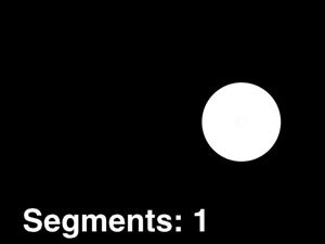
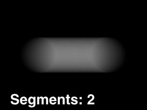
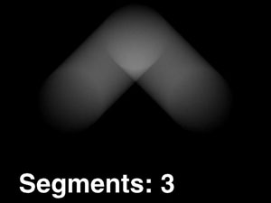
Increase transform motion blur quality |
In the parameter editor for the render node, go to the Properties ▸ Sampling sub-tab and increase the Xform Time Samples parameter. This blends between more sub-frame positions, giving more accurate but slower rendering of objects moving along a curve.
|
|
Turn on velocity blur for an object |
|
|
Turn on geometry blur for an object |
|
|
Use motion blur with volumes |
Volume shaders will recognize the |
See the parameter descriptions on the ![]() mantra render node for more information.
mantra render node for more information.
Depth of field 
| To... | Do this |
|---|---|
|
Turn on depth of field |
You can turn on depth of field by turning on Enable Depth of Field on the Sampling sub-tab of the Properties tab in the parameter editor of a render node. |
|
Control depth of field |
There are four parameters that control depth of field. The Focal Length parameter is on the View tab of the camera node. The Focus Distance, F-Stop, and Bokeh parameters are on the Sampling tab of the camera node. Focal Length Camera focal length (zoom). Focus Distance The lens focal distance and distance from the camera at which objects will be in focus. If the fstop channel is also used, objects outside this distance will be blurred. F-Stop Determines blurriness of depth-of field effects. |
|
Control optimized rendering of blurred imagery |
The Motion Factor parameter on the render node can be used with extreme depth of field. This allows you to decrease the Shading Quality based on how blurred the object is. Objects that are not out of focus will have their specified shading quality. Objects that are heavily out of focus will have their shading quality decreased. This will affect render times with little perceptual loss in image quality. |
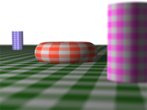
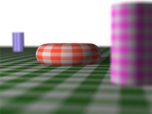
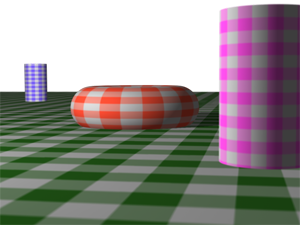
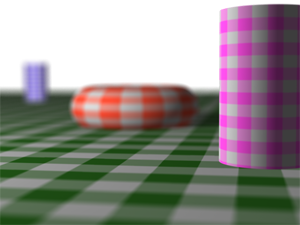
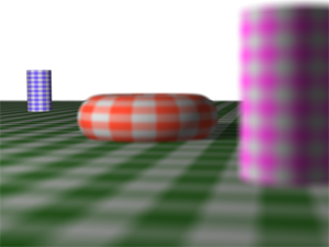
F-stop 
The following images show the effect of changing F-Stop. The Focus Distance is set at 12, and the Focal Length is set at 200mm.
F-stop |
Result |
|---|---|
1.3 |
|
0.8 |
|
5.0 |
|
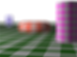
Focus 
The following images show the effect of changing the focus. The Focal Length is set at 200mm, and the F-Stop is set at 1.
Focal distance |
Result |
|---|---|
7 |
|
20 |
|
3 |
|
Bokeh 
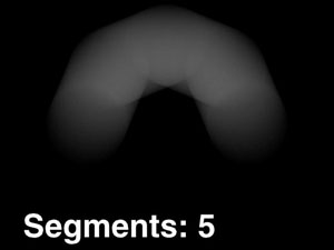
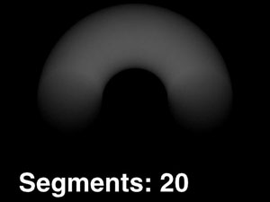
Bokeh simulates how different lenses, apertures, and reflections inside the camera body affect how elements blur outside the depth of field. It makes bright points in the out-of-focus background appear as large transparent discs, boxes, or hexagons (depending on the camera).
Mantra lets you use radial (circular) or box bokeh, or specify an image representing the shape to use for blurred bright spots.
To control bokeh on a camera:
-
Select the
 camera object.
 -
In the parameter editor, click the Sampling tab.
-
Use the bokeh parameters to control the look of the out of focus elements.
When specifying a bokeh image, it should be a gray scale image where white pixels are the shape and black pixels are the background. (You can use a color image, but mantra will automatically convert it to gray scale.)
Overlay geometry on the camera view 
This is useful for overlaying information, for example to display a slate over top of the view for flipbooking. This does not actually gate or gobo the camera/light, it only affects the viewer.
-
Create a geometry (SOP) network to generate the graphics.
Houdini scales the portion of the mask geometry between 0 and +1 X and Y to the viewport size to create the overlay.
-
Create a camera and choose Edit Rendering Parameters from the
 gear drop-down menu.
 -
In the Edit Parameter Interface window, expand the Viewport Display folder, select the View Mask folder, and click the
 add arrow. This will add the View Mask tab to the parameter editor.
 -
In the
camera node's parameter editor, click the View Mask tab. -
Set the Mask aspect to control the gating of the view.
-
Set the Mask opacity.
-
If you created overlay geometry, click the + button next to the Mask overlay SOP parameter and choose the node containing the overlay geometry.
-
To see the overlay, look through the camera or light, and turn on Camera mask on the __Guides tab of the display options window.
Tips and Tricks 
-
To make the camera appear to shake during an animation, try these expressions in the camera’s Translate-Z parameter:
Shake on 2s
if($F%2, 1, -1) * easeout()Shake on 4s
if( $F/2%2, if($F%2, 1, 0.5), if($F%2, -1, -0.5) ) * easeout()