| On this page |
|
Overview 
The ![]() Layout LOP node has a brushing mode that lets you interactively populate the scene with point instanced models (for example, trees, bushes, rocks, buildings). How the node translates mouse events into creating instances is controlled by a brush asset. You can create your own brush asset that provides custom behavior defined by a SOP network.
Layout LOP node has a brushing mode that lets you interactively populate the scene with point instanced models (for example, trees, bushes, rocks, buildings). How the node translates mouse events into creating instances is controlled by a brush asset. You can create your own brush asset that provides custom behavior defined by a SOP network.
Since the brush’s behavior is defined by a compiled SOP block, you can use the full power of (compile-able) SOPs, including curve and polygon manipulation nodes, scatter nodes, and VEX code in wrangles.
You can give the brush asset a parameter interface. This interface is displayed in the Layout UI when your brush is active. This lets you give your uses controls to customize your brush’s behavior.
Before you implement a brush, you should probably be familiar with the following subjects:
-
Compiled blocks. The implementation of the brush is inside a compiled block (so it can be invoked by the parent Layout node with high performance). There are limitations to what SOP nodes you can use inside a compiled block, as well as limitations on expressions that cause nodes to cook.
-
Wrangle nodes and VEX snippets. Often the easiest way to implement some behavior is to use an
 Attribute Wrangle to read attributes, compute values, and write new attributes. However, this requires some knowledge of VEX snippets and the built-in VEX functions.
Terms 
Stroke
The user presses down a mouse button, moves the mouse, and releases the mouse button.
Invocation
One run of the compiled block in the brush SOP network. The compiled block is invoked many times during a stroke.
Tracking points
Points generated by projecting from the pointer down onto the stage plane/surface during a stroke.
Model
In this documentation, we’ll refer to the USD models you can instance onto points as models. This is an attempt to avoid confusion over the word asset, which will usually refer to the brush digital asset node.
Working set
Brushes are essentially plugins for the Layout node, to customize how mouse clicks, drags, and so on are interpreted in the Layout state. As part of the Layout interface, the user builds a “working set” of the USD models they want to be instancing.
In the brush network, the working set is represented by a set of points and matching bounding box packed primitives in the sixth (Working Set) input, where the point number is the number you use to instance that model onto points, and other attributes on the points encode basic information about the models such as their bounding boxes.
It’s up to the brush to decide how/whether to instance the various models in the working set (see using the working set below).
Making a new custom brush 
| To... | Do this |
|---|---|
|
Start a new brush asset |
In the Layout node UI, click the New Brush option in the gear menu of the Brushes section. This opens the dialog for creating a new digital asset. You can specify the asset namespace, name, and save location. See creating a new digital asset for more information. When you create a new brush asset using this button, it populates the asset with boilerplate nodes, sticky notes, and boilerplate Python code to make it easier to implement the brush. It also sets the new asset up so it’s automatically discovered as a new brush by the Layout node. |
|
Edit a brush asset |
To edit the network, parameter interface, or Python scripts of a brush asset it is highly recommended you press the “Debug Brush” button in the operator bar of the Layout LOP state and draw an example stroke in the viewport. This will create a SOP network that tries its best to emulate the layout state. Doing so will allow much faster iteration and easier debugging. If you would like to edit the brush inside of the layout node, right click the brushes icon and press Edit Network. |
Tip
The Layout node looks for assets with a section named layout_brush to build the list of available brushes. If for some reason you are creating a brush asset from scratch instead of copying the template, you must remember to add this section in the Extra Files tab of your asset.
Inside the SOP network 
-
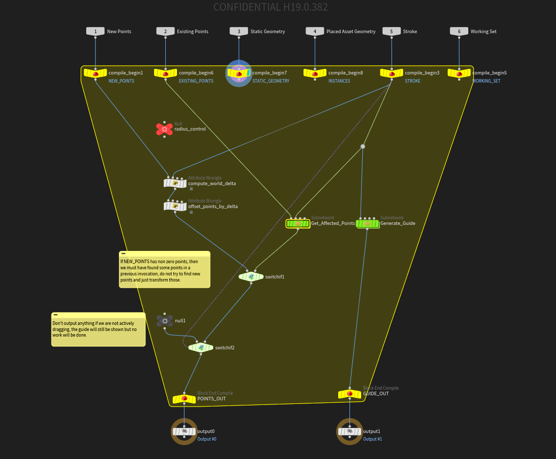
A brush is a SOP asset with six inputs and two outputs. A brush can create new points, or modify/delete existing points.
-
Within the network is a compiled block that is repeatedly invoked as the user moves the mouse.
-
The compiled block inputs contain information from the layout LOP about the current state and what the user has done.
-
The compiled block is invoked even when the user is just moving the mouse around, before they begin a stroke. This allows you to display guides and preview.
Switch If|Node:sop/switchif] nodes are useful to control behaviour specific to certain mouse actions, for example, only outputting points when the user is dragging the mouse.
-
The layout brush convention to represent transforms are the same
pscaleandorientattributes output by many common SOPs like the Scatter and Align SOP.
Note
Authoring other instance attributes may cause odd behaviour as some will override all
pscaleandorientattributes for all current and previously authored points. -
Outputting custom point attributes will create primitive attributes on the resulting instances for all authored points. Be careful not to introduce a large amount of attributes as it may hinder performance.
-
To instance a model from the working set onto a point, do the following:
-
Set the point’s
asset_indexattribute to the point number of the point in the sixth (Working Set) input corresponding to the model you want to instance.
-
-
To modify a point (from either the “new” or “existing” inputs), do the following:
-
To set the position of a point, set the
Pvector3point attribute. -
To set the orientation and scale of the instanced model on a point, you have to encode the rotations and scales into a
matrix3point attribute calledtransform.You can easily set/edit a
transformattribute using a Transform SOP. Add the Transofrm node to the network, set the Rotate and Scale parameters on the node to the values you want, and set the Attributes parameter totransformto write the transformations into the attribute. -
Send any modified points to the the first output.
If you modify an existing point, it will be deleted and an identical new point will be added to the first (New Points) input on the next invocation. So any existing points you edit with a stroke become part of the stroke’s “new” points.
Note
To scale/rotate instances, you must encode them in the standard
orientvector4andpscale`float attributes. Using other instancing attributes may override these and cause undue effects. -
-
If you haven’t modified existing points, you shouldn’t send them to the output (the output always represents the new set of “new points” created by the current stroke). If your brush doesn’t affect existing points, you don’t need to wire the second input into anything at all.
-
To delete an existing point, create a
deletepoint attribute on the point and set it to1. Then merge the point into the first output.To delete a point from the current stroke (the first (New Points) input), just don’t send it down to the output.
Inputs 
Label |
Description |
|---|---|
1. New Points |
All the points added by earlier invocations during the current stroke. If you want to keep any of these points (that is, instantiate models onto them), wire the points into the first output. Any points from the first input that don’t make it down to the output are thrown away. |
2. Existing Points |
All points created in previous operations by any brush. These are the point instances currently committed into the scene. You can modify these points by changing their attributes in the SOP network. If the network modifies the attributes on a point in the second (Existing Points) input, the parent Layout node actually deletes the point from the “Existing” list and adds the point (with the modifications) to the first (New Points) input. To delete existing points, set an integer point attribute named |
3. Static Geometry |
This is “collision” geometry wired into the Layout node by the user. This is often “ground” geometry the user wants to place assets on. You can use this when creating extra points. For example, as the input to |
4. Asset Geometry |
The geometry of all the instances created by this node (that is, the output of instancing models onto the existing points). You can use this when creating extra points. For example, as the input to |
5. Stroke |
Contains a polyline primitive, where the points represent intersections between the mouse ray and the current scene. There are also global (detail) attributes on the input that encode information about the current state, for example whether the user is holding the ⇧ Shift key. You can use these to allow the user to vary or customize the brush behavior with modifier keys.
See stroke attributes below for a list of attributes available on the stroke. |
6. Working Set |
Encodes each item in the Layout node’s working set (the models to be instantiated) as a disconnected point and associated bounding box packed primitive. To instance a model, set a new point’s See the working set attributes below for a list of other attributes available on these points. |
Outputs 
Label |
Description |
|---|---|
1. Output Points |
For each invocation, this contains the set of points you want to instance onto. Any points you output here are passed as the first (New Points) input in the next invocation. Similar to merge |
2. Guides |
Guide geometry to draw over the instanced output. This lets you give the user visual feedback. For example, if your brush scatters models within a certain radius of the mouse pointer, you can draw a ring guide showing the limit of the scatter area. In the brush asset’s Python module you can implement the If the |
Stroke input attributes 
Global (detail) attributes 
Nmae |
Type |
Description |
|---|---|---|
|
|
The mouse button is being held down ( |
|
|
This is the start of a drag ( |
|
|
The user is moving the mouse without dragging ( |
|
|
The user clicked ( |
|
|
This is the end of a drag ( |
|
|
|
|
|
|
|
|
|
|
|
The Caps Lock key is being pressed ( |
|
|
The ⌃ Ctrl key (or command key on Mac) is being pressed ( |
|
|
The ⇧ Shift key is being pressed ( |
|
|
The Alt key (option key on Mac) is being pressed,( |
|
|
Contains a number which changes for each click/stroke, but stays the same across the entire stroke. This is useful to use as a seed value for random values that you want to be consistent across the stroke. |
|
|
A transformation matrix to map from screen space to world space. This is useful when implementing a brush that works in screen space. |
|
|
A vector describing the up vector metadata on the stage input into the layout node. |
Point attributes on the stroke polyline 
A polyline in the 5th input represents the user’s interactive stroke. Each point on the polyline represents a sample taken along the stroke. Each point has several attributes storing data about the sampled intersection.
As the user “draws” in the viewport, the node fires rays “into” the screen to find what the pointer is over in 3D space.
By default, the Layout node finds the nearest intersection with existing instances, the static (often “ground”) geometry, and the XZ ground plane. (Note that the user can set an option when using the Layout node to not intersect static geometry or not intersect existing instances.)
If a ray doesn’t intersect anything, the network is still invoked, but the new point in the Stroke input is simply a copy of the previous valid point.
Name |
Type |
Description |
|---|---|---|
|
|
The (intersected) position in 3D space. |
|
|
The normal at the intersected point. |
|
|
The origin of the intersecting ray in 3D space (derived from the screen coordinates of the mouse pointer). This is useful to make a brush that works in screen space. |
|
|
The direction of the intersecting ray in 3D space (from the mouse pointer “forward” into the scene, following the camera projection). |
|
|
Horizontal position of the mouse pointer, in screen pixels. |
|
|
Vertical position of the mouse pointer, in screen pixels. |
|
|
If the mouse pointer was over an instanced model, this value is the point number of the instance, from the second (Existing points) input. For example, you could make a brush that deletes any instances you drag over, by checking the contents of this attribute and preventing the point from being output. Or, you could make a brush that pushes/nudges existing instances. If a stroke starts on an instance, you could then use subsequent points in the stroke to translate that instance’s point. |
|
|
Angle of the tablet pen, if the stroke was created using a tablet or similar device. |
|
|
Pressure of the tablet pen, if the stroke was created using a tablet or similar device. |
Working Set input point attributes 
Each point in the sixth (Working Set) input corresponds to an item currently in the Layout node’s working set.
|
|
The same as the point number. This is the value you should set the |
|
|
The size of the bounding box of the model corresponding to this point. |
|
|
The center of the bounding box. |
The bounding box attributes can be useful to space out instances to prevent intersections when scattering, and/or to show footprint or bounding box guides. Note that each point has the assets bounding box as a packed primitive at the same index.
See using the working set for more information.
Multi-stroke brush 
-
Normally, on the mouse up event at the end of a stroke, the point output of the brush’s compiled block is “committed” and integrated into the Layout node’s point instance data.
-
If necessary, you can implement a brush that allows the user to make multiple strokes as part of one operation.
For example, you could implement a fence-drawing brush where each click/drag makes a new corner in the fence until the user closes the fence by connecting back to the start (or until the user presses Enter to leave the fence open).
You could also use a multi-stroke interaction to let the user draw rectangles, where one stroke defines the length of one side, and then a second drag pulls out the length of the adjecent side.
-
To indicate to the parent Layout node that the current operation should continue after the current stroke, add a
end_strokedetail attribute to the first output, set to0.The Layout node sees that the attribute exists and keeps the current operation active. Subsequent strokes will keep appending to the same list of “existing points”.
-
Then, to indicate to the parent Layout that the current operation is finished, set the
end_strokedetail attribute on the first output to1.In the fence making example, you would use an
 Attribute Create node to create the
 end_strokeinteger detail attribute, and connect it to the first output. You could then use an expression or Attribute Wrangle to set the attribute to1if the end of the current stroke is near the starting point or the first stroke, or0otherwise.The layout node sees
end_strokeexists but is set to1, and commits the output. -
The user can always press Enter to finish and commit the current operation.
-
Implementing a multi-stroke brush is more complex, but there are a couple of techniques that can help you
-
Use a series of
 Switch If nodes to switch to individual branches that handle each of the different event types.
 -
If you need to pass information between invocations and/or strokes, you can set your own custom detail attributes on the first output. The detail attributes from the first output will be copied back into the first (New Points) input, until the operation is committed.
In the example of drawing a rectangle, you could use a detail attribute to keep track of whether the current stroke is the first or second stroke of the operation.
-
Operation commit 
When the user finishes an operation:
-
The Layout node clears any detail attributes added to the output geometry.
Detail attributes you create on the output geometry become available as detail attributes on the first (New Points) input on the next iteration. If you use these detail attributes on the to communicate information between iterations (or strokes in a multi-stroke brush), the information will not carry over between operations.
-
The Layout node also clears any primitives generated by the brush as a precaution.
Since there is a lot of merging of point clouds, if primitives are involved the primitive merging quickly becomes exponential and will lock up Houdini.
Parameter interface 
You can design a parameter interface for the brush, and in the compiled block, use a ch expression to read the value of a parameter and use it to change how the brush works.
For example, you could have a Density parameter (internal name density) on the brush asset to control how many points the brush scatters as the user drags. Inside the compile block, for example in the Force Total Count parameter of a ![]() Scatter SOP, you can use the expression
Scatter SOP, you can use the expression ch("../density") to copy the parameter value.
When a brush is active in the Layout LOP, the layout interface shows the brush parameters, the same as they would appear in a parameter editor.
Scroll wheel 
There are two ways to allow the user to use the scroll wheel to change how your brush behaves.
-
If your brush’s parameter interface has a parameter whose internal name starts with
scroll, that parameter will be incremented/decremented when the user scrolls the mouse wheel. (If more than one parameter starts withscroll, the node will change them all.) -
If you implement an
onMouseWheelEvent(kwargs)function in the asset’s Python module, the Layout state will call it when the user scrolls the mouse wheel.
Brush Resizing 
The convention for resizing the radius (or similar attributes) of a brush is ⌃ Ctrl + ⇧ Shift + ![]() similar to Attribute Paint or Vellum brushes.
similar to Attribute Paint or Vellum brushes.
To enable this for your brush, add the tag drag_resize to the parameter or parameters that you want to affect.
Ignoring Edit Last Stroke 
By default changing parameters will cause the last invocation of the brush to reapply. This is desired for most parameters but sometimes you will have organizational parameters such as folders, or even menu parameters controlling the brush mode that you don’t want to cause a change in the last stroke.
To disable invocation of the brush due to a specific parameter change, add the layout_ignore tag to the desired parameters.
Using the working set 
As a brush author, you can decide how to use the working set of models chosen by the user. You can choose to give significance to the ordering of the items in the working set, or not.
-
A common interpretation will be to randomly choose items from the working set, for example when scattering items across the scene.
-
Your brush can use the ordering of the working set. For example, you might make a brush that drops the first item in the working set into the scene, and scatters instances of the second item in a rough ring around it, and a ring of the third item around that, and so on (this might be useful for scattering trees with a small ecosystem of rocks, dead branches, etc. around each tree).
As another example, in a brush that scatters items randomly, you could use the ordering of the items to influence how likely each item is to be chosen, with earlier items in the set being more likely than later items.
-
Currently there is no automatic way to indicate to the brush user whether the brush treats the ordering of the working set as significant. It should be part of the brush’s documentation, or be controllable in the brush’s parameter interface.
-
A good way to handle randomization of the working set onto generated points is to wire the working set input into a Connectivity SOP, set the piece attribute name to
asset_indexand then assign those pieces to the points using an Attrib From Pieces SOP.
Python callbacks 
A digital asset contains a section you can use to hold Python source code. This is often useful for storing shared utility functions for use by the asset’s various callbacks, as well as where the asset’s interactive state is implemented, if any.
For brush assets, the parent Layout node will check for a couple of functions in the
| To... | Do this |
|---|---|
|
Edit the asset’s Python module |
|
The Layout state currently uses the following functions, if they exist in the brush asset’s Python module.
registerGadgets()
Called by the layout state to generate the necessary hou.GeometryDrawable objects for guides.
You should return a list of tuples containing the name and hou.drawableGeometryType.
def registerGadgets():
    return [("line_gadget", hou.drawableGeometryType.Line), ("face_gadget", hou.drawableGeometryType.Face)]
onDrawGuides(kwargs)
This is called when the layout state is asked to redraw. Some important kwargs are:
gadgets
A map of strings to hou.GeometryDrawable gadgets registered in registerGadgets.
draw_handle
A view handle. Pass this to the draw() method of the hou.GeometryDrawable gadgets in the gadgets argument.
guide_geo
A hou.Geometry object containing the geometry sent to the GUIDE_OUT output of the brush SOP network.
Note that this argument may be None. Your function should check for this and handle it gracefully.
This object can be used to pass on information from the brush to the guides. For example you could use a text drawable to display a detail attribute that your brush tacked on.
def onDrawGuides(kwargs):
    draw_handle = kwargs['draw_handle']
    guide_geo = kwargs['guide_geo']
    line_gadget = kwargs['gadgets']['line_gadget']
    face_gadget = kwargs['gadgets']['face_gadget']

    line_gadget.setGeometry(guide_geo)
    line_gadget.show(True)
    line_gadget.draw(draw_handle)

    face_gadget.setGeometry(guide_geo)
    face_gadget.show(True)
    face_gadget.draw(draw_handle)
onMouseWheelEvent(kwargs)
Called when the user scrolls the mouse wheel.
def onMouseWheelEvent(self, kwargs):
    # Get the UI device object
    device = kwargs["ui_event"].device()
    scroll_amount = device.mouseWheel()
This API does not currently support scroll axes other than vertical.
See the help for hou.UIEventDevice.mouseWheel for information about the number returned.
hudTemplate()
This lets you specify HUD info template rows specific to this brush. The Layout node will insert these rows into its own HUD info panel.
The function should return a list of template row objects (not a top-level template dictionary). See HUD info panels for information about the template format.
def hudTemplate():
    return [
        {"key": "G", "label": "Change brush shape"},
        {"key": "mousewheel", "label": "Change brush radius"},
        {"key": "LMB", "label": "Scatter instances"},
        {"key": "Shift + LMB", "label": "Smooth instance orientations"},
    ]
hudUpdate()
This function is called when the layout state requires a HUD update due to the brush changing or due to an update being triggered via the layout.utils.requestHUDUpdate function.
It is useful for updating values in the HUD when something like a mode is changed. The Fill brush uses this to display different information depending on which fill mode is active.
def hudTemplate():
    return [{
        'id': 'info',
        'label': ''
    }]

def hudUpdate():
    # This function might be triggered by a parameter callback script
    # calling layout.utils.requestHUDUpdate(). We evaluate what mode is
    # active and update the 'info' label accordingly.
    import layout.utils
    node = layout.utils.currentBrushNode()
    mode = node.evalParm("mode")

    if mode == 0:
        label = 'Define grid'
    elif mode == 1:
        label = 'Define disk radius'
    elif mode == 2:
        label = 'Draw scatter region'
    else:
        raise ValueError("Invalid brush mode.")

    return  {'info': {'label': label, 'key': 'LMB'}}
Making a brush that works in screen space 
To help make a brush that works in screen space, we provide the screen_to_world_xform detail attribute on the fifth (Stroke) input. This transform matrix corresponds to:
viewport.windowToViewportTransform() * viewport.viewportToNDCTransform() * viewport.ndcToCameraTransform() * viewport.cameraToModelTransform() * viewport.modelToGeometryTransform()
In english what this does is maps a point in world space to screen space. To get the proper screen space position however you need to divide the resulting vector by its 'w' component to dehomogenize it. Once dehomogenized the x and y components represent the screen coordinates and the z component represents the depth from -1 to 1 NDC coordinates. -1 Being the near clipping plane and 1 being the far clipping plane.
It is highly recommended that you just copy an existing screen space brush such as the Delete or Nudge brushes then modify it as necessary.
Tips and notes 
-
To handle asset assignment from a working set with more than one item, wire the working set into a
 Connectivity SOP with the Piece attribute name set to
 asset_index, then wire that into an Attrib From Pieces SOP's second input (wire the points you are instancing to into the first input).
 -
To get the number of points in an input to a wrangle, you can use
npoints(‹input_num›)in the VEX snippet. This works in a wrangle since it cooks all its inputs but generally in compiled SOPs you need to use a spare input and callnpointson the spare input, for examplenpoints(-1). See compiled SOPs. -
You can create nodes outside the compiled block to do “set up”, then add another Compile Block Start node to the compile block as an “extra argument” and wire the “outside” nodes into it. These nodes will be cooked once, and the static result will be available in the block from the block input.
For example, if you want to set up some complex guide geometry, where only the transform might change during the invocation, not the geometry itself, you could create the the geometry outside the compile block and wire it in, instead of recreating it on each invocation.