| On this page |
|
The ![]() Karma Room Map VOP shader projects a cross-shaped interior map onto a surface and creates the impression of a 3-dimensional room. You can also add extra depth through slices. Slices can contain furniture, people, curtains, or props like lamps and plants. The advantage with this kind of projection is that you don’t have to model complete rooms, but you use maps instead. Based on the viewing angle, the shader’s mapping method reveals different parts of the room. The Karma Room Map shader is an efficient method to populate complete buildings with realistic interiors.
Karma Room Map VOP shader projects a cross-shaped interior map onto a surface and creates the impression of a 3-dimensional room. You can also add extra depth through slices. Slices can contain furniture, people, curtains, or props like lamps and plants. The advantage with this kind of projection is that you don’t have to model complete rooms, but you use maps instead. Based on the viewing angle, the shader’s mapping method reveals different parts of the room. The Karma Room Map shader is an efficient method to populate complete buildings with realistic interiors.
Traditional interior mapping normally works on a single flat plane. The Karma Room Map shader, however, supports even tiled and curved surfaces. This flexibility requires a certain setup that allows the shader to correctly align and scale the interior maps. You can also apply different maps on different windows through a single shader without having to create complex networks.
A ![]() Karma Room Lens VOP lets you render 3D room models as interior maps with slices. You can, for example, create varying lighting situations, render the room with open or closed curtains, different wall colors and interiors, and so on.
Karma Room Lens VOP lets you render 3D room models as interior maps with slices. You can, for example, create varying lighting situations, render the room with open or closed curtains, different wall colors and interiors, and so on.
Single-window setup 
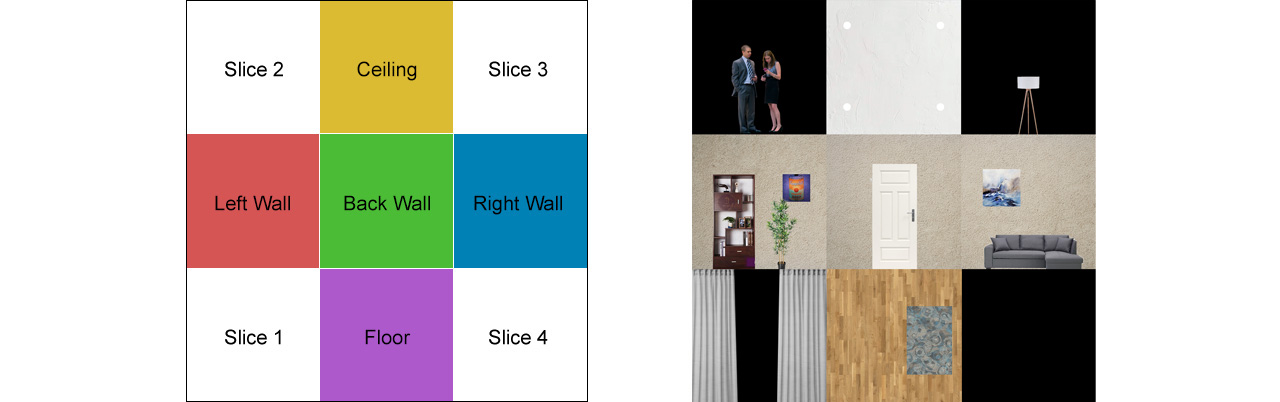
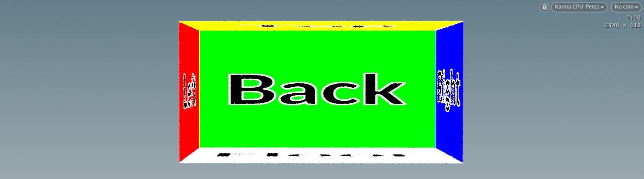
The fundamental setup uses one map that’s projected onto a plane. Both, shader setup and map, have to meet certain requirements to work properly. Interior maps are EXR files with an alpha channel and a fixed pattern to ensure that each room element appears on the correct wall. The left image below shows the order of walls and slices. The right image is an actual interior map. An alpha map lets the slices appear transparent.
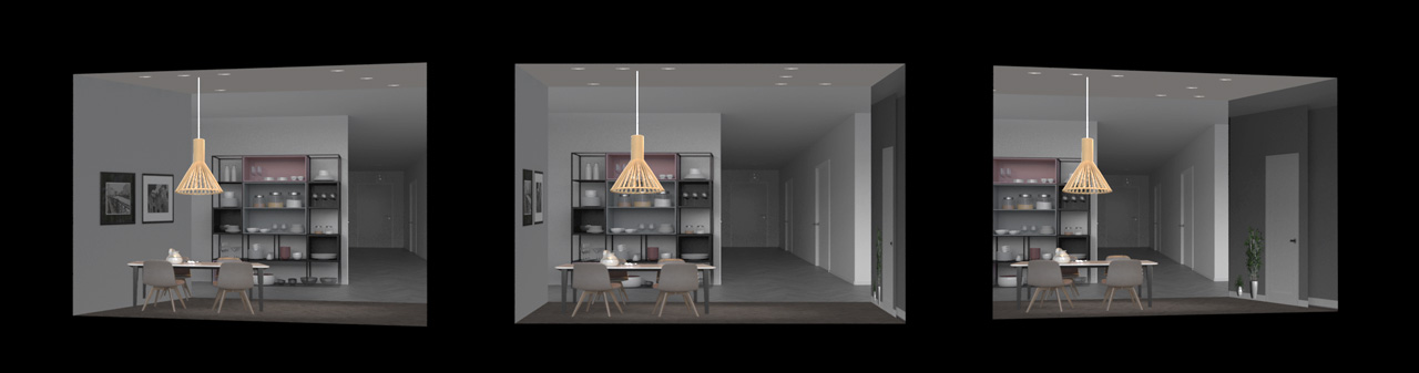
Here are some rendered views.
Geometry requirements 
The Karma Room Map Shader performs various calculations on the used geometry to determine the map’s dimensions and orientation. With native Houdini geometry, this process is straightforward, but sometimes objects from external sources don’t fulfill the shader’s requirements. A common issue with geometry from other DCCs is an inconsistent vertex order and differently orientated vectors.
Follow this link to get more information on troubleshooting faulty geometry.
SOP setup 
You can create the SOP nodes in the obj network, but also through a ![]() SOP Create LOP in the stage network. In this and the following examples, all geometry nodes are located on the obj network.
SOP Create LOP in the stage network. In this and the following examples, all geometry nodes are located on the obj network.
-
Press ⇥ Tab to open the Tab menu and create a
 Geometry OBJ. Double-click the node to dive into it.
 -
Add a
 Grid SOP. This node represents the window.
 -
Change the grid’s Orientation to XY Plane.
-
For Size, enter
2, 1. -
Set Rows and Columns to
2each to simplify the projection geometry. -
Add a
 Room Map Frame SOP and connect its input with the output of the grid node. The Karma Room Map shader requires some information to scale and orient the map correctly. This node creates the appropriate attributes.
 -
Turn on Visualize to see the most important attributes.
-
To terminate the short network, add a
 Null SOP and connect it to the Room Map Frame SOP’s output. Rename the null, e.g. to
 GEO_WINDOW, and turn on the blue Display/Render flag.
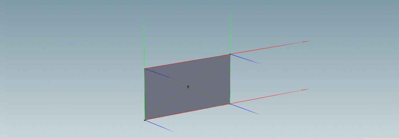
Above you can see the three axes for each vertex, representing the red tangentu (Utan) and green tangentv (Vtan) vectors. The blue vector is the cross product from tangentu and tangentv and represents the grid’s normal. The blue vector’s direction indicates, for example, on which side of the grid the map appears. You can use the node’s various checkboxes to change the map’s orientation without changing the object’s geometry. Use Up Vector, however, fixes many issues with an inconsistent vertex order.
Stage setup 
The following, very basic LOP setup imports the SOP network to the USD stage to create a preview.
-
On the stage level, press ⇥ Tab and create a
 SOP Import LOP.
 -
SOP Path must point to the
GEO_WINDOWnull on the obj network. If you have followed the steps above, the path is/obj/geo/GEO_WINDOW. Alternatively, click the node chooser icon and navigate to
 GEO_WINDOW. -
Add a
 Material Library LOP and connect its input with the output of the SOP Import LOP.
For final rendering you also need a ![]() Camera LOP, the
Camera LOP, the ![]() Karma Render Settings LOP and an
Karma Render Settings LOP and an ![]() USD Render ROP node.
USD Render ROP node.
The Karma Room Map shader 
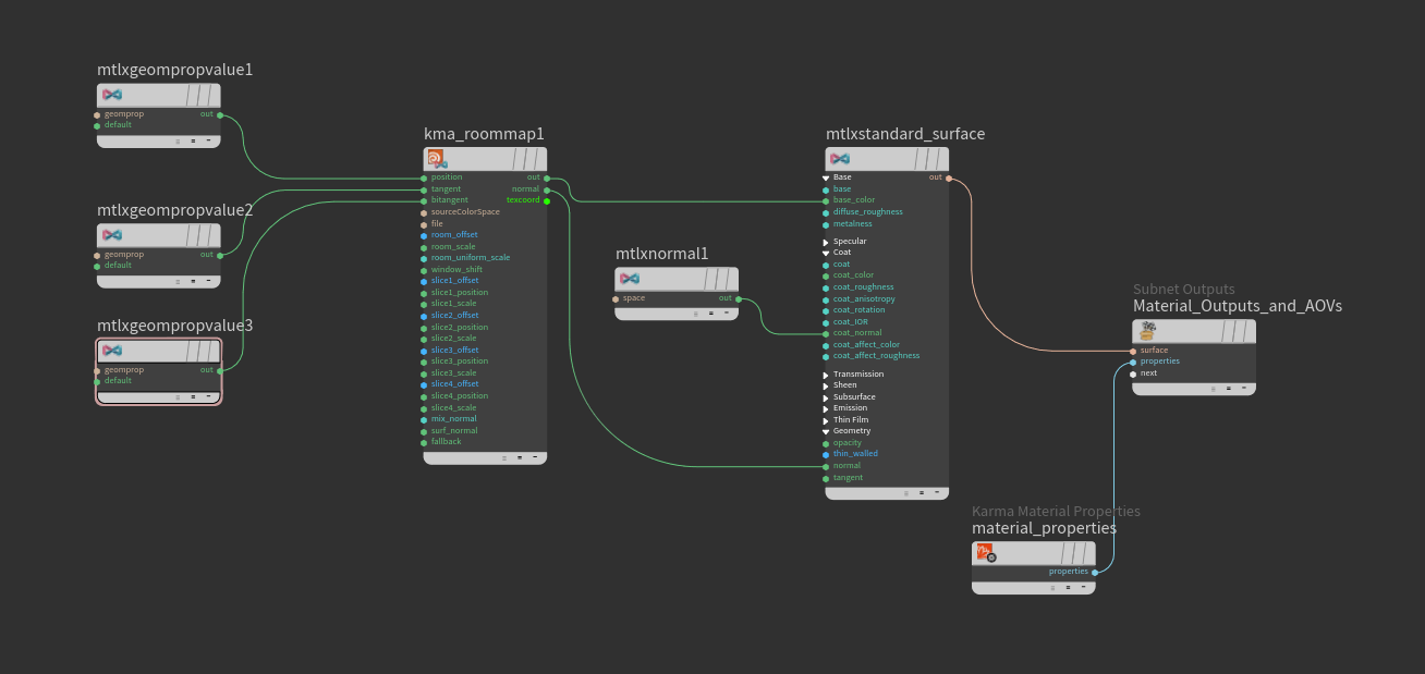
In Houdini 20, materials are created inside specific ![]() Subnet VOPs. Once you've created a subnet and dived into it, the Tab menu provides only shader nodes that work with the chosen subnet. Here’s the entire shader network (the steps for its creation are explained below).
Subnet VOPs. Once you've created a subnet and dived into it, the Tab menu provides only shader nodes that work with the chosen subnet. Here’s the entire shader network (the steps for its creation are explained below).
-
Double-click the Material Library LOP to dive inside.
-
From the Tab menu, choose
Karma Material Builder. Double-click this node as well and dive inside. The subnet comes preconfigured with several nodes. You can delete themtlxdisplacementnode. -
Add a Karma Room Map LOP and connect it’s
outoutput to thenextinput of theMaterial_Outputs_and_AOVsnode. -
The File parameter lets you choose a map. By default, there’s a
karma/roommap_debug.exrentry. For now, keep this map.The node’s first three inputs expect geometry attributes from the Room Map Frame SOP. The SOP node analyses the window’s scale, position and orientation for the correct projection of the interior map.
-
To bind the window’s attributes to the shader, add three
 MtlX Geometry Property Value VOPs. Connect their
 outpins to the shader’sposition,tangent, andbitangentinputs. -
For all three MtlX Geometry Property Value VOPs set Signature to Vector 3.
-
The three Geomprop parameters are
roomP,tangentuandtangentv.
The MtlX Standard Surface 
You can now connect the Karma Room Map shader to a ![]() MtlX Standard Surface VOP. The material creates a realistic impression, where reflections, color, and brightness match the lighting situation.
MtlX Standard Surface VOP. The material creates a realistic impression, where reflections, color, and brightness match the lighting situation.
-
Connect the room map shader’s
outoutput with thebase_colorinput of the material. -
Connect the shader’s
normaloutput with the material’snormalinput. -
To create a glass effect for the window, add a
MtlX Normal VOP and connect it to the material’s coat_normalinput. -
The Karma Room Map VOP’s Mix Normals parameter adds fake normals to each room wall to mimic the interior’s diffuse appearance. This way you can adapt the room’s look to the ambient light situation.
If you have created a Karma Material Builder subnet from the Tab menu, then the MtlX Standard Material node is already connected to Material_Outputs_and_AOVs node and you're ready to apply the material to the window object(s).
Tip
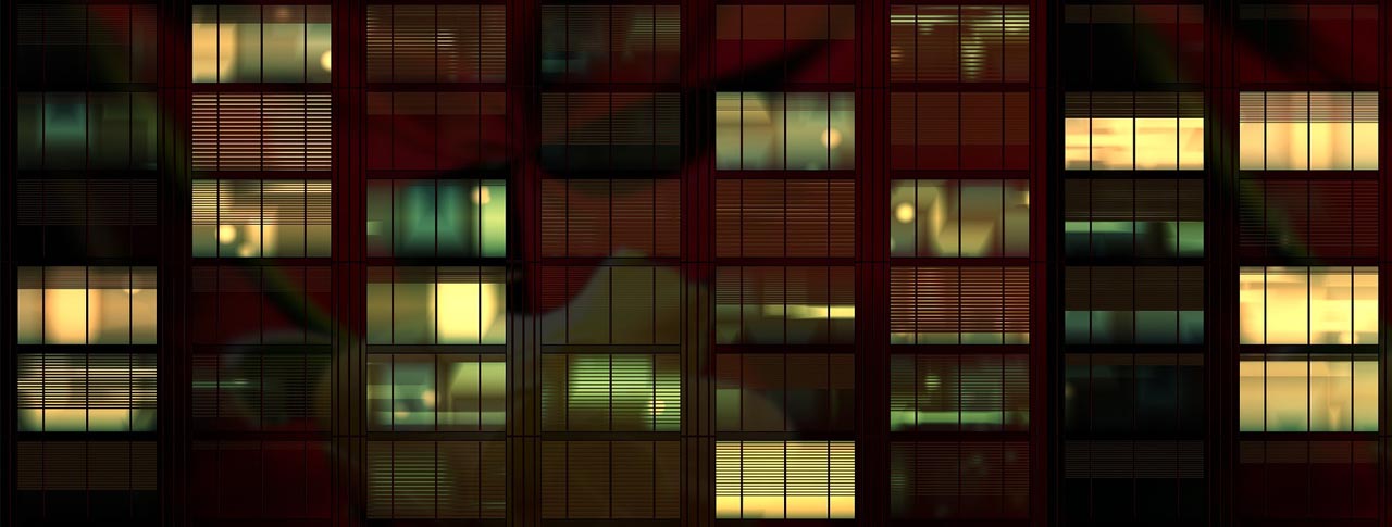
If you want to create a night scene with illuminated interior maps, increase the material’s Emission parameter. Note that you need appropriate maps for night shots. Commercial packages often provide day and night maps.
Previewing the result 
You can now return to the stage level and preview the result. In the viewport, set the render delegate to Karma CPU or Karma XPU. After a few moments you should see something similar to the image below.
Now you can start to customize the room. The shader VOP provides parameters to scale the map, change the room’s depth and turn on slices.
-
You can use the Scale parameters to control the virtual room’s dimensions. With a Z value of
2, for example, the room appears deeper. -
When you turn on the Slice parameters, you can see four differently colored cards inside the room. Use Slice Position and Slice Scale to define the slices' appearance.
-
Load your own File to change the interior.
Multi-window panes 
The Single-window setup shows how to work with one window, but windows can also consist of multiple elements. The Karma Room Box shader is capable of projecting interiors on complex and even non-planar arrangements. A roomID primitive attribute tells the shader, which elements belong to the same window. The shader looks for this attribute and doesn’t require an extra MtlX Geometry Property Value VOP to connect it.
Note
This scene is based on the Single-window setup. Please follow the steps from this guide above before you proceed.
SOP setup 
In this example, you copy the original grid to create a total of three panes.
-
On the obj level, dive into the
geo1node and selectgrid1. -
Change Scale to
1, 2to get an upright rectangle. -
From the Tab menu, add two
 Transform SOPs. Connect the output of
 grid1with the input oftransform1andtransform2. You now have two branches and each branch/transform node contains a copy of the original grid. -
On the first transform, set Translate to
-1, 0, -0.25and Rotate to0, -30, 0. -
On the second transform, set Translate to
1, 0, -0.25and Rotate to0, 30, 0. -
Add a
 Merge SOP, then connect the grid and transform nodes its input.
 -
Connect the Merge SOP’s output to the input of
roommapframe1. Below you can see what you should get.

The roomID attribute 
When you switch to Solaris and do a preview render, you will see that every pane has its own texture, but the map should span over the entire glass front instead.
-
Add an
 Attribute Wrangle SOP and place it between
 merge1androommapframe1to connect its first input. -
On the VEXpression field enter
i@roomID = 100;to create an attribute that assigns the same ID to all panes. -
From the Run Over dropdown menu, choose Primitives to apply the
roomIDattribute to the glass panes. -
Select
roommapframe1. Change Window Mode to Attribute to unlock Primitive Attribute. The default entry isroomIDand this corresponds with the wrangle’s attribute. You can also see that the orientation of the blue and red vectors has changed. -
To make sure that the interior map is visible on the glass front’s convex side, turn on Invert U.
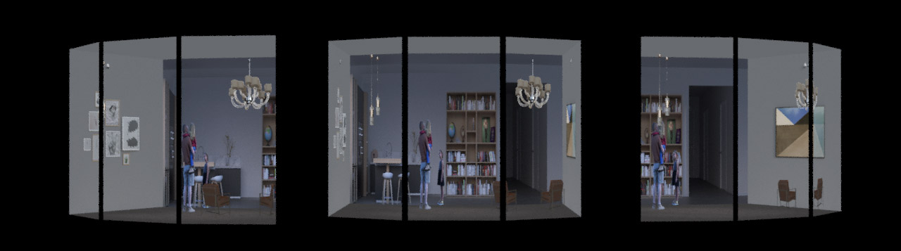
The LOP part doesn’t require any changes and you can start rendering a preview. You should now see something similar to the image below. The image shows three different viewing angles.
Multiple floors 
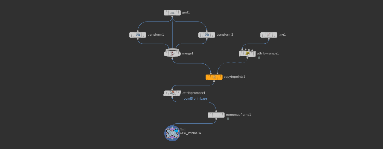
The glass front in the previous example can be copied to create several floors similar to an office building and each floor should show a different interior. Start with the window geometry. Here is the network you will be creating.
-
Dive into the
geo1node on the obj level. -
Add a
 Line SOP to determine the number of floors. In this example, Length is
 6.25and Points is4. -
Delete the existing Attribute Wrangle and create a new one. Connect its first input with the output of the Line SOP.
-
The VEXpression is
i@roomID = @ptnum + 200. The new@ptnumattribute adds the line’s point numbers. Currently, theroomIDis copied to the windows' points. This is going to be changed in a later step. -
Add a
 Copy to Points SOP. Connect its first input with the output of
 merge1. Link the second input to the output ofcopytopoints1. -
An
 Attribute Promote SOP copies the
 roomIDattribute to the windows. Connect its input with the output ofcopytopoints1. -
For Original Name, enter
roomID. -
Set New Class to Primitive.
-
Connect the output of
roommapframe1with the input ofattribpromote1.
When you turn on the Null SOP’s blue Display/Render flag, you should see four floors. Each floor has three windows. You should also see the roomID numbers. If not, select roommapframe1 and turn on Visualize.

Randomizing maps 
The Karma Room Map shader has {Slice} Offset UDIM parameters to switch to another texture in a file sequence. A file sequence consists of several maps with equal names and extensions, but varying UDIM indices, for example
-
interior.1001.exr,interior.1002.exr,interior.1003.exr,interior.1004.exr
To make the render engine aware of the file sequence, replace the indices through a token
-
interior.<UDIM>.exr
Use this common notation as a file name for the shader’s File parameter (note that you also need a path, pointing to the files). When you use the Offset UDIM slider to change the maps, you will also see that all floors have the same map applied. If you want a different map for each floor, you have to randomize the maps.
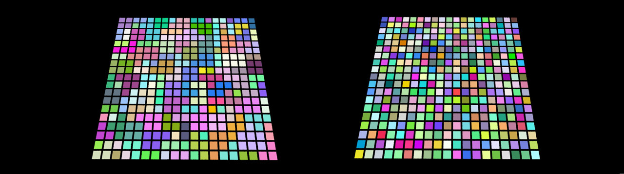
One solution is to drive Voronoi noise through the roomP attribute that stores a window’s position. By default, there’s a high probability that you get the same map applied several times, especially in setups with just a few windows. To fix that you can introduce a factor to control the Voronoi noise, while higher values add more randomness. The comparison below shows this concept. Without a factor, nearby Voronoi cells often have equal colors, indicating a high probability for identical maps. In the right image, a factor of 100 results in more variation.
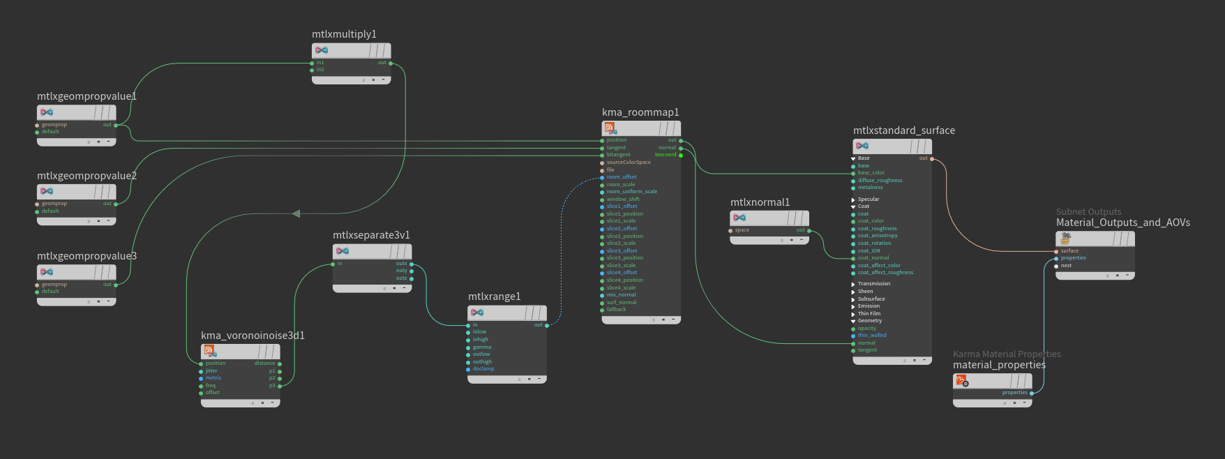
Here’s how to use the noise for randomizing maps.
-
Dive into
stage/materiallibrary1/karmamaterial -
Add a
MtlX Multiply VOP and connect in1withoutof the MtlX Geometry Property Value node with theroomPattribute. -
For Input 2 enter
50, 50, 50. With just four windows this is a good starting value for randomizing the interior maps. -
Lay down a
 Karma Voronoi Nose 3D VOP. Link
 positionwith with themtlxmultiply1node’sout.The Voronoi cell position vectors are available at the
poutputs. The vectors must be split into their components again to drive the shader’s UDIM parameter. -
Add a
MtlX Separate Vector 3 VOP to get the components. Connect the node’s ininput withp3from the Voronoi noise (p3normally gives more randomness). -
Add a
MtlX Range VOP. This node remaps the incoming values. Connect its ininput with the MtlX Separate VOP’souty. On the separate VOP you can see an Outhigh parameter. The value must correspond with the number of available maps. In this example there are four maps for four windows, so the parameter’s value is4. -
Connect the
outpin with the shader’sroom_offsetinput.
Your network should look as shown below.
Randomizing slices 
Slices add extra layers to the interior to create a deeper spatial impression. When you open the shader’s parameter and turn on Slice {n}, you can see Slice Offset UDIM parameters. If an interior map has slices, you can use the slider to swap the slices. An interior map can have up to four slices.
You can use the method from Randomizing maps to drive the Slice Offset UDIM parameters.
-
All you have to do is adding more MtlX Range VOPs and connect them with the
out[xyz]outputs of the MtlX Separate 3 node. -
Then you set the range VOPs' Outhigh parameters to
4- the maximum number of slices per map. Empty slices have a black background and considered to be completely transparent. -
Connect the range VOPs'
outpins to theslice{n}_offsetinputs of the shader.
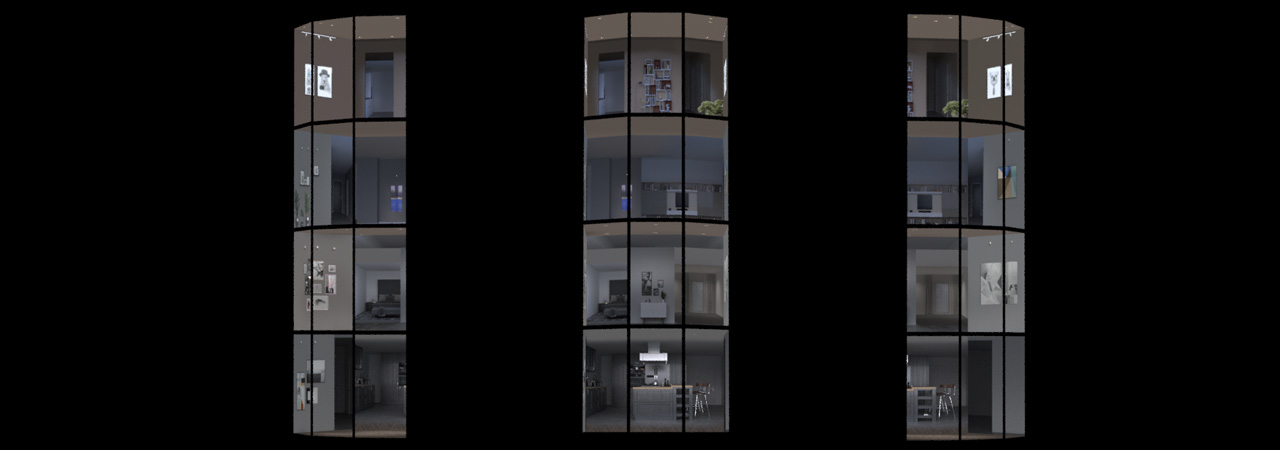
Below you can see three different views of the randomized interior maps on multiple windows and floors.
Curved multi-window panes 
The Karma Room Map shader also supports complex curved windows. This allows for the creation of modern buildings and glass fronts with organic shapes. The following example crates a curved window from a polygon curve.
SOP setup 
The window’s geometry is created from two polygon curves. The space between the curves is filled with polygons to get a solid object. Note that the guide below is a basic method to illustrate the concept.
-
On the obj level, open the Tab menu and create a
Geometry OBJ node. Double-click the node to dive into it. -
Inside the Geometry node, add a
 Curve SOP. Move the mouse over the viewport and press 2 to activate the Top perspective. Then, press Enter to get into drawing mode.
 -
Make sure that the node’s Primitive Type is set to Polygon.
-
Use the
 to draw points. More points create a smoother surface. Press Enter again to terminate the curve.
 -
Add a Line SOP and set Length to
2(or any other value). -
A Copy to Points SOP copies the curve to the line’s points.
-
Connect the Copy to Points SOP’s first input to the curve node’s output; the second input is linked to the line’s output.
-
Add a
 Skin SOP to create polygons between the curves. Connect the first input with the copy node’s output.
 -
A
 Fuse SOP cleans up the geometry by snapping points together.
You now have a solid object for the map’s projection. The remaining steps are the same as in the previous examples.

-
The Karma Room Map Frame SOP adds all relevant attributes. Add the node and connect its input with output of the network’s last node. The creation of a custom
roomIDattribute isn’t necessary here, and all polygons should have a commonroomIDvalue of0. -
Terminate the chain with a Null SOP and rename it to
GEO_WINDOW, for example.
Stage setup 
The LOP setup for rendering with Karma follows the previous descriptions: the Karma Room Map shader requires the attributes from the Karma Room Map Frame SOP and an interior map. If you have multiple copies of the curved window, you can again use the Randomizing maps and Randomizing slices methods to apply different maps. Here are two different views of a curved window.
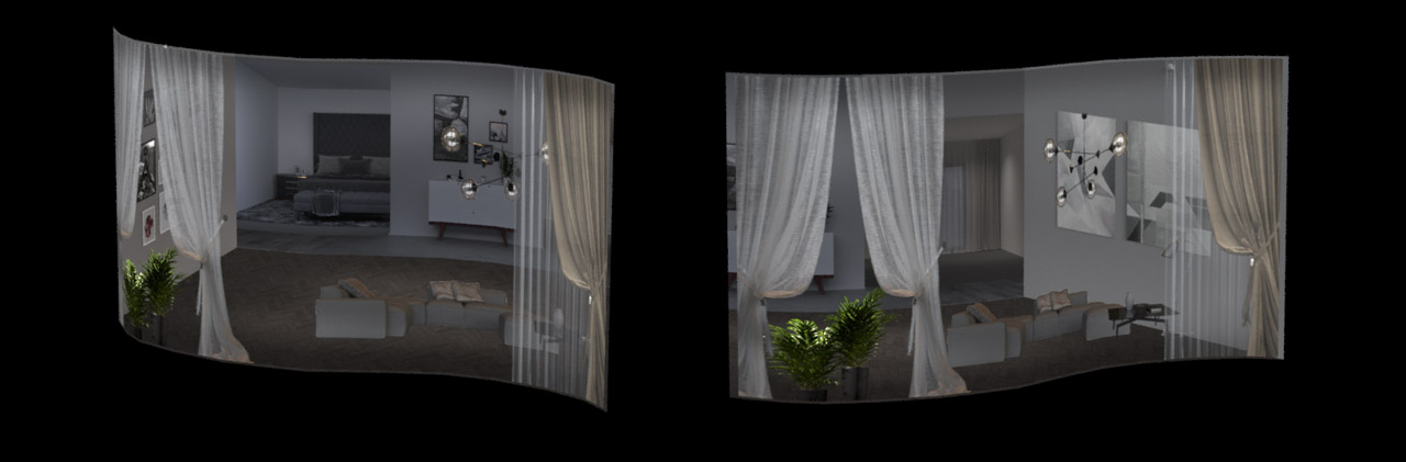
Once you have understood the concept, you will see that this shader is very robust and flexible. The shader also works with different shapes and lets you control all relevant attributes. You only need a single shader node to furnish a complete building.
The primbasis attribute 
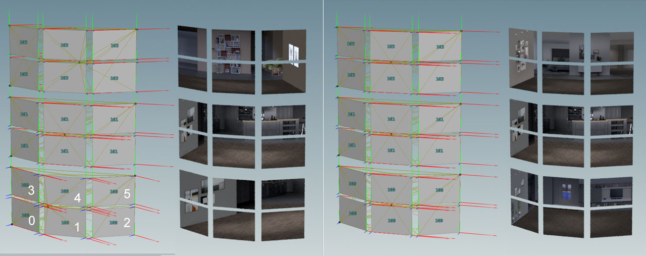
This is a more advanced technique for adjusting and aligning orientation. The left image above shows a setup with three floors. You can see that the blue normal and green tangentv vectors are different for every window group. The primbasis attribute lets you align the vectors by using a reference window element.
-
The
roomIDattribute’s values are 100, 101 and 102. -
Each window contains six individual elements, internally numbered from 0 to 5.
-
Based on the
roomIDvalues, the Karma Room Map Frame SOP creates primitive groups to calculate the relevant vectors.
In this example, the window elements <0,3>, <1,4> and <2,5> have the same orientation. When you set primbasis to 0, as in the right image, all vectors are aligned to the left bottom window element. With primbasis = 2, the reference vectors are taken from the right bottom element.
Troubleshooting 
The Karma Room Frame SOP creates several attributes from a window’s geometry. The attributes are essential for a correct projection of the interior map. A typical sources of error are incorrect vertex order or corrupted geometry from external DCCs. You can already fix many problems with the Room Map Frame SOP’s options. Try to
-
Use Up Vector when the geometry’s vertex order is not consistent
-
invert and swap tangent vectors in case of flipped or rotated maps, but also when the map is projected on the “wrong” side of the window
-
use the
 Reverse SOP to reverse or cycle the vertex order for all faces
 -
keep your window geometry as clean and simple as possible
-
clean up geometry with a
Fuse SOP.