| Since | 18.0 |
The Karma Render Settings LOP creates ![]() render vars, a
render vars, a ![]() render product and a
render product and a ![]() render settings primitive, configured for Karma.
render settings primitive, configured for Karma.
Parameters 
Render Settings Primitive Path
This node creates a RenderSettings prim with the configuration you set up using the parameters. This is the scene tree path where this node will create the RenderSettings prim.
Output Picture
An output image filename (usually an .EXR file), or ip which renders the image in MPlay.
Include $F in the file name to insert the frame number. This is necessary when rendering animation. See expressions in file names for more information.
Camera
Path to a USD camera (UsdGeomCamera) prim to render the scene from.
Resolution Mode
Use the USD Camera’s aperture aspect ratio to automatically set one dimension of the resolution.
The computed parm is set using an expression, but is locked to prevent accidental edits.
Manual
Set the resolution height and width values.
Set Width, Compute Height from Aperture
Set the width size, while height is computed from the width and the camera aspect ratio.
Set Height, Compute Width from Aperture
Set the height size, while width is computed from the width and the camera aspect ratio.
Resolution
The horizontal and vertical size of the output image, in pixels.
Rendering Engine
Select the rendering engine.
CPU
Runs entirely on the CPU. Since this engine is entirely in software, it will generally have more features and more correct output, however it is much slower than the XPU engine.
XPU
The XPU engine uses available CPU and GPU (graphics card hardware) resources. Since this engine inherits the limits of what can be done on a GPU, it will generally lag behind the CPU engine in features, however it is much faster than the CPU engine.
Simplified Shading
Disable all shading and lighting (render with one headlight on the camera). This might be useful for preview purposes if a shaded view is too slow to render.
Primary Samples
The number of ray-samples sent through each pixel. More samples will result in a less noisy image. Pixel Samples and Primary Samples are the same.
Path Traced Samples
The number of ray-samples sent through each pixel when using the path traced convergence mode. More samples will result in a less noisy image.
Rendering 
Sampling 
Min Secondary Samples
Minimum number of rays to cast in per-component variance anti-aliasing.
Max Secondary Samples
Maximum number of rays to cast in per-component variance anti-aliasing.
Diffuse Quality
This parameter acts as a multiplier on Min Secondary Samples and Max Secondary Samples for indirect diffuse component.
Reflection Quality
This parameter acts as a multiplier on Min Secondary Samples and Max Secondary Samples for indirect reflect component.
Refraction Quality
This parameter acts as a multiplier on Min Secondary Samples and Max Secondary Samples for indirect refract component.
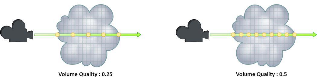
Volume Quality
This parameter acts as a multiplier on Min Secondary Samples and Max Secondary Samples for indirect volume component.
SSS Quality
This parameter acts as a multiplier on Min Secondary Samples and Max Secondary Samples for the SSS component.
Light Sampling Mode
Whether Karma should perform uniform sampling of lights or whether rendering should use the light tree. The light tree can be significantly faster for scenes that have large numbers of lights.
Some lights cannot be added to the light tree, and will all be sampled by Karma:
-
Dome Lights
-
Distant Lights
-
Point Lights
-
Lights with Light Filters
-
Lights with shaping controls (i.e. spot lights)
Light Sampling Quality
This is a global control to improve sampling quality for all lights. This acts as a multiplier on the individual light quality controls. Increasing the quality will improve direct light sampling as well as shadows/occlusion.
Screendoor Samples
The number of transparent samples to be shaded as a ray travels through partially opaque objects. Increasing this value will result in less noise in partially opaque objects and is generally less costly than increasing Pixel samples, Volume Step Rate, or Min and Max ray samples. This parameter will not have any effect on noise from Indirect Sources however.
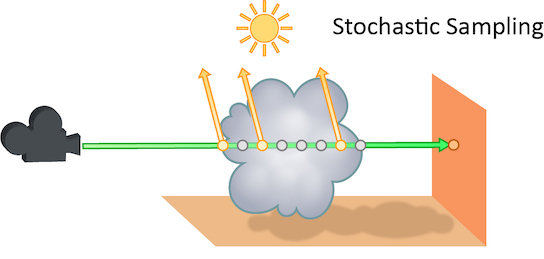
Volume Step Rate
How finely or coarsely a volume is sampled as a ray travels through it. Volumetric objects are made up of 3-dimensional structures called Voxels, the value of this parameter represents the number of voxels a ray will travel through before performing another sample.
The default value is 0.25, which means that every one of every four voxels will be sampled. A value of 1 means that all voxels are sampled and a value of 2 means that all voxels are sampled twice. Thi means that the volume step rate value behaves in a similar way to pixel samples, acting as a multiplier on the total number of samples for volumetric objects.
Keep in mind that increasing the volume step rate can dramatically increase render times, so it should only be adjusted when necessary. Also, while increasing the default from 0.25 can reduce volumetric noise, increasing the value beyond 1 will rarely see similar results.
Limits 
Diffuse Limit
The number of times diffuse rays can propagate through your scene.
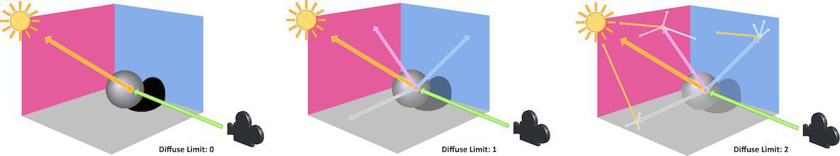
Unlike Reflect Limit and Refract Limit, this parameter will increase the overall amount of light in your scene and contribute to the majority of global illumination. With this parameter set to values greater than 0, diffuse surfaces will accumulate light from other objects in addition to direct light sources.
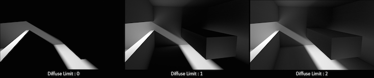
In this example, increasing the Diffuse Limit has a dramatic effect on the appearance of the final image. To replicate realistic lighting conditions, it is often necessary to increase the Diffuse Limit. However, since the amount of light contribution usually decreases with each diffuse bounce, increasing the Diffuse Limit beyond 4 hardly improves the visual fidelity of a scene. Additionally, increasing the Diffuse Limit can dramatically increase noise levels and render times.
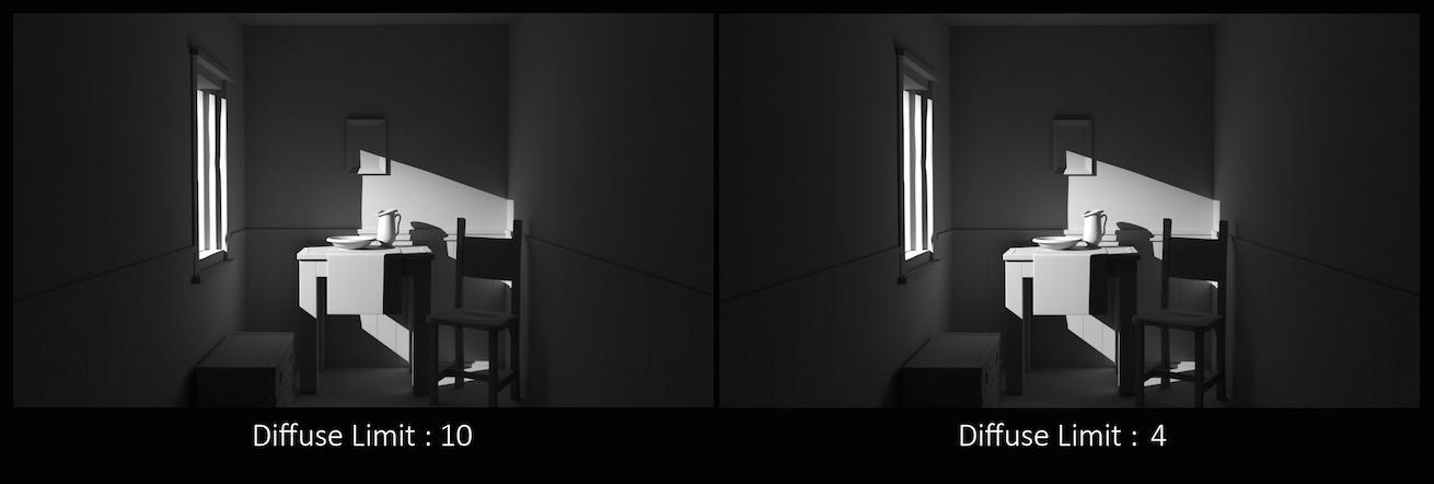
This is a float because all limits are stochastically picked per-sample, so for example you can set the diffuse limit to 3.25 and have 25% of the rays with a diffuse limit of 4 and 75% of rays with a diffuse limit of 3.
Reflection Limit
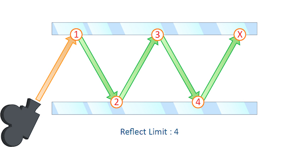
The number of times a ray can be reflected in your scene.
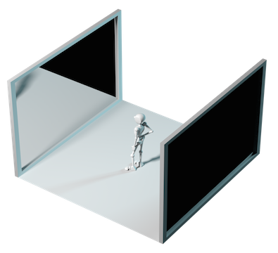
This example shows a classic “Hall of Mirrors” scenario with the subject placed between two mirrors.
This effectively creates an infinite series of reflections.
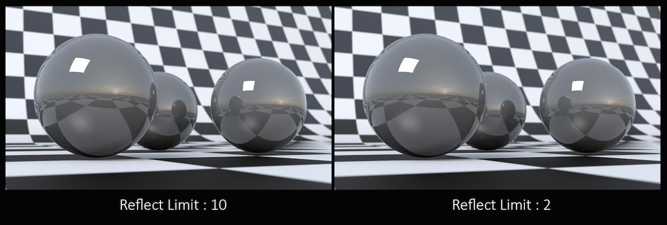
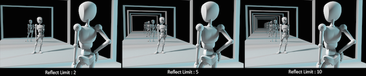
From this camera angle the reflection limits are very obvious and have a large impact on the accuracy of the final image. However, in most cases the reflection limit will be more subtle, allowing you to reduce the number of reflections in your scene and optimize the time it takes to render them.
Remember that the first time a light source is reflected in an object, it is considered a direct reflection. Therefore, even with Reflect Limit set to 0, you will still see specular reflections of light sources.
This is a float because all limits are stochastically picked per-sample, so for example you can set the diffuse limit to 3.25 and have 25% of the rays with a diffuse limit of 4 and 75% of rays with a diffuse limit of 3.
Refraction Limit
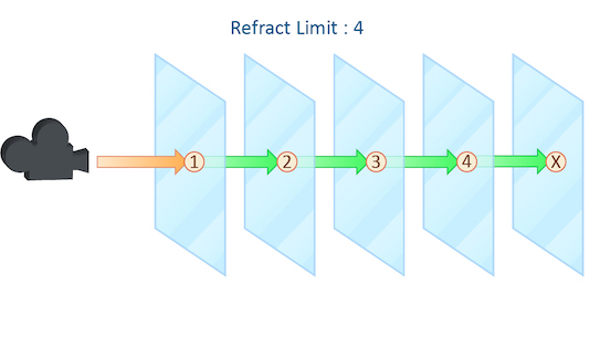
This parameter control the number of times a ray be refracted in your scene.
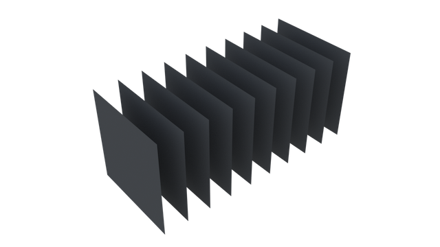
This example shows a simple scene with ten grids all in a row.
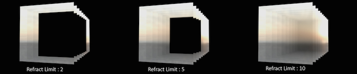
By applying a refractive shader, we will be able see through the grids to an image of a sunset in the background.
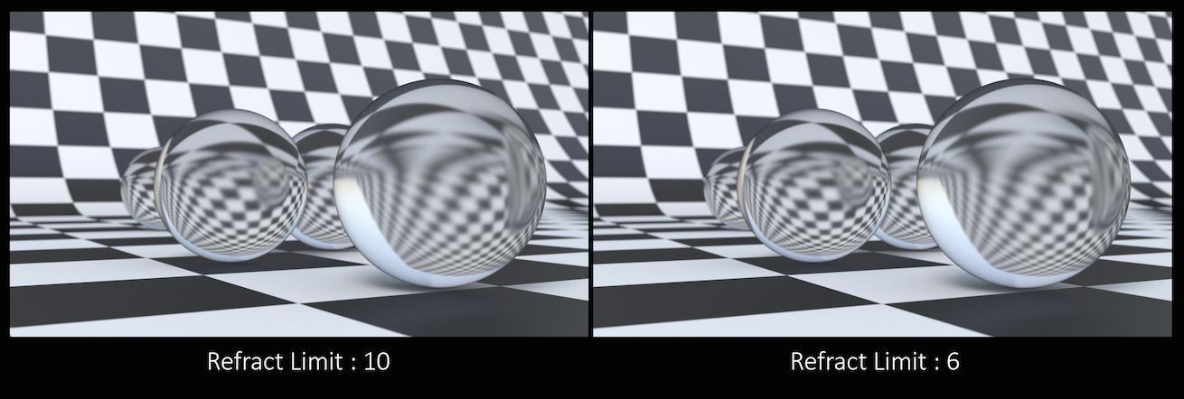
From this camera angle, in order for the image to be accurate, the refraction limit must match the number of grids that that are in the scene. However, most scenes will not have this number of refractive objects all in a row and so it is possible to reduce the refract limit without affecting the final image while also reducing the time it takes to render them.
Keep in mind that this Refract Limit refers to the number of surfaces that the ray must travel through, not the number of objects.
Remember that the first time a light source is refracted through a surface, it is considered a direct refraction. Therefore, even with Refract Limit set to 0, you will see refraction of light sources. However, since most objects in your scene will have at least two surfaces between it and the light source, direct refraction is often not evident in your final render.
This is a float because all limits are stochastically picked per-sample, so for example you can set the diffuse limit to 3.25 and have 25% of the rays with a diffuse limit of 4 and 75% of rays with a diffuse limit of 3.
Volume Limit
The number of times a volumetric ray can propagate through a scene. It functions in a similar fashion to the Diffuse Limit parameter.
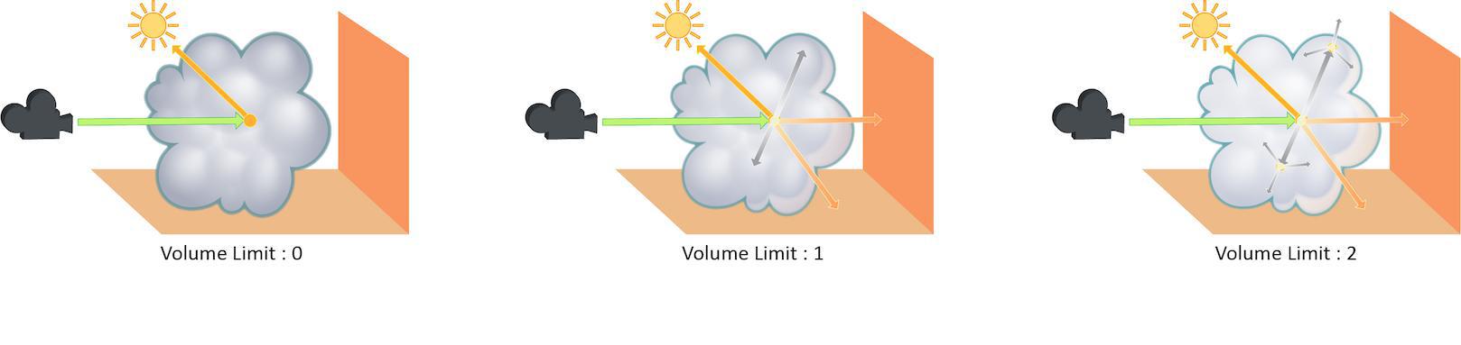
Increasing the Volume Limit parameter will result in much more realistic volumetric effects. This is especially noticeable in situations where only part of a volume is receiving direct lighting. Also, in order for a volumetric object to receive indirect light from other objects, the Volume Limit parameter must be set above 0.
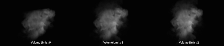
With the Volume Limit set to values greater than 0, the fog volume takes on the characteristic light scattering you would expect from light traveling through a volume. However, as with the Diffuse Limit, the light contribution generally decreases with each bounced ray and therefore using values above 4 does not necessarily result in a noticeably more realistic image.
Also, increasing the value of this parameter can dramatically increase the amount of time spent rendering volumetric images.
This is a float because all limits are stochastically picked per-sample, so for example you can set the diffuse limit to 3.25 and have 25% of the rays with a diffuse limit of 4 and 75% of rays with a diffuse limit of 3.
SSS Limit
The number of times a SSS ray can propagate through a scene. It functions in a similar fashion to the Diffuse Limit parameter.
This is a float because all limits are stochastically picked per-sample, so for example you can set the diffuse limit to 3.25 and have 25% of the rays with a diffuse limit of 4 and 75% of rays with a diffuse limit of 3.
Color Limit
The maximum value a shading sample is allowed to contribute to an LPE image plane to reduce appearance of “fireflies” caused by undersampling of extremely bright light sources. Note that reducing this value can result in an overall reduction in the amount of light in your scene.
Shared Color Limit
When turned on, indirect bounces use Color Limit value and Indirect Color Limit parameter is ignored.
Indirect Color Limit
Color limit applied to indirect bounce only. Note that this parameter is ignored unless Shared Color Limit is turned off.
Russian Roulette Cutoff Depth
Depth at which indirect rays start to get stochastically pruned based on ray throughput.
Camera Effects 
Enable Depth of Field
Turn on the depth of field rendering.
Enable Motion Blur
Whether to turn on motion blur. Changing this in the display options will require a restart of the render.
Per-object Motion Blur
Whether motion blur should be on or off for objects that don’t explicitly have an opinion. If this is On by default, the parameters below let you set the defaults.
Transform Time Samples
The number of samples to compute when rendering transformation motion blur over the shutter open time. The default is 2 samples (at the start and end of the shutter time), giving one blurred segment.
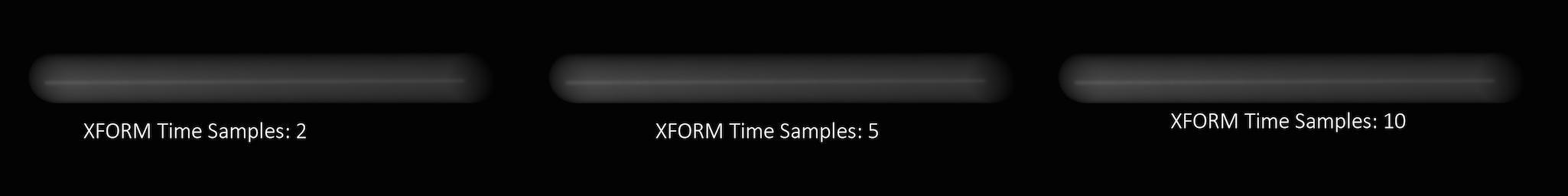
If you have object moving and changing direction extremely quickly, you might want to increase the number of samples to capture the sub-frame direction changes.
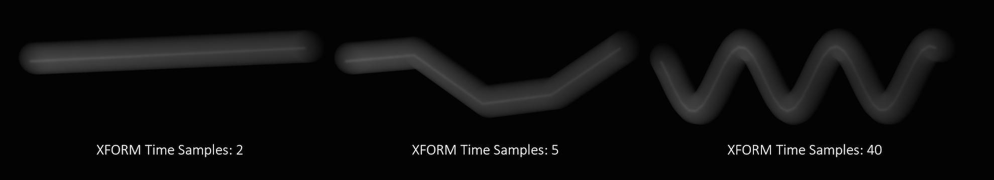
In the above example, it requires 40 transformation samples to correctly render the complex motion that occurs within one frame. (This amount of change within a single frame is very unusual and only used as a demonstration.)
Transformation blur simulates blur by interpolating each object’s transformation between frames, so it’s cheap to compute but does not capture surface deformation. To enable blurring deforming geometry, increase karma:object:geosamples.
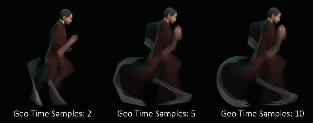
Geometry Time Samples
The number of sub-frame samples to compute when rendering deformation motion blur over the shutter open time. The default is 1 (sample only at the start of the shutter time), giving no deformation blur by default. If you want rapidly deforming geometry to blur properly, you must increase this value to 2 or more. Note that this value is limited by the number of sub-samples available in the USD file being rendered. An exception to this is the USD Skel deformer which allows.
“Deformation” may refer to simple transformations at the Geometry (SOP) level, or actual surface deformation, such as a character or object which changes shape rapidly over the course of a frame.
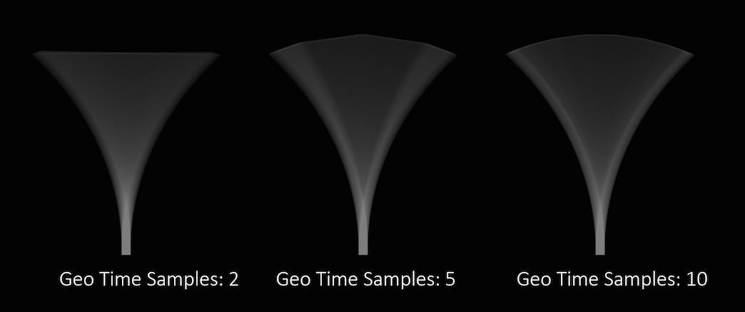
Objects whose deformations are quite complex within a single frame will require a higher number of Geo Time Samples.
Deformation blur also lets you blur attribute change over the shutter time. For example, if point colors are changing rapidly as the object moves, you can blur the Cd attribute.
Increasing the number of Geo Time Samples can have an impact on the amount of memory Karma uses. For each additional Sample, Karma must retain a copy of the geometry in memory while it samples across the shutter time. When optimizing your renders, it is a good idea to find the minimum number of Geo Time Samples necessary to create a smooth motion trail.
Deformation blur is ignored for objects that have Velocity motion blur turned on.
Velocity Blur
This parameter lets you choose what type of geometry velocity blur to do on an object, if any. Separate from transform blur and deformation blur, you can render motion blur based on point movement, using attributes stored on the points that record change over time. You should use this type of blur if the number points in the geometry changes over time (for example, a particle simulation where points are born and die).
If your geometry changes topology frame-to-frame, Karma will not be able to interpolate the geometry to correctly calculate Motion Blur. In these cases, motion blur can use a velocities and/or accelerations attribute which is consistent even while the underlying geometry is changing. The surface of a fluid simulation is a good example of this. In this case, and other types of simulation data, the solvers will automatically create the velocity attribute.
Note
In Solaris, velocities, accelerations, and angularVelocities attributes are equivalent to v, accel, and w in SOPs, respectively.
No Velocity Blur
Do not render motion blur on this object, even if the renderer is set to allow motion blur.
Velocity Blur
To use velocity blur, you must compute and store point velocities in a point attribute velocities. The renderer uses this attribute, if it exists, to render velocity motion blur (assuming the renderer is set to allow motion blur). The velocities attribute may be created automatically by simulation nodes (such as particle DOPs), or you can compute and add it using the ![]() Point velocity SOP.
Point velocity SOP.
The velocities attribute value is measured in Houdini units per second.
Acceleration Blur
To use acceleration blur, you must compute and store point acceleration in a point attribute accelerations. The renderer uses this attribute, if it exists, to render multi-segment acceleration motion blur (assuming the renderer is set to allow motion blur). The accel attribute may be created automatically by simulation nodes, or you can compute and add it using the ![]() Point velocity SOP.
Point velocity SOP.
When Acceleration Blur is on, if the geometry has a angular velocity attribute (w), rapid rotation will also be blurred. This should be a vector attribute, where the components represent rotation speeds in radians per second around X, Y, and Z.
When this is set to “Velocity Blur” or “Acceleration Blur”, deformation blur is not applied to the object. When this is set to “Acceleration Blur”, use the karma:object:geosamples property to set the number of acceleration samples.
velocities) to do linear motion blur.
Instance Velocity Blur
When defining motion blur on instances, the transform of each instance can be blurred in addition to any motion blur occurring on the prototype. This option controls how the instance will compute the motion blur of the transform on each instance. For example, when instancing prototypes to a particle system, you'd likely want to use velocity blur to compute motion blur (the transform on the prototype would be blurred by the velocity on the particles).
No Velocity Blur
Use deformation blur of the instance to compute the blur on the transform.
Velocity Blur
To use velocity blur, the instance must be a point instancer with a velocities attributes on the points, or a native instance with a v primvar.
The velocities attribute (or v primvar) value is measured in Houdini units per second.
Acceleration Blur
To use acceleration blur, the instance must be a point instancer with point velocities and acceleration values. The renderer uses this attribute, if it exists, to render multi-segment acceleration motion blur (assuming the renderer is set to allow motion blur). The accel attribute may be created automatically by simulation nodes, or you can compute and add it using the ![]() Point velocity SOP; this will be converted to
Point velocity SOP; this will be converted to accelerations when the SOP geometry is converted to USD.
Instance Motion Samples
When motion blur on instances is computed using Acceleration Blur or Deformation Blur, this parameter specifies the number of motion segments used for motion blur.
Motion Blur Style
Defines the type of motion blur. The default Rotation Blur is suited for most applications, esp. spinning wheels or rotor blades, but also almost any other type of motion. Linear Blur is only required in very rare cases.
Instance Velocity Blur Scale
Velocity multiplier used to reduce or exaggerate amount of motion blur on volumes.
Disable Image Blur
If you turn this off, Karma still calculates velocities (and the velocities can be stored in an AOV), but it sends all camera rays at shutter open, so the image will not have any apparent motion blur. This may be useful if you simply don’t want any motion blur to create a certain visual effect.
Geometry and Shading 
Render Points as
When rendering point clouds, they can be rendered as camera oriented discs, spheres or discs oriented to the normal attribute.
Render Curves as
When rendering curves, they can be rendered as ribbons oriented to face the camera, rounded tubes or ribbons oriented to the normal attribute attached to the points.
Override Curve Basis
USD supports Curve Basis types that may not be supported directly in Houdini. In some cases, you may want to override the Houdini curve basis. For example, if you have linear curves in Houdini, you may want to render them with a Bezier, B-Spline or Catmull-Rom basis. This menu will force Karma to override the basis that’s tied to the USD primitives.
Note that the topology of the curves must match the target basis. For example, when selecting any cubic curve basis, every curves must have at least 4 vertices. For the Bezier basis, curves must have 4+3*N vertices.
Cull Backfaces
If enabled, geometry that are facing away from the camera are not rendered.
Enable Caustics
Allows evaluation of glossy BSDF that’s seen by indirect diffuse bounce. This is a brute-force solution which may require significant number of diffuse rays to resolve, especially if Caustics Roughness Clamp parameter is set to very small value or Indirect Guiding feature is disabled.
Caustics Roughness Clamp
Increasing this value can make caustics less noisy at the cost of accuracy.
Note
Roughness clamp only works with GGX BSDF and may not have any effect with Phong, cone, or specular BSDFs.
Ray Bias
The minimum distance used when testing if secondary rays from a surface intersect with other objects in the scene. The distance is measure from surface along the direction of the ray. Objects within the ray bias distance are ignored.
Automatic Ray Bias
Automatically compute ideal ray bias. Under Karma CPU, automatic bias applies to everything except procedural mesh and continued rays for partially opaque surfaces and nested dielectrics (the Ray Bias property is still used for those cases). Under Karma XPU, automatic bias applies to everything, but only for polymesh. For all other geometry types (eg points, curves) the Ray Bias property is still used.
Constrain by Maximum Roughness
Roughness parameter in GGX BSDFs are clamped by the maximum roughness value propagated down the ray chain in pathtracing. Enabling this option can cut out a lot of noise in indirect specular (in particular, cases where glossy surface is reflected by a rough specular surface) at the cost of a bit of accuracy.
Automatic Headlight Creation
If there are no lights in the scene, a headlight is created by default. To disable, turn off this checkbox.
Dicing Camera
Specifies a camera that is used for dicing complicated surfaces. This can provide consistent dicing of surfaces when the viewing camera is moving.
Offscreen Quality
This parameter controls the shading quality scale factor for geometry that is not directly visible to the camera. For geometry that is outside the field of view (i.e. visible only to secondary rays), karma will smoothly reduce the shading quality based on the angle between the geometry and the edge of the viewing frustum. Smaller values can increase performance particularly in scenes where the camera is within the displacement bound of nearby geometry, where it permits the hidden primitives to be diced more coarsely than those that are directly visible.
Dicing Quality Scale
This parameter is a global multiplier for dicing quality of all objects.
Image Output 
AOVs (Render Vars) 
In USD, a RenderVar prim (for example, /Render/Products/Vars/diffuse) configures an AOV (arbitrary output variable) to generate during rendering. AOVs are extra “channels” of per-pixel data you can add to the image output (for image formats that support multiple channels per pixel, such as .exr).
By default, this node generates beauty, diffuse, glossy reflection, volume, depth, UV and normal AOVs.
The checkboxes in this section represent commonly used AOVs. You can also create custom AOVs (in the Extra Render Vars section) from Light Path Expressions, material outputs, geometry primvars, and other sources.
Import Render Vars from Second Input
Finds RenderVar prims in this node’s second input and adds them to this stage, so they add to the list of render vars to generate. This allows other LOP nodes (such as Background Plate) to “offer” render vars related to that node to be generated.
Import Render Products from Second Input
Finds RenderProduct prims in this node’s second input and adds them to this stage, so they add to the list of products to generate. This allows other LOP nodes to “offer” products related to that node to be generated.
Pixel Filter
Controls the distribution of pixel samples. Box uses a uniform distribution inside each pixel. Gaussian, Blackman, and Blackman-Harris use smooth, bell-shaped weightings around the pixel center.
Box
A uniform distribution inside each pixel
Gaussian
A Gaussian distribution with a standard deviation of 0.5
Blackman
A Blackman distribution with a radius of 1.5
Blackman-Harris
A Blackman-Harris distribution with a radius of 1.8
Pixel Filter Scale
Scales the default size of the pixel filter. Larger values like 2 blur, smaller values like 0.5 or 0.25 sharpen.
The following checkbox is available next to each common render var:
Split Per LPE Tag
When this is on, the renderer creates additional AOVs specific to each tagged light. To manage LPE Tags for lights, use the ![]() LPE Tag LOP.
LPE Tag LOP.
Component Level Output 
LPE Tag AOV Limit
When splitting AOVs per lights' LPE Tag, specify the maximum number of LPE Tag AOVs beyond which the node will emit a warning.
Omit LPE Tags
When splitting AOVs per lights' LPE Tag, specify a space separated list of lights' LPE Tags which will not create new AOVs.
Output Colorspace
Specify the OCIO color output space for the component.
Beauty
Add the beauty output as a color4f render var named C.
Sample Blending
You can use Solaris filter syntax in this parameter to filter the sample values. The default ["ubox", {}] simply averages all the sample values within each pixel.
Output Colorspace
Specify the OCIO color output space for the component.
Beauty Unshadowed
Add the unoccluded (unshadowed) beauty output as a color3f render var named beautyunshadowed, using the LPE unoccluded;C.*[LO][LO].
Combined Diffuse
Add the combined (any number of bounces) diffuse surface reflection component as a color3f render var named combineddiffuse, using the LPE C<RD>.*L.
Direct Diffuse
Add the direct (no bounces) diffuse surface reflection component as a color3f render var named directdiffuse, using the LPE C<RD>L.
Indirect Diffuse
Add the indirect (one or more bounces) diffuse surface reflection component as a color3f render var named indirectdiffuse, using the LPE C<RD>.+L.
Combined Diffuse Unshadowed
Add the combined (any number of bounces) unoccluded diffuse surface reflection component as a color3f render var named combineddiffuseunshadowed, using the LPE unoccluded;C<RD>.*[LO].
Direct Diffuse Unshadowed
Add the direct (no bounces) unoccluded diffuse surface reflection component as a color3f render var named directdiffuseunshadowed, using the LPE unoccluded;C<RD>L.
Indirect Diffuse Unshadowed
Add the indirect (one or more bounces) unoccluded diffuse surface reflection component as a color3f render var named indirectdiffuseunshadowed, using the LPE unoccluded;C<RD>.+L.
Combined Glossy Reflection
Add the combined (any number of bounces) glossy surface reflection component as a color3f render var named combinedglossyreflection, using the LPE C<RG>.*[LO].
Direct Glossy Reflection
Add the direct (no bounces) glossy surface reflection component as a color3f render var named directglossyreflection, using the LPE C<RG>L.
Indirect Glossy Reflection
Add the indirect (one or more bounces) glossy reflection component as a color3f render var named indirectglossyreflection, using the LPE C<RG>.+L.
Glossy Transmission
Add the glossy transmission component as a color3f render var named glossytransmission, using the LPE C<TG>.*[LO].
BSDF Labelled coat
Add the coat component as a color3f render var named coat, using the LPE C<...'coat'>.*[LO].
Combined Emission
Add the combined (any number of bounces) emission component as a color3f render var named combinedemission, using the LPE C.*O.
Direct Emission
Add the direct (no bounces) emission component as a color3f render var named directemission, using the LPE CO.
Indirect Emission
Add the indirect (one or more bounces) emission component as a color3f render var named indirectemission, using the LPE C.+O.
Visible Lights
Add the visible lights component as a color3f render var named visiblelights, using the LPE CL.
Combined Volume
Add the combined (any number of bounces) volume component as a color3f render var named combinedvolume, using the LPE CV.*L.
Direct Volume
Add the direct (no bounces) volume component as a color3f render var named directvolume, using the LPE CVL.
Indirect Volume
Add the indirect (one or more bounces) volume component as a color3f render var named indirectvolume, using the LPE CV.+L.
BSDF Labelled sss
Add the sss component as a color3f render var named sss, using the LPE C<...'sss'>.*[LO].
Albedo
Add the albedo output as a color3f render var named export_basecolor. Only available with shaders that export this information, such as the principled shader. For MaterialX shaders, the preferred way to create a diffuse albedo AOV is to use the CDA Light Path Expressions.
Ambient Occlusion
Add the ambient occlusion output as a color3f render var named AO.
Ray Level Output 
P (World Space)
Add the world space position as a point3f render var named P.
P (Camera Space)
Add the camera space position as a point3f render var named P.
Depth (Camera Space)
Add the distance from the camera origin as a float render var named depth.
Element (Raw ID)
Add the element ID as a float render var named element.
Prim ID
Add the primitive identifier as a float render var named primid.
UV
Add the primitive hit UV as a float3 render var named UV.
N (Smooth Normal)
Add the primitive hit normal as a normal3f render var named N.
N (Smooth Camera Normal)
Add the camera space primitive hit normal as a normal3f render var named N_camera.
N (Smooth Facing Normal)
Add the viewer-facing primitive hit normal as a normal3f render var named N_facing. Backfaces also face towards the viewer.
N (Facing Ratio)
Add the falloff (dot product) between the viewer and hit normal as a half render var named N_facingratio.
Ng (Geometric Normal)
Add the primitive geometric normal as a normal3f render var named Ng.
Ng (Geometric Camera Normal)
Add the camera space primitive geometric normal as a normal3f render var named Ng_camera.
Ng (Geometric Facing Normal)
Add the viewer facing primitive geometric normal as a normal3f render var named Ng_facing. Backfaces also face towards the viewer.
Ng (Geometric Facing Ratio)
Add the falloff (dot product) between the viewer and geometric normal as a half render var named Ng_facingratio.
Motion Vectors
Add the primitive motion vector as a vector3f render var named motionvector.
Velocity
Add the primitive velocity as a vector3f render var named velocity.
Extra Render Vars 
Render Vars
Use this multiparm to add custom AOVs (render vars) to the image output.
Data Type
The USD data type of the render variable.
When saving to OpenEXR files, the data type is used to determine the channel names. For example, if the data type is color3f, the channel names will be R, G, B, while if the data type is normal3f, the channel names will be x, y, z.
Tip
If you're rendering with husk and want color channel names to be lower case (for example r, g, b), add another ![]() Render Var LOP and use it to set the
Render Var LOP and use it to set the driver:parameters:aov:husk:channel_lower_rgb (bool) render var to true.
Source Name
Where to get the render variable contents. See Source Type below.
The renderer should look for an output with this name as the computed value for the RenderVar.
Tip
In Karma, with Raw and Primvar (including Cryptomatte) Source Type, it’s possible to prefix variable name with noholdouts; to indicate that matte or background holdouts should not contribute to the AOV. For example, to output normal N AOV without holdouts, enter: ray:noholdouts;N
Source Type
How to interpret the Source Name parameter.
Raw
Pass the source name directly to the renderer. This assumes the renderer knows how to interpret the source name string. This is the default.
Primvar
The Source Name is the name of primvar.
Some renderers may use this to ensure that the primvar is provided to the renderer. Other renderers may require that a suitable material network be provided, in which case this is simply an advisory setting.
LPE
The Source Name is a Light Path Expression.
(Some renderers may accept extensions to the OSL Light Path Expression syntax, which will necessarily be non-portable.)
Intrinsic
Currently not implemented. In the future, USD may provide for a portable list of baseline render vars, such as camera depth, that would be implemented by all renderers.
Sample Blending
You can use Solaris filter syntax in this parameter to filter the sample values. The default ["ubox", {}] simply averages all the sample values within each pixel.
Cryptomatte
Enable this to turn this image plane into Cryptomatte layer. See Cryptomatte for more info.
Overlap Limit
Maximum number of IDs that can be stored in a single pixel. A value of 6 is recommended.
Manifest File
Optional external manifest file. It will be saved into same directory as the render product. If this path is unspecified, the manifest will be embedded into render product as metadata.
Output Colorspace
Specify the OCIO color output space for the component.
Filters 
Denoiser
Choose a denoiser to run on the finished image output, or No Denoiser. This utility currently supports Intel Open Image Denoise (included with Houdini) and the NVIDIA OptiX Denoiser (must be installed separately). You must be on a supported platform and have the chosen denoising library installed for this to work.
Tip
You can also run the Intel OIDN exclusively on the CPU using the idnoise tool’s --oidn-cpu option, for example idenoise --oidn-cpu input.exr output.exr. This will prevent OIDN from failing when it’s running out of VRAM.
The NVIDIA OptiX Denoiser only works with NVIDIA cards. It is now included with the NVIDIA driver (version 435 or later).
Karma uses a blue noise distribution. This noise type works better with denoisers, because it has randomization only in high frequencies, while some other noise have randomization in all frequencies. When blue noise is blurred, the high frequency noise is removed and leaves the lower frequencies of the image intact.
Use Albedo
Some denoising libraries can use albedo to get a better sense of the image, guiding how and where it reduces noise.
Use N Input
Some denoising libraries can use normals to get a better sense of the image, guiding how and where it reduces noise.
AOVS
Space-separated list of AOVs to run the denoiser on.
Tone Map
The basic idea behind tone mapping is the conversion from HDR real world luminances to LDR display values, i.e. for making images displayable on monitors. Another aspect is to simulate a particular film look. Film material is designed to have a certain “response” to light to enhance contrast and colors, represented as a characteristic curve. A filmic tone mapping curve is subdivided into toe, shoulder and linear sections for an image’s dark, bright, and mid tones. Houdini provides several common operators for filmic tone mapping and each operator applies a specific S-shaped tone mapping curve.
-
Reinhard, Ward and Aces don’t provide any further parameters to adjust the toe, shoulder and linear sections.
-
Hable, Hable2 and Unreal, however, have specific parameters for customizing the curve.
Tonemap Curve
Tone map curves apply to the Reinhard, Unreal, Aces and Hable operators. The curve is a visual representation of the mathematical model of each operator. You can fine-tune tone mapping through the curve’s control points.
AOVs
Space-separated list of AOVs that will be affected by the chosen Tone Map operator.
Toe
This parameter applies to the Hable, Hable2 and Unreal operators and ranges between 0 and 1. The default values for Hable and Hable2 is 0.5. For Unreal, the default value is 0.55. The value controls the strength (curvature) of the toe segment in dark areas. Higher values create a darker image, smaller values brighten the dark tones.
Shoulder
This parameter applies to the Hable, Hable2 and Unreal operators and ranges between 0and 1. The default values for Hable and Hable2 is 0.5. For Unreal, the default value is 0.26. Shoulder controls to curve’s amount of curvature for bright tone values. The value affects where the shoulder curve starts in the graph: a value of 1 means that the shoulder starts exactly where the toe ends.
Slope
This parameter applies to the Unreal operator and ranges between 0 and 1. The default value is 0.88. Controls the tone mapping curve’s steepness, where higher settings (steeper curve) make the image darker and increase contrast; smaller values brighten the image and make it pale.
Linear
This parameter applies to the Hable operator and ranges between 0 and 2. The default value is 0.3. Tones in the linear section should not (or hardly) change during the tone mapping process and represent the image’s original tones. The Linear value describes the distance between toe and shoulder. Higher values mean that the tow and shoulder sections become smaller, while more tones remain unchanged: the overall curve becomes more linear.
Linear Angle
This parameter applies to the Hable operator and ranges between 0 and 1. The default value is 0.1. Here you control the slope of the linear part of the tone mapping curve.
Toe Length
This parameter applies to the Hable2 operator and ranges between 0 and 1. The default value is 0.5. A small value creates a short toe section that quickly transitions into the linear section. A value of 0 eliminates the toe, and value of 1 means the toe takes up half the curve. Note that there are two ways to disable the toe: you can either set Toe Length or Toe to 0.
Shoulder Length
This parameter applies to the Hable2 operator and ranges between 0 and 1. The default value is 0.5. Shoulder Length describes how many F stops you want to add to the dynamic range of the curve. Here you control the transition point from the linear section to the shoulder section.
Shoulder Angle
This parameter applies to the Hable2 operator and ranges between 0 and 1. The default value is 1. Here you control how much overshoot you want to add the curve’s shoulder.
OCIO
OCIO image filters can be added to various render vars/image planes.
Enable
Enables the OCIO image filter defined below.
Planes
The render var names to which the OCIO image filter will be applied.
Output Space
Specify the OCIO color output space the image filter will apply.
Input Space
In most cases this should be left at data. There may be some strange case where the source of the AOV is already in a defined color space, in which case you can specify the source space here.
Looks
Space-separated list of looks to apply to the finished image. A “look” is a named OCIO color transform, usually intended to achieve an artistic effect. See the OCIO documentation for more information.
Color Limits
A color limit clamps the value a shading sample is allowed to contribute to an LPE image plane, to reduce appearance of “fireflies” caused by undersampling of extremely bright light sources. This multiparm lets you apply separate limits to different sets of render vars.
Enable
Enables the color limit sample filter defined below.
Planes
A space-separated list of AOV names to which this color limit will be applied.
Limit
The maximum value a shading sample is allowed to contribute to these AOVs.
Aspect Ratio 
Aspect Ratio Conform Policy
What to do if the aspect ratio of the output image (Resolution width divided by height) doesn’t match the aspect ratio of the camera aperture (controlled by attributes on the camera). This allows a standard renderer to do something reasonable when you switch between cameras.
Expand Aperture
If necessary, expand the camera aperture to match the image.
Crop Aperture
If necessary, crop the camera aperture to match the image.
Adjust Aperture Width
If necessary, change the camera aperture width to match the image.
Adjust Aperture Height
If necessary, change the camera aperture height to match the image.
Adjust Pixel Aspect Ratio
Change the aspect ratio of the image to match the camera.
Data Window NDC
Directs the renderer to only render within this window of the entire output image. You specify the window as minX, minY, maxX, maxY, where each number is a normalized value from 0 to 1. 0, 0 is the bottom left, 1, 1 is the top right, 0.5, 0.5 is the center, and so on. The default is 0, 0, 1, 1 (no cropping). Note that you can use negative values. For example, -0.1, -0.1, 1.1, 1.1 will give you 10% overscan on each side.
There’s also an associated dropdown menu with several preadjusted percentage values.
You can use this window to temporarily crop the render to a smaller region, for testing purposes.
Pixels are only rendered if they are fully inside the window.
The normalized coordinates map to the image after any adjustments by the Aspect ratio conform policy.
Pixel Aspect Ratio
The aspect ratio (width/height) of image pixels (not the image itself).
The default is 1.0, indicating square pixels.
Meta Data 
Artist
The name of the person, department, or studio that created the image file. The node will set this field on the output image if the image format supports metadata (for example, .exr).
Comment
An arbitrary comment, for example a description of the purpose of the output image. The node will set this field on the output image if the image format supports metadata (for example, .exr).
Hostname
The name of the computer that generated this the output file. The node will set this field on the output image if the image format supports metadata (for example, .exr).
EXR Compression
Sets the compression for saved OpenEXR files. When saving multi-part OpenEXR files, you can specify compression per AOV through a ![]() Render Var LOP.
Render Var LOP.
Deep Output 
Deep Camera Map
Generate a deep camera map image recording depth.
Deep camera maps are rendered images, where semi-transparent areas (such as volumes) between the camera and the nearest opaque surface are stored with depth information. Each pixel in the image is represented as a curve describing how the transparency value changes across the depth of the scene. This allows you to composite rendered images and have the semi-transparent areas blend correctly according to their depth.
DCM Filename
The filename to save the deep camera map image to (this should be an .exr file).
Include $F in the file name to insert the frame number. This is necessary when rendering animation. See expressions in file names for more information.
DCM Render Vars
Space separated list of RenderVar prim paths (not a list of AOV names). These must be the fully qualified path to the RenderVar prim and the render var name. You can use patterns to match multiple prims. The default is /Render/Products/Vars/*, which matches all prims in the branch where Houdini usually creates RenderVar prims. You can also leave this field empty to omit all RenderVars and only include alpha and depth planes (like a Deep Shadow Map).
DCM Compression
Compression value between 0 and 10. Used to limit the number of samples
which are stored in a lossy compression mode for volume samples. The
compression parameter determines the maximum possible error in scalar
channels for each sample. For compression greater than 0, the following
relationship holds: Error = 1/(2^(10-compression))
DCM Of Size
Opacity is usually computed as a full-color value and stored as such. To
cut down on file size, if full color is not needed, this settings can be
used to store a monochromatic version of the full color value.
Set this value to 1 for monochrome, 3 for full color.
DCM Z-Bias
Used in compression to merge together samples which are closer than the given threshold. Samples that are closer together than this bias value are merged into a single sample whose Z-front and Z-back span encompasses all the merged samples.
Advanced 
Set as Default Render Settings Prim
A layer in USD can define a default render settings primitive for husk or other tools to use when rendering.
Sampling 
Convergence Mode
When set to Path Traced, maximum of 1 indirect ray is generated per bounce. When set to Automatic, the number of indirect rays is calculated based on initial noise estimate, target noise threshold, and the maximum number of camera rays. Also note that under Automatic mode, number ofsamples for direct lighting is adjusted based on noise estimate as well.
Pixel Oracle
When rendering, a Pixel Oracle tells karma which pixels need additional sampling and which pixels are converged. This parameter tells karma which oracle to use.
uniform
Uniformly distribute rays to each pixel. Each pixel will always get the same number of ray-samples.
variance
Distribute rays based on variance in the rendered image.
Minimum Samples
The minimum number of camera rays (primary samples) for each pixel.
Plane
The AOV to use to measure variance.
Variance Threshold
The amount of variance that triggers more rays.
Random Seed
Variance sampling involves some randomness. You can change this number to get slightly different results.
OCIO Transform
Whether to apply an OCIO transform to the pixels before measuring variance.
Disabled
Do not apply an OCIO transform.
Display View
Transform to the color space of a display.
Explicit
Transform to a named color space.
Noise Level
Noise threshold to determine the number of indirect rays cast for indirect bounce when the Convergence Mode is set to Automatic. Decreasing this threshold (for example, to 0.001) will theoretically send more indirect rays and decrease noise, however the “extra” rays will likely be cancelled out by the Max Ray Samples parameter. The correct way to decrease noise is to increase the number of samples per pixel, rather than change this threshold.
If you are using Variance Pixel Oracle, you should set the same value for both threshold parameters. Setting the oracle’s threshold lower may make the indirect component reach its threshold sooner and cast fewer indirect rays, but the oracle decides to cast more expensive camera rays because the amount of final noise in the beauty pass is higher than the oracle’s threshold.
Enable Indirect Guiding
When turned on, Karma does a pre-render to roughly estimate of the light in the scene, and uses that to guide indirect diffuse rays, rather than just relying on the BSDF sampling distribution. This can improve “difficult” lighting (for example, caustics, and mostly indirect lighting), but can make “easy” lighting noisier. Before using this, you can try rendering direct and indirect AOVs to see where the noise is. If the noise is mostly caused by the direct lighting, there’s no point in turning on path guiding.
Checkpointing 
Output Checkpoint Files
When this is on, Karma will periodically write out image tile data to a checkpoint file. If the process is terminated before completing the render, you can resume it by turning on Resume from Checkpoint and restarting.
Checkpoint File
When Output checkpoint files is on, the name of the checkpoint file to write to. The default ($HIP/render/$HIPNAME.$OS.$F4.checkpoint) puts the checkpoint file inside a render directory next to the current scene file, and includes the base name of the current scene file ($HIPNAME), this node’s name ($OS), and the render frame ($F) in the filename to help avoid two processes trying to use the same checkpoint file at the same time.
Save Frequency
When Output checkpoint files is on, Karma waits this number of seconds between writing out a checkpoint file. The default is 60.
Resume From Checkpoint
If this is on and you start a render and the renderer notices there is a valid checkpoint file, it will try to resume rendering from that checkpoint. If you want to restart the render from the beginning, you can turn this off or just delete the checkpoint file(s).
Buckets and Caching 
Image Mode
Determines how the image will be rendered.
Progressive
The entire image will be progressively rendered, so the whole image resolves at the same time. This mode gives you a sense of what the whole image will look like without waiting for the render to complete.
Bucket
Each bucket renders to completion before advancing to the next bucket. This mode lets you see what the final quality will be like without waiting for the whole image to render. This mode isn’t available with Enable Indirect Guiding turned on.
Progressive Passes
When rendering in bucket mode (see imagemode), this is the number of progressive passes over the image to perform before switching to bucket mode.
Bucket Size
Karma breaks down an image into multiple buckets for rendering. This is the side length (in pixels) of the square bucket. The default is 32, specifying a 32 pixel x 32 pixel bucket. Threads operate at the bucket level, so it might be useful to lower the bucket size if there are only a few buckets that are particularly expensive. That way the expensive areas can be divided across more threads.
For example, if the image is mostly empty, but there’s a distant object that fits within single 32 x 32 bucket, then that object will only be rendered using 1 thread. If you switch to a 16 x 16 bucket, then the object might be split across 4 buckets and have 4 threads working on it.
Ideally changing the bucket size doesn’t change the results, but Karma measures variance across pixels within the current bucket, so if you set it to a low value, for example 4, Karma only has 4 x 4 = 16 pixels to look at, so Karma will tend to make very poor variance estimates. This can show up as black pixels, where pixel rendering terminated prematurely due to a bad variance estimate.
Bucket Order
Specifies which buckets are rendered first. Values can be:
Middle
Buckets start from the middle of the image.
Top
Buckets at the top of the image are rendered first.
Bottom
Buckets at the bottom of the image are rendered first.
Left
Buckets at the left side of the image are rendered first.
Right
Buckets at the right side of the image are rendered first.
Note
When rendering to Mplay, the user can click to focus on an area to render. Click to focus is not available with Enable Indirect Guiding turned on.
Cache Limit
Whether to use a fixed size cache (karma:global:cachesize) or whether to use a proportion of physical memory (karma:global:cacheratio).
Cache Memory Ratio
The proportion of physical memory Karma will use for its unified cache.
For example, with the default vm_cacheratio of 0.25 and 16 Gb of
physical memory, Karma will use 4 Gb for its unified cache.
The unified cache stores dynamic, unloadable data used by the render including the following:
-
2D
.rattexture tiles -
3D
.i3dtexture tiles -
3D
.pcpoint cloud pages (when not preloaded into memory)
Note: This value is only used for off-line rendering, not IPR.
Driver 
Cancel Render if Missing Texture is Discovered
Turning on this option will cause Karma to stop the render with an error if it encounters a missing texture map
Cancel Render if No Working GPU Devices are Discovered
Turning on this option will cause Karma to stop the render with an error if no working GPU devices are discovered.
Component Labels 
Export Componetents
A space-separated list of shading component names that will be computed for export. If you have defined new component labels in your materials, these can be added to the list so that they are exported for per-component export planes. If you are not using some components, remove them from the list to improve render efficiency.
PBR light exports assume that this list is complete - that is, all components created by shaders are listed. If there are unlisted components, light exports may be missing illumination from these components.
Diffuse Components
A space-separated list of component types that will behave like diffuse bounces. This will affect which reflection scope is used based on the ray type and also which bounce limit to use. Uncategorized component types are assumed to be reflections.
Refract Components
A space-separated list of component types that will behave like refract bounces. This will affect which reflection scope is used based on the ray type and also which bounce limit to use. Uncategorized component types are assumed to be reflections.
Volume Components
A space-separated list of component types that will behave like volume bounces. This will affect which reflection scope is used based on the ray type and also which bounce limit to use. Uncategorized component types are assumed to be reflections.
SSS Components
A space-separated list of component types that will behave like subsurface scatter bounces. This will affect which reflection scope is used based on the ray type and also which bounce limit to use. Uncategorized component types are assumed to be reflections.
| See also |