| On this page |
|

Warning
For Muscle & Tissue set-ups and their .hip files that were created in Houdini v19.0.496 or earlier, please increase the following parameter values by the advised amounts as the recently introduced Scale-Invariant ARAP method will apply stiffness values more accurately with respect to the area of triangles and the volume of tetrahedra:
-
-
Shape Stiffness parameter: Increase value by 10-100 times.
-
Fiber Strength parameter: Increase value by 2-10 times.
-
-
 Tissue Properties SOP Shape Stiffness parameters: Increase values by 10-100 times.
 -
 Skin Properties SOP Shape Stiffness parameters: Increase values by 10-100 times.
Introduction 
You can now simulate muscles and skin for your characters with the new Vellum-based Muscles & Tissue system in Houdini v19.
The new Muscles & Tissue system allows you to bring in modeled polygonal geometry, generate a multilayered simulation that mimics realistic muscle movements and skin effects from that geometry, and then export the simulation to your high-resolution geometry for integration into your shots. The system was designed to easily import models and animation from any source and rapidly configure a simulation with high-level SOP-based HDA nodes.
Key system features:
-
Unified muscle, tissue, and skin rigging and simulation.
-
SOP-based workflow with Vellum soft body simulation built-in.
-
Non-destructive and fully interactive.
-
Modular, with a pipeline-friendly approach.
-
Every stage can be simulated and/or (partly) animated.
-
Natural-looking muscle sliding.
-
Fine wrinkling support via the skin layer.
-
Native muscle tensioning system with customizable triggers.
-
Automatic computation of natural fiber direction.
-
Interactive muscle fiber grooming for added artistic control.
-
Attribute-driven control of all physical and constraint properties.
-
Full access to Houdini’s geometry and visualization tool set.
Major concepts 
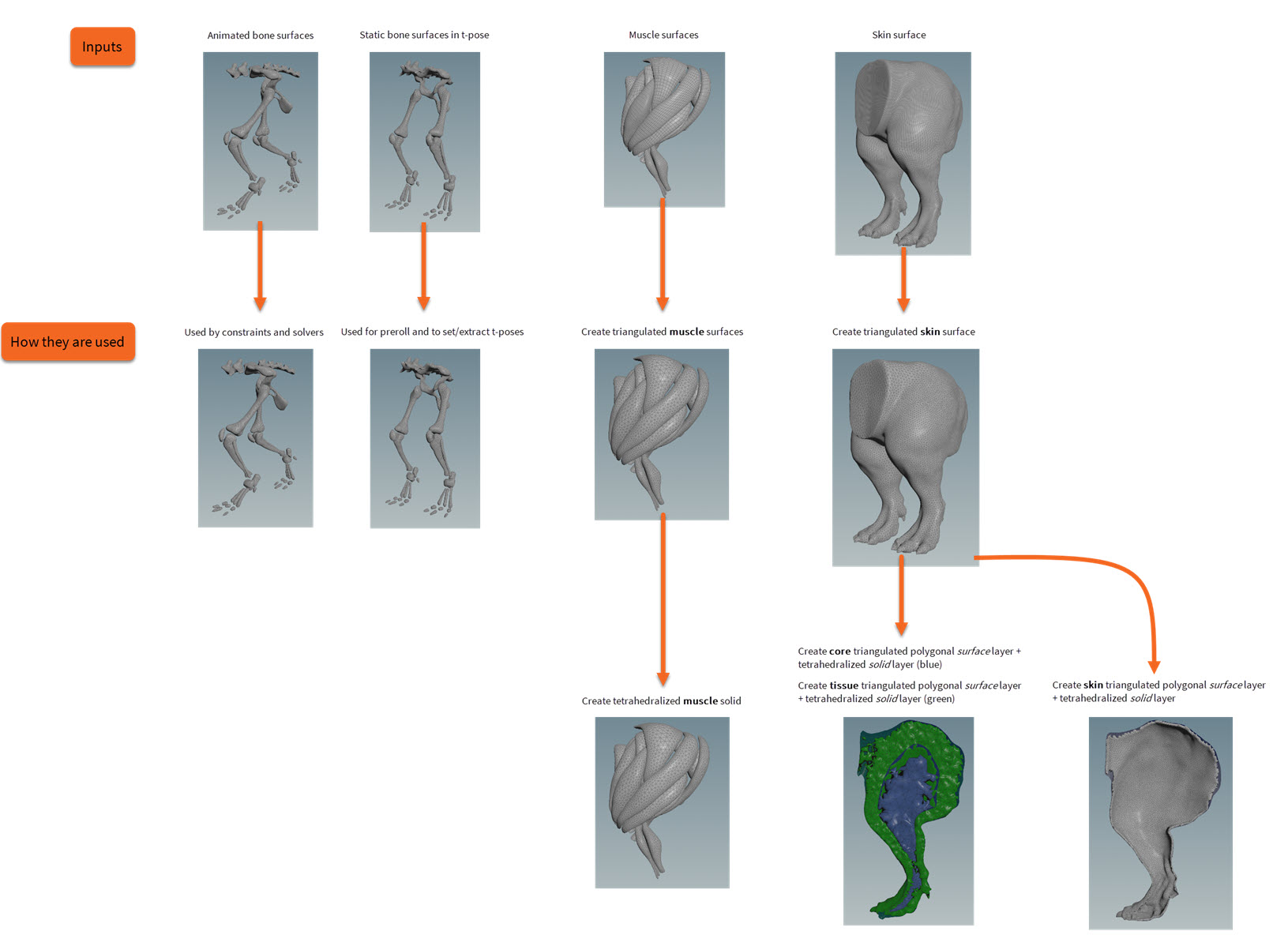
When working with the Muscle & Tissue system, your character will progress through three separate simulation passes leading to the final deformation of its renderable surface. At the end of each simulation pass, you will have the opportunity to save a geometry cache to disk before incorporating it into subsequent passes. The simulation passes are as follows: the muscles pass, the tissue pass, and the skin pass. The final stage of the Muscles & Tissue simulation creation process does not involve a simulation pass, but rather it requires that you use a geometry deformer to transfer your character’s final simulation to its high-resolution renderable mesh.
Each simulation pass does the following:
-
Operates on incoming solid softbody dynamic objects (objects comprised of tetrahedrons) and interprets attributes found on those objects to configure their physical properties and Vellum constraints. You can consider the majority of the Muscle & Tissue workflow as attribute manipulation that ultimately drives the constraint creation within the solvers.
-
Uses the output of the previous pass as its input so that it has animated static geometry to constrain to and to collide with. For example, in the first simulation pass—the muscles pass—the constraint geometry is supplied by the animated anatomical bones. This bone animation can be derived from a number of sources like a KineFX animation or an Alembic cache. It doesn’t matter how the bone animation was generated. The only requirement is that a static t-pose of the bones is available in conjunction with the animated bones. All muscle and tissue surfaces should always be created relative to their bones' static t-pose.
As you move your character through each of these passes, you will encounter three major concepts for the Muscle & Tissue system:
Simulation geometry 
Pass requirements 
Muscle pass
-
The
 Muscle Solidify SOP node requires:
-
Manifold non-intersecting polygonal muscle surfaces.
-
-
The
 Muscle Solver Vellum SOP node requires:
-
Solid muscles configured with physical property attributes and constraint attributes.
-
Animated bone surface geometry.
-
Tissue pass
-
The
 Tissue Solidify SOP node requires:
-
Skin surface.
-
Muscle simulation geometry cache.
-
Animated bone surface geometry.
-
(Optional) Core surface.
-
(Optional) Core falloff polylines.
-
-
The
 Tissue Solver Vellum SOP node requires:
-
Solid tissue configured with physical property attributes and constraint attributes.
-
Animated surfaces representing underlying muscle and bone animation.
-
Skin pass
-
The
 Skin Solidify SOP node requires:
-
Skin surface.
-
-
The
 Skin Solver Vellum SOP node requires:
-
Solid skin configured with physical property attributes and constraint attributes.
-
Animated surfaces representing underlying tissue animation.
-
Pass layers 
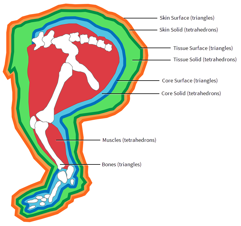
Even though each simulation pass operates on solid softbody dynamic objects (objects comprised of tetrahedrons), fused polygonal surfaces also play a role. For example, the Vellum Solver requires a polygonal surface as an attachment target for sliding constraints to have an effect. This is why each geometry layer includes both tetrahedrons and a polygonal surface enclosure.
The following Muscles & Tissue solidification nodes create the required primitive types:
Muscle pass
Muscles are generated by tetrahedralizing input muscle polygonal surfaces, creating one distinct muscle per connected piece. In the process of creating muscles, each connected piece is given an identifier attribute stored as muscle_id. If overlapping muscle surfaces share a common muscle_id value, then they are tetrahedralized as a merged entity. If overlapping muscle surfaces have distinct muscle_id values, then they are tetrahedralized separately and remain as overlapping objects. Polygonal surfaces for muscles are not created in the solidification step. Instead, the surfaces are created just-in-time within the ![]()
![]() Muscle Solver Vellum SOP node as they are only required for the Vellum sliding constraint.
Muscle Solver Vellum SOP node as they are only required for the Vellum sliding constraint.
Tissue pass
Tissue is generated using a layering approach. Perhaps the most complex object in the Muscle & Tissue system, the tissue solid is divided into two layers. The innermost tissue layer is referred to as the core, and the layer surrounding the core is just referred to as the tissue. Polygonal surfaces are created to envelop both the core tetrahedrons and the tissue tetrahedrons. As a result, the tissue pass is comprised of four distinct pieces of geometry: the tissue surface, the tissue solid, the core surface, and the core solid. The core plays an intermediary role in attaching tissue to muscle; it is firmly attached to the muscles and bones, and it serves as the attachment target for the tissue. The core also has the ability to respond to the scaling force by imparting an inward pull on tissue geometry in order to force it (by applying negative pressure) towards the muscles and bones.
Skin pass
Much like the tissue layer, the skin is generated as a solid—albeit a very thin solid—with a polygonal shell. Generating the skin object as a tetrahedral mesh, as opposed to only having a polygonal surface, provides greater opportunities to simulate a more fleshy appearance with thickness and substance. The solid component of the skin (skin solid) can relay physical properties like shape stiffness and volume preservation, while the polygonal surface (skin surface) can contribute stretch resistance to produce desirable wrinkling effects.
Attachments 
Understanding the relationship each simulation pass has with its associated attachment constraints is key when it comes to fine tuning your simulation results. Since multiple attachment constraints co-exist and affect the same geometry in tandem, it is important to familiarize yourself with each type of constraint operating on a piece of geometry in each simulation context.
Muscle constraints 
Muscle constraints are configured with the ![]()
![]() Muscle Properties SOP node and the
Muscle Properties SOP node and the ![]()
![]() Muscle Constraint Properties Vellum SOP node. These nodes take incoming solid muscle geometry, add or modify attributes, and then pass the data downstream.
Muscle Constraint Properties Vellum SOP node. These nodes take incoming solid muscle geometry, add or modify attributes, and then pass the data downstream.
Then the ![]()
![]() Muscle Vellum Solver SOP node applies these attribute values to either physical properties or attachment constraints in the following ways:
Muscle Vellum Solver SOP node applies these attribute values to either physical properties or attachment constraints in the following ways:
-
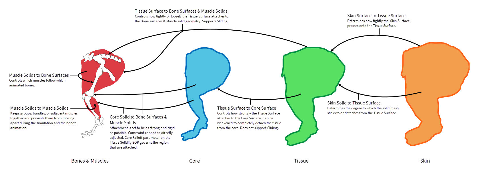
Muscles are attached to bones firmly in areas designated as Muscle Ends.
-
Muscles are attached with a springy sliding attachment to bones in areas designated to have Muscle to Bone attachments.
-
Muscle are attached to other muscles with a springy attachment via the Muscle to Muscle attachment.
-
Muscles are attached to other muscles with a firm, non-sliding attachment in areas designated to have Muscle Glue attachments.
In all cases, a firm attachment means it has a very high stiffness and will resist forces that try to pull it away from the rest position. Any other attachment is subject to a stiffness and damping ratio property that can affect its responsive and springy behavior.
Tissue constraints 
Tissue constraints are configured with the ![]()
![]() Tissue Properties SOP node. This node takes the incoming tissue geometry, adds and/or modifies its attributes, and then passes the data downstream. The
Tissue Properties SOP node. This node takes the incoming tissue geometry, adds and/or modifies its attributes, and then passes the data downstream. The ![]()
![]() Tissue Vellum Solver SOP node then uses these attribute values to create the necessary constraints.
Tissue Vellum Solver SOP node then uses these attribute values to create the necessary constraints.
Tissue is constrained in the following ways:
-
All core points are firmly attached to the muscle and bone input geometry.
-
The interior surface of the tissue layer (tissue solid) is attached to the exterior surface of the core layer (core surface).
-
The exterior surface of the tissue layer (tissue surface) is attached with a sliding attachment to the muscle and bone input geometry.
-
A distance limiting attachment also exists to restrict the exterior surface (tissue surface) from sliding too far.
In all cases, a firm attachment means it has a very high stiffness and will resist forces that try to pull it away from the rest position. Any other attachment is subject to a stiffness and damping ratio property that can affect its responsive and springy behavior.
Skin Constraints 
Skin constraints are configured with the ![]()
![]() Skin Properties SOP node. This node takes the incoming skin geometry, adds and/or modifies its attributes, and then passes the data downstream. The
Skin Properties SOP node. This node takes the incoming skin geometry, adds and/or modifies its attributes, and then passes the data downstream. The ![]()
![]() Skin Vellum Solver SOP node then uses these attribute values to create the necessary constraints.
Skin Vellum Solver SOP node then uses these attribute values to create the necessary constraints.
Skin is constrained in the following ways:
-
All interior skin (skin solid) points are attached and slide over the input tissue (tissue surface) geometry.
-
Exterior skin (skin surface) points have a separate sliding attachment to the tissue (tissue surface) geometry.
-
A distance limiting attachment also exists to restrict the skin surface from sliding too far.
Two separate attachment constraints exist for the skin pass so that you can adjust them independently. You can use the solid point attachment (on the skin solid) to adhere or loosen the connection between skin and the underlying tissue. If loosened enough, the skin can appear more like a loose fitting jacket surrounding the tissue. You can also use the exterior surface attachment (on the skin surface) to force the polygonal exterior to tighten itself up against the tissue and press deeper into crevices.
Forces 
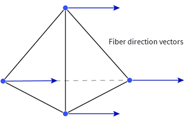
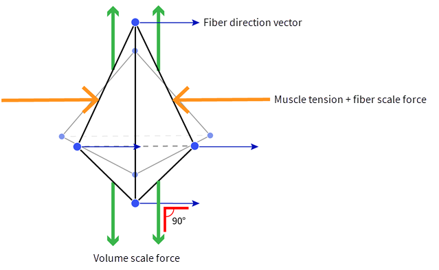
Muscle fiber scale force & muscle tension 
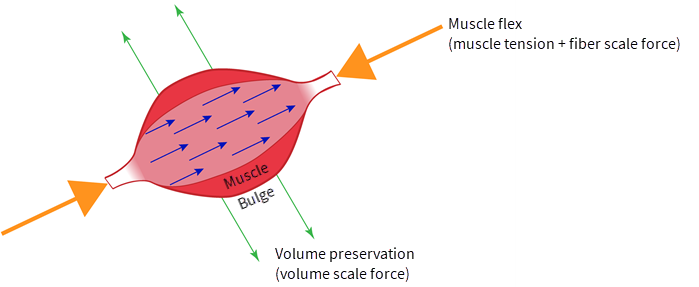
Muscles respond to a stiffness force along their local axes to produce an effect that is similar to muscle contraction. We refer to this action as fiber scaling. Since muscles are assigned a relatively high volume preservation stiffness by default, when fiber scaling is applied along their local axes, a volume-preserving bulging occurs perpendicular to these axes.
The main attributes that contribute to the fiber scaling action are:
-
muscletensionapplies fiber scaling to muscles and thereby activates them, and you can animate it from the Muscle Flex SOP node.
 -
fiberstiffnessprovides the fiber scale force or strength for the fiber scaling, and you can adjust it with the Fiber Strength parameter on the Muscle Properties SOP.
 -
materialWvector attribute controls the orientation of the local axis, and it can be groomed interactively using the Fiber Groom SOP node.
 -
fibervolumescaleboosts the volume preservation response when fiber scaling takes effect, and you can adjust it with the Fiber Volume Scale parameter on the Muscle Properties SOP.
Fiber scaling varies over the different regions of a muscle. Areas designated as tendon regions in the ![]()
![]() Muscle Properties SOP node will reduce the Fiber Strength, while the regions in the belly of the muscles will receive the full effect of the fiber scale force.
Muscle Properties SOP node will reduce the Fiber Strength, while the regions in the belly of the muscles will receive the full effect of the fiber scale force.
Important Note
Ultimately, the stiffness and responsiveness of fiber scaling actions are controlled by a combination of all the fiber parameters on the ![]()
![]() Muscle Properties SOP.
Muscle Properties SOP.
Volume scale or shrinkage 
The ![]()
![]() Tissue Properties SOP and
Tissue Properties SOP and ![]()
![]() Skin Properties SOP nodes have parameters that control tissue and skin shrinkage. In their rest positions (
Skin Properties SOP nodes have parameters that control tissue and skin shrinkage. In their rest positions (tpose attribute), the tissue, core, and skin record a rest volume and rest shape for each primitive in their geometries. Over the course of a simulation, the rest configuration can be modified relative to its initial state.
You can use the scale values for the rest shape and volume to adjust this rest configuration and create a shrink-wrapping effect that causes tissue and skin to pull inward and tighter against internal muscle and bone objects. By balancing the interplay between core, tissue solid, tissue surface, skin solid, and skin surface rest scales, you can achieve a variety of different tissue looks for your Muscles & Tissue simulation. For example, shrinking tissue tetrahedrons while expanding surface triangles can contribute to additional buckling over a tissue’s surface.
Sliding 
You can achieve a much more believable simulation if you apply sliding constraints to its attachments. With sliding constraints, surfaces and muscle objects are allowed to stay attached to internal geometry while having the freedom to slide the point of attachment relative to the initial state. Conversely, you can also use too much sliding to produce effects like muscles that flop every which way and tissue that oozes off the bone like a viscous fluid.
You can control the sliding for tissue and skin exterior surfaces (tissue surface and skin surface) with the Slide Rate and Slide Distance parameters on the ![]()
![]() Tissue Properties SOP and
Tissue Properties SOP and ![]()
![]() Skin Properties SOP nodes. Slide Rate affects the amount of change a re-projected target location is allowed to contribute to each time step during a solve. A Slide Rate of 1.0 allows a re-projection of a target attach location to update fully every time step, while a fractional slide rate only takes a percentage of the updated location vector. For more information on Vellum slide constraints, see Sliding Constraints.
Skin Properties SOP nodes. Slide Rate affects the amount of change a re-projected target location is allowed to contribute to each time step during a solve. A Slide Rate of 1.0 allows a re-projection of a target attach location to update fully every time step, while a fractional slide rate only takes a percentage of the updated location vector. For more information on Vellum slide constraints, see Sliding Constraints.
Nodes 
Property nodes
Core workflow 
The following sections outline the different network steps that are needed to create each pass in a Muscle & Tissue simulation.
Muscles pass 
In the first stage of Muscles & Tissue simulation creation, you create the muscle pass for the simulation. The muscle pass creates the solid muscle geometry that moves and flexes with the animated bone geometry, and then drives the majority of the tissue’s deformations (point transforms) downstream.
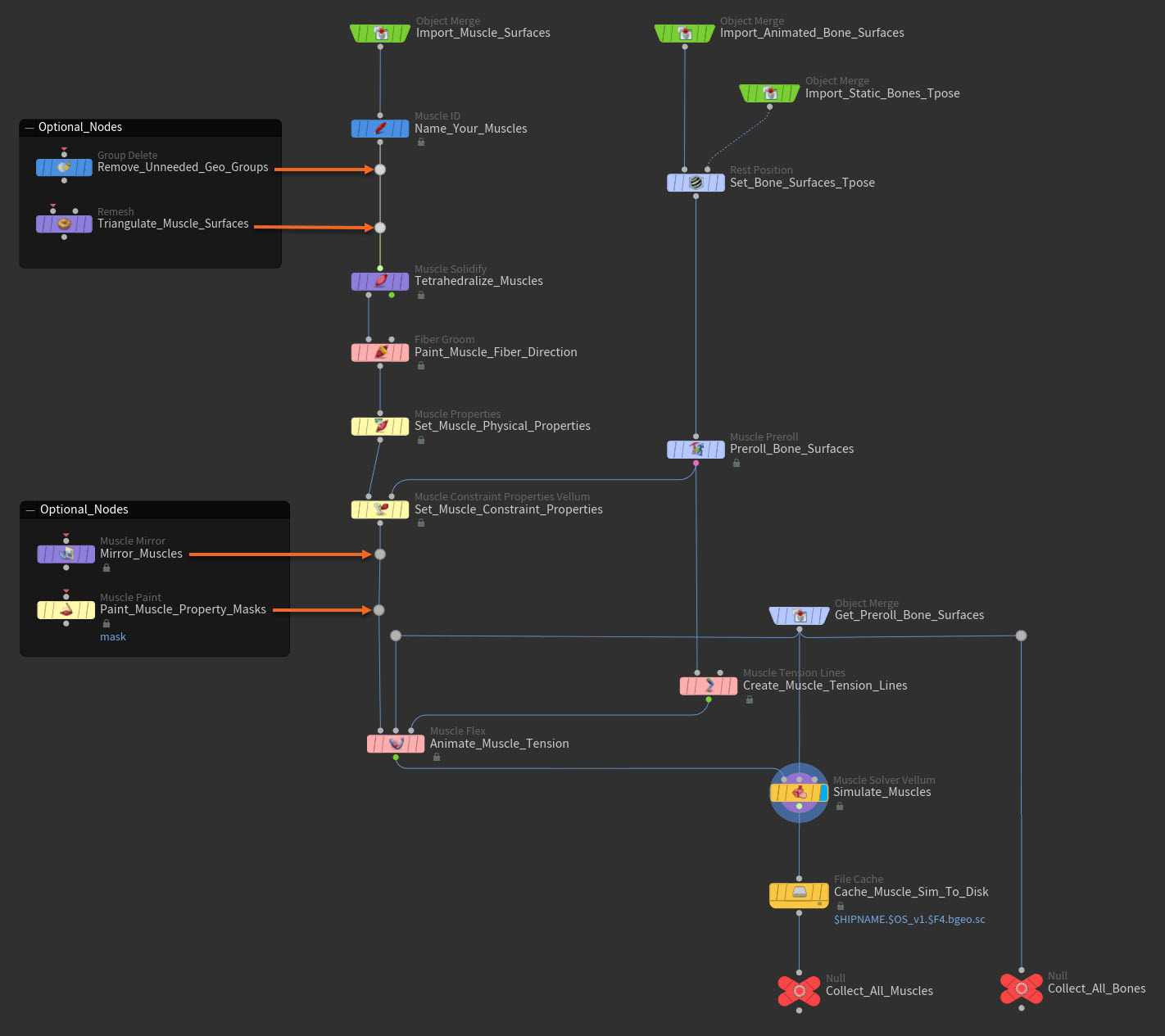
The following section lists the steps for recreating the example muscles network above. You can adapt these steps to create your own basic muscles pass from scratch.
-
Import the static muscle surfaces, animated bone surfaces, and static t-pose bone surfaces.
You need the static muscle surfaces, animated bone surfaces, and static t-pose bone surfaces for your character to be able to generate the solid muscles for the muscles pass.
There are many ways to bring in or import geometry with SOPs. For example, you can use an
 Object Merge SOP node, a
  File SOP, a
  Stash SOP, an
  Alembic SOP, and so on.
-
Import your muscle surface geometry. The sculpted muscle surfaces should be manifold non-intersecting polygonal geometry modeled in real-world scale (with 1 Houdini unit = 1 meter).
-
Import your animated bone surfaces. The polygonal bone surfaces should be modeled in real-world scale (with 1 Houdini unit = 1 meter).
-
Import your bone surfaces that are in their t-pose (rest position).
-
-
Name the muscles.
Each muscles surface (self-contained series of connected primitives) that will represent a muscle in your Muscle & Tissue simulation must have a
muscle_idattribute or name before it can be tetrahedralized.Create a
 Muscle ID SOP node, connect it to your static muscle surfaces import node, and then use the Muscle ID SOP to select each piece of your muscle surface geometry and assign them a Name.
 -
(Optional) Remove any unneeded geometry groups.
If you used geometry groups to select your muscle surfaces in step two, you no longer need those
groupattributes. You can remove them from your muscle geometry to make sure only necessary attributes are being passed to downstream nodes.Create a
 Group Delete SOP node, connect it to your Muscle ID SOP node, and then use the Group Delete SOP to select and remove the unneeded geometry groups from your muscles.
 -
Set the t-pose for the bone surfaces.
It is necessary to store the rest position or t-pose for your character’s bones and muscles as these values will be used to move your geometry into and out of the t-pose position throughout the Muscles & Tissue creation process.
-
Create a
 Set T-Pose SOP node and connect it to the static t-pose bone surfaces import node. The Set T-Pose tab menu item creates a
  Rest Position SOP node with preset store t-pose settings.
 -
Use the
Rest Position SOP to store the t-pose bone geometry’s current pose in the tposepoint attribute.
-
-
(Optional) Triangulate the muscles externally.
The skin surface must be triangulated before tetrahedralization. Traditionally this is done by using the Remesh Surface settings that are inside the
Muscle Solidify SOP node.However, if you want more control over how the muscle polygons are triangulated, then you can use an external
 Remesh SOP node to triangulate the muscles geometry.
Create a
Remesh SOP node, connect it to the Muscle ID SOP node, and then use it to triangulate the muscles geometry before building their tetrahedra. -
Triangulate and then tetrahedralize the muscle surfaces.
-
Create a
Muscle Solidify SOP node and connect it to the Muscle ID SOP node. -
Make sure that the input muscle surfaces are tessellated with clean equilateral triangles. The muscle surfaces must be triangulated before tetrahedralization. To do this, use the internal Remesh Surface settings on the Muscle Solidify SOP node.
-
The Muscle Solidify SOP node automatically tetrahedralizes the input triangulated muscle surfaces. The solid muscles do not have an outside polygonal surface like the tissue pass or skin pass because the muscles' surfaces are created just-in-time within the
Muscle Solver Vellum SOP node only when they are required by the Vellum sliding constraints. -
Adjust the Tissue Solidify SOP's parameter settings as you desire.
-
The Max Tet Size parameter sets the upper size limit for individual generated tetrahedra. The smaller the tetrahedra, the more detail the muscles will be able to convey to the tissue pass downstream. However, the bigger the tetrahedra, the faster the muscles' performance.
-
-
-
Groom muscle fiber direction.
When a muscle flexes, it contracts in the direction of its fiber vectors. The fiber vectors define the orientation of the muscles' local axes. For your muscles to contract in the direction you want them too, they need to have well defined custom fiber direction vectors. You can paint these fiber direction vectors for your muscles with the
Fiber Groom SOP node.Create a Fiber Groom SOP node, connect it to the Muscle Solidify SOP node, and then use it to interactively groom the fiber direction vectors for your muscles so that they flow in the direction you want your muscles to contract. These custom fiber vectors are then stored in the
materialWattribute, which is later used by the Muscle Flex SOP downstream. -
Set muscle physical properties.
The muscle physical properties determine the physical characteristics of the muscles like how receptive or resistant the muscles are to shape changes, which regions of the muscles are tendon, how stiff or floppy the muscles are, how much the muscles will bulge on contraction, and so on.
Create a
Muscle Properties SOP node, connect it to the Fiber Groom SOP node, and then configure the Muscle Properties SOP’s parameter settings as you desire.We recommend that you use the first Number of Assignments multiparm tab to set the general settings for all your muscles, and then use the subsequent multiparm tabs to set specific property configurations for individual muscles or groups of muscle.
Important Note
Please keep in mind that the Absolute and Relative versions of the parameters have different behaviors. The Absolute parameter values are applied as overrides, and the Relative parameter values are applied as multipliers of previously set values (from prior multiparm tabs) or default values.
-
Shape Stiffness determines how much a muscle wants to stay in its original shape (the
tpose). -
Damping Ratio determines how quickly a muscle’s shape can change.
-
Mass Density determines whether or not the number of tetrahedra in a muscle affects its overall mass or appearance in the simulation.
-
Fiber Strength determines how strongly a muscle is squeezed.
-
Fiber Damping controls how rapidly a muscle can contract.
-
Fiber Scale Range defines the min/max threshold of muscle tension for a muscle.
-
Fiber Volume Scale controls the volume scale force that is applied to a muscle tetrahedra when fully contracted.
-
Tendon Stiffness determines the scale factor that is applied to Shape Stiffness for the tendon regions of a muscle.
-
Tendon Mask Radius defines which parts of a muscle are the tendon regions.
-
Thickness Threshold defines the Tendon Stiffness threshold above which a muscle region is considered the belly of the muscle, and below which a muscle region is considered the tendon.
-
-
Preroll the bone surfaces.
Create a
 Muscle Preroll SOP node, connect it to the upstream bone surfaces t-pose node, and then add a hold and/or a preroll of frames that transitions your character’s bones from their t-pose to the their world space position at the first frame of their shot animation. Optionally, you can also enter the node’s viewport state and use the transform handles to add a transformation offset to the character’s bones preroll.
The transformation used to go from t-pose to start position is stored as
preroll_detail attributes on the output geometry. In the tissue pass and skin pass you will be able to reference this same transformation data using additional Muscle Preroll SOP nodes to move your character’s other components into the exact same position. -
Set muscle constraint properties.
The muscle constraint properties create and configure the constraints for the muscles. The muscle constraints attach the muscles to the bones and to each other, constrain the ends of the muscles, define the collision radii of the muscles, and determine how much velocity each muscle inherits from surrounding muscles.
Create a
 Muscle Constraint Properties Vellum SOP node, connect its first input to the Muscle Properties SOP node and its second input to the Muscle Preroll SOP node, and then set all its parameters values as you desire.
-
The Muscle Ends parameters determines whether the muscles ends are constrained to pre-animated positions or nearby bones. Which target the muscles ends attach to is determined by the Muscle Ends parameter on the
Muscle Vellum Solver SOP. -
The Muscle to Muscle parameters control how muscles are constrained to each other.
-
The Muscle to Bone parameters control how muscles attach to the bone geometry.
-
The Velocity Blend parameters controls how much neighborhood velocity is imparted to the muscles.
-
The Collisions parameters define the collision radii of the muscles.
Tip
You can use the Visualize buttons in the
Muscle Constraint Properties Vellum SOP node parameters to view visual representations of the different constraints' current settings in the viewport state. -
-
(Optional) Mirror your muscles.
If you only have half (just the left or right side, rather than both sides) of your character’s muscle geometry and your character is symmetrical, then you can use the
 Muscle Mirror SOP node to mirror or duplicate the muscles for the missing side.
-
Create a Muscle Mirror SOP node and connect it to the
Muscle Constraint Properties Vellum SOP node. -
In the Muscle Mirror SOP's parameters, specify the Naming prefixing and Mirror Plane position you want to use for the mirroring operation.
-
The Muscle Mirror SOP automatically creates the muscles for the missing side of your character and makes sure that all the mirrored muscles receive the proper names (
muscle_idattributes), fiber vectors (materialWattribute), and properties (physical and constraints).
-
-
(Optional) Paint tissue property masks.
If you want to paint masks on your muscles so that only certain muscle properties and values apply to certain regions on your muscles, then create an
 Muscle Paint SOP node, connect it to the Muscle Constraint Properties Vellum SOP node, and then use it to paint those regions.
You can paint the following preset muscle physical and constraint properties on your muscles:
-
Muscle Ends Mask lets you paint the End Regions for the Muscle Ends constraint on your muscles. This determines which area of your muscles the Muscle Ends constraint will affect.
-
Muscle to Bone Mask lets you paint the Stiffness for the Muscle to Bone constraint on your muscles. The brighter the heat map, the higher the stiffness. Stiffness determines how stretchy the Distance Threshold connection is.
-
Tendon Mask lets you paint the Tendon Mask Radius property on your muscles. Tendon Mask Radius defines which parts of a muscle are the tendon regions and how far from the muscle’s ends the tendon regions extend.
-
Muscle Glue lets you paint the Muscle Glue constraint values on your the muscles. The Muscle Glue constraint forms a rigid attachment between neighboring muscles so that they will never be able to separate.
-
Slide Rate lets you paint the amount of Slide Rate on your muscles. Slide Rate determines how much the Muscle to Bone constraint connections can drift along the surfaces of your bone.
-
-
Create muscle tension lines.
The triggering of muscle activation and the increase and decrease of
muscletensionin your muscles is automated by the muscle tension lines. Themuscletensionattribute drives the flexing action of your muscles during their simulation.The
 Muscle Tension Lines SOP node lets you draw the muscle tension lines on any static t-pose geometry (this is most commonly your bone geometry). The name of each muscle tension line is stored in the
 autoflex_idattribute, the initial length of each line is stored in therestlengthattribute, and the length of the line as it shortens and lengthens over the bone geometry’s animation is stored in thelengthattribute. The difference between therestlengthandlengthvalues are what drives the increase and decrease ofmuscletension.-
Create the Muscle Tension Lines SOP node, connect it to the bone surfaces preroll node, and then use it to create the muscle tension lines.
-
Draw each line on your static t-pose guide geometry (most commonly the bone geometry) making sure that the lines begin and end at the approximate origin and insertion points of each of the muscles.
Tip
You can use the Guides parameters to help you visualize your lines and their target guide geometry in the viewport state.
-
-
(Optional) Connect a geometry node or an import node that contains pre-drawn polylines to the second input on the Muscle Tension Lines SOP node to replace the internally generated muscle tension lines.
Note
You can use the muscle tension lines alone or in conjunction with keyframed
muscletensionvalues per muscle on the Muscle Flex SOP node. -
-
Get preroll bone surfaces.
You need the animated bone surfaces to drive the proxy animation in the
Muscle Flex SOP node, so you need to retrieve the data stored in the bone preroll node upstream.Create an
Object Merge SOP node and point it to the upstream bone preroll node. -
Animate the muscle tension.
-
Create a
Muscle Flex SOP node and connect its first input to the Muscle Constraint Properties Vellum SOP node, its second input to the bone preroll Object Merge SOP node, and its third input to the Muscle Tension Lines SOP node. -
Set the Muscle Flex SOP node’s parameter values as you desire.
-
Use the Activation Link parameters to link your muscle geometry (
muscle_idattribute) to themuscle tension lines (autoflex_idattribute) that drive their automatic flexion timing. -
Use the Muscle Tension Lines parameters to adjust the activation ratio between muscle tension line length (
restlengthandlengthattributes) and what is considered a fully flexed state for the muscles (muscletensionattribute). This sets the threshold for what is considered flexed or not. -
Use the Muscle Flex parameters to animate the
muscletensionattribute which is then used by themuscle solver to help determine when muscles try to contract and relax during their shot animation. This animation can be created automatically by the muscle tension lines alone or in combination with keyframes on the Muscle Flex parameters. You can tell the solver when to activate the muscles and when not to activate them by keyframing those parameter values.
-
-
-
Simulate the muscles.
Compute the tissue simulation using the Vellum solver.
-
Create a
Muscle Vellum Solver SOP node, connect its first input to the Muscle Flex SOP node, connect its second input to the bone preroll Object Merge SOP node, and then set all the parameter settings you desire for the solve.-
If your muscles use the Muscle Ends constraints, be sure to select how you want those constraints to behave with the Muscle Ends parameter on the Muscle Vellum Solver SOP node.
-
-
(Optional) If an animated
muscletensionattribute is not present on the muscle solver’s first input, you can connect flexing reference primitives to its third input to provide the animatedmuscletensionattribute directly. In this case, muscles will look for matchingmuscle_id's coming in from the third input, and then use themuscletensionattribute found on the first point.
-
-
Cache the muscles to disk.
Create a
 File Cache SOP node, connect it to the Muscle Vellum Solver SOP node, and then use it to cache the results of the muscles simulation to disk.
 -
Collect the muscles and bones.
Collect the final data outputs from the muscles pass for use downstream in the tissue pass.
-
Create two
 Null SOP nodes.
 -
Connect the first null to the
File Cache SOP node’s output to copy (collect) the final muscle simulation cache. -
Connect the second null to the bone preroll Object Merge SOP node to copy (collect) the prerolled animated bone geometry.
-
Tissue pass 
In the second stage of Muscles & Tissue simulation creation, you create the tissue pass for the simulation. The tissue pass creates the filler tetrahedra that surround the muscles and fill in the gaps between the muscles (core layer) and a thick tissue layer that functions as the base skin for your character. The tissue pass shows muscle definition and coarser skin wrinkling/creasing, whereas the downstream skin pass (detail skin) shows finer skin wrinkling/creasing and adds an additional level of detail to the outmost surface of your character’s Muscle & Tissue simulation. The core layer in the tissue pass also pulls in both the tissue layer and the skin pass with a sucking-type effect.
The tissue pass has two layers, and each layer is comprised of two separate geometry pieces. The composition of the tissue pass (from inner most to outmost) is the following:
-
The core layer
-
A tetrahedral solid core inner mesh (core solid)
-
A triangulated polygonal core outer surface (core surface)
-
-
The tissue layer
-
A tetrahedral solid tissue inner mesh (tissue solid)
-
A triangulated polygonal tissue outer surface (tissue surface).
-
Each of these layers have separate physical properties and constraints.
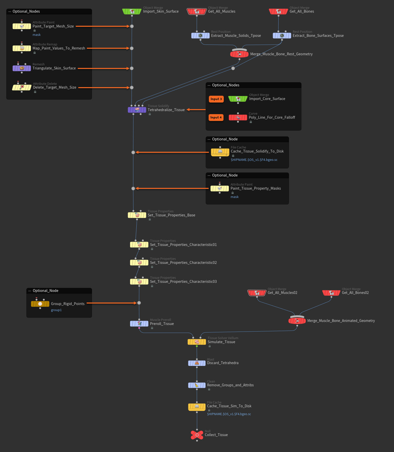
The following section lists the steps for recreating the example tissue network above. You can adapt these steps to create your own basic tissue pass from scratch.
-
Import the skin surface.
Import your original high-resolution skin surface geometry. You need this surface to generate the geometry for the tissue pass.
There are many ways to bring in or import geometry with SOPs. For example, you can use an
Object Merge SOP node, a File SOP, a Stash SOP, an Alembic SOP, and so on. -
Get the muscles simulation and animated bone surface outputs from the muscles pass.
Retrieve the muscles simulation and animated bone surface geometry outputs from the muscles pass. The
Tissue Solidify SOP node needs this geometry so that it can create the tissue’s tetrahedra.There are many ways to bring in or import geometry with SOPs. For example, you can use an
Object Merge SOP node, a File SOP, a Stash SOP, an Alembic SOP, and so on. -
Extract t-poses from the muscle solid and bone surfaces geometry.
Your character’s muscle simulation and animated bone geometry needs to be in their rest positions (t-poses) before you can create the tissue for your character.
Create an
Extract T-Pose SOP node for both the muscle solid geometry output import node and the bone surface geometry output import node, and then connect them to those nodes. The Extract T-Pose tab menu item creates a Rest Position SOP node with preset t-pose extract settings.-
Use one of the
Rest Position SOP nodes to extract the tposeattribute from the muscles simulation. -
Use the other
Rest Position SOP nodes to extract the tposeattribute from the animated bone geometry.
-
-
Merge the muscle simulation and bone surface output t-poses.
In order for the
Tissue Solidify SOP node to able to use both the muscle simulation output’s t-pose and the animated bone surface output’s t-pose, you need to merge their point transform rest data.Create a
 Merge SOP node and then connect both the muscle simulation output’s t-pose node and the animated bone surfaces output’s t-pose node to the Merge SOP node.
 -
(Optional) Triangulate the tissue surface externally.
The skin surface must be triangulated before tetrahedralization. Traditionally this is done by using inside the Remesh Surface settings that are inside the
Tissue Solidify SOP node. However, if you want more control over how the skin surface polygons are triangulated—especially if you are concerned about the scale of the triangles—then you can use an external Remesh SOP node and complimentary attribute nodes to triangulate the skin surface’s geometry.Create and use the following nodes:
-
Create an
 Attribute Paint SOP node, connect it to the skin surface geometry’s import node, type the name of the target mesh size attribute you want to use in the Attribute Name parameter field, and then use the node to paint the target mesh size attribute values on the tissue surface to affect the scale of the triangles.
 -
Create an
 Attribute Remap SOP node, connect it to the Attribute Paint SOP, set its Original Name parameter value to the same attribute you defined in the Attribute Paint SOP, and then use it to map the target mesh size painted values to the desired minimum and maximum values you'd like to use in the Remesh SOP node.
 -
Create a
Remesh SOP node, connect it to the Attribute Remap SOP node, and the use it to triangulate the skin surface geometry before building the tetrahedra. -
Create an
 Attribute Delete SOP node, connect it to the Remesh SOP node, and use it to delete the target mesh size attribute you created with the Attribute Paint SOP as it is no longer needed in the Muscle & Tissue workflow.
-
-
Triangulate the tissue surface internally and then tetrahedralize it.
-
Create a
Tissue Solidify SOP node, connect the Merge SOP node to its Input 2, and then connect the imported bone surface geometry’s Extract T-Pose SOP node to its Input 4. -
Make sure that the input skin surface is tessellated with clean equilateral triangles. The skin surface must be triangulated before tetrahedralization. To do this, use the internal Remesh Surface settings on the Tissue Solidify SOP node.
-
The Tissue Solidify SOP node automatically constructs the skin pass from the triangulated input skin surface geometry. The tissue pass is made up two layers, which in turn are composed of two geometry pieces each: a core layer with a tetrahedral solid core mesh (core solid) and a triangulated polygonal core surface (core surface), and a tissue layer with a tetrahedral solid tissue mesh (tissue solid) and a triangulated polygonal tissue surface (tissue surface).
-
Adjust the Tissue Solidify SOP's parameter settings as you desire.
-
The Surface Offset parameter specifies the distance to inset this surface prior to tetrahedralization. This offset distance is intended to give some allowance for the skin pass downstream.
-
The Tissue Relative Thickness parameter controls how deep to build the tissue solid relative to the local depth of the space enclosed by the skin surface.
-
The Core Falloff parameter creates a weight mask attribute that represents the distance from the core surface layer to the geometry provided on the Tissue Solidify SOP node’s
Input 4. Thiscorefalloffattribute is also used by the downstream Tissue Vellum Solver SOP node when stiffening the attachment constraint between the core solid and the muscles and bones.
Notes
-
In most cases, the Surface Offset value should match the value of the Skin Thickness parameter on the
Skin Solidify SOP node downstream. However, this is not a requirement. -
(Optional) You can supply external core surface geometry with the
Input 3on the Tissue Solidify SOP node if generating it procedurally isn’t sufficient. If you supply your own core surface, then it will override the Tissue Relative Thickness parameter’s value. -
(Optional) You can supply custom poly lines for the core’s falloff with the
Input 4on the Tissue Solidify SOP node. These lines determine from where the sucking in force emanates to pull the tissue in towards the muscles and bones. This force’s strength is determined by the Rest Scale parameter on the Tissue Properties SOP node.
-
-
-
(Optional) Cache the tissue geometry to disk.
We recommend that you save your tissue geometry to disk instead of cooking it each time you touch your tissue pass network.
Create a
File Cache SOP node, connect it to the Tissue Solidify SOP node, and then use it to cache the results of the tissue’s tetrahedralization. -
(Optional) Paint tissue property masks.
If you want to paint masks on your skin so that only certain skin properties and values apply to certain regions on your skin, then create an
Attribute Paint SOP node, connect it to the Tissue Solidify SOP node, and then use it to paint those regions. You can then use the Mask Attributes parameter on individual Tissue Properties SOP nodes to apply specific skin property settings to the mask regions you painted. -
Set tissue properties.
Create a base
Tissue Properties SOP node that sets the general settings for all of your tissue, and then create individual Tissue Properties SOP nodes that each set tissue settings that contribute to a specific look or characteristic you want in the tissue. For example, you could create a Tissue Properties SOP to define the settings for tight tissue, and then create a separate Tissue Properties SOP to define the settings for saggy tissue.Since the tissue pass is made up of two geometries, the tissue surface and the tissue layer, there are also two sets of constraints that operate on the outer and inner tissue and connect it to the underlying core layer.
-
The tissue surface and tissue solid parameters are separated into their own tabs. On both tabs you can find material property parameters that affect Shape Stiffness, Volume Stiffness, Damping Ratio, and Mass Density.
-
The attachment parameters in the Tissue Surface Layer tab control how tightly or loosely the tissue surface will attach to the muscles and bones within your character. This constraint is also affected by the Sliding parameters.
-
In a similar fashion, the attachment parameters in the Tissue Solid Layer tab control the attachment of the innermost boundary points of the tissue solid tetrahedra to the core surface. This attachment constraint does not slide, but it can be weakened as much as desired to detach the tissue from the core completely or have it remain adherent.
-
When the attachment Rest Scale parameter’s value is set to less than 1.0, it will pull the tissue in towards the muscles and bones.
-
Sliding Rate determines how freely the attachment can slide.
-
Distance Limit creates a distance limit constraint that determines how far a point on the tissue surface can slide relative to its initial attachment point in the t-pose.
-
Limit Stiffness specifies the stiffness of the spring that imposes the distance limit.
-
Damping Ratio controls how sluggish vs. how springy the Distance Limit constraint is.
-
You can affect the Rest Scale for each of the tissue layer’s components (triangles and tetrahedra) with these parameters. During the tissue simulation, the tissue’s components will attempt to achieve this scale (relative to the t-pose rest state) and shrink or expand accordingly.
See the
Tissue Properties SOP node doc for detailed descriptions of each parameter. -
-
(Optional) Make areas of your tissue rigid.
If you need parts of your tissue to attach as rigidly as possible to the tissue’s surface layer and ignore sliding, then create a
 Group Create SOP node, connect it to the Tissue Solidify SOP node, and then use it to define a rigid skin point group in your tissue pass network.
If you define a rigid skin point group, then you also need to also enter the Group Name you defined on the Group Create SOP in the Advanced tab ▸ Rigid Group parameter field on the
Tissue Solver Vellum SOP node downstream.Tip
Periodically you may want to
 blast away portions of your character’s tissue to simulate a subsection for testing purposes. In situations like this, the points on the periphery of the deletion may become unconstrained and free-fall or slide undesirably (for example, imagine a sleeve of tissue sliding right off a limb). In these situations, we recommend that you use a point group like this to temporarily anchor the severed tissue regions and prevent the rest of the tissue from being affected adversely.
 -
Preroll and hold the tissue.
Move the tissue pass to its start position in its character’s shot animation. The tissue needs to be in the correct world space position and pose before computing the tissue simulation.
Create a
Muscle Preroll SOP node, connect it to the last Tissue Properties SOP in your chain of properties nodes, and then use it to move your tissue pass to its start position and hold its position. This node should match the transforms from the upstream bone preroll from your muscles set-up.Even though the tissue pass is static and not changing over time, the Muscle Preroll SOP node takes advantage of its ability to match the transforms that the muscles and bones have undergone while transforming from the t-pose rest position to the shot start frame position.
-
Get the muscle solid and bone surface outputs from the muscles pass.
Retrieve the muscle solid geometry and bone surface geometry outputs from the muscles pass. This geometry is animated and has the preroll baked in. The
Tissue Solver Vellum SOP node needs this geometry so that it can simulate the tissue.There are many ways to bring in or import geometry with SOPs. For example, you can use an
Object Merge SOP node, a File SOP, a Stash SOP, an Alembic SOP, and so on. -
Merge all muscle and bone output geometry.
In order for the
Tissue Solver Vellum SOP node to able to use both the muscle solid output’s t-pose and the bone surface output’s t-pose, you need to merge their geometry.Create a
Merge SOP and then connect both the muscle solid output’s import node and the bone surfaces output’s import node to the merge node. -
Simulate the tissue.
Compute the tissue simulation using the Vellum solver.
Create a
Tissue Solver Vellum SOP node, connect the upstream tissue preroll node to its Input 1and the merge node to itsInput 2, and then set all the parameter settings you desire for the solve. -
Clean up the tissue simulation.
Create a
Blast SOP node and connect it to the Tissue Solver Vellum SOP node.And then create a
 Clean SOP node and connect it to the Blast SOP node.
Use the Blast SOP and Clean SOP nodes to remove the solid (tetrahedral) component of the tissue (since you no longer need it) and any attributes you no longer need. However, be sure to keep the
tposeattribute as it is used in the later stages of the Muscles & Tissue simulation process. -
Cache your tissue simulation to disk.
Create a
File Cache SOP node, connect it to the Clean SOP node, and then use it to cache the results of the tissue simulation to disk.
Skin pass 
Once you have finished simulating the tissue for your character, you have the option to create a skin pass for your character. The skin pass allows you to create an addition tissue layer for your character that adds an additional level of detail to its outmost surface that you can’t achieve with the tissue pass alone. For example, by varying both the skin’s properties and solver settings, you can create skin effects like fine wrinkling and crepeing or delicate folds and creases.
The skin pass is comprised of two separate pieces of geometry:
-
A triangulated polygonal skin outer surface (skin surface)
-
A tetrahedral solid skin inner mesh (skin solid).
By building the skin pass with this added thickness, buckling, folding, and dynamic effects can behave more like a fatty epidermal layer and less like a layer of cloth.
Important Note
You do not have to create a skin pass for your character. You can achieve many skin looks with just the tissue pass. We recommend that you only use a skin pass when you need fine details on the outer surface of your character. If you choose not to create a skin pass, then use the simulation cache from your tissue pass when you transfer the results of your Muscle & Tissue simulation to your original high-resolution skin geometry.
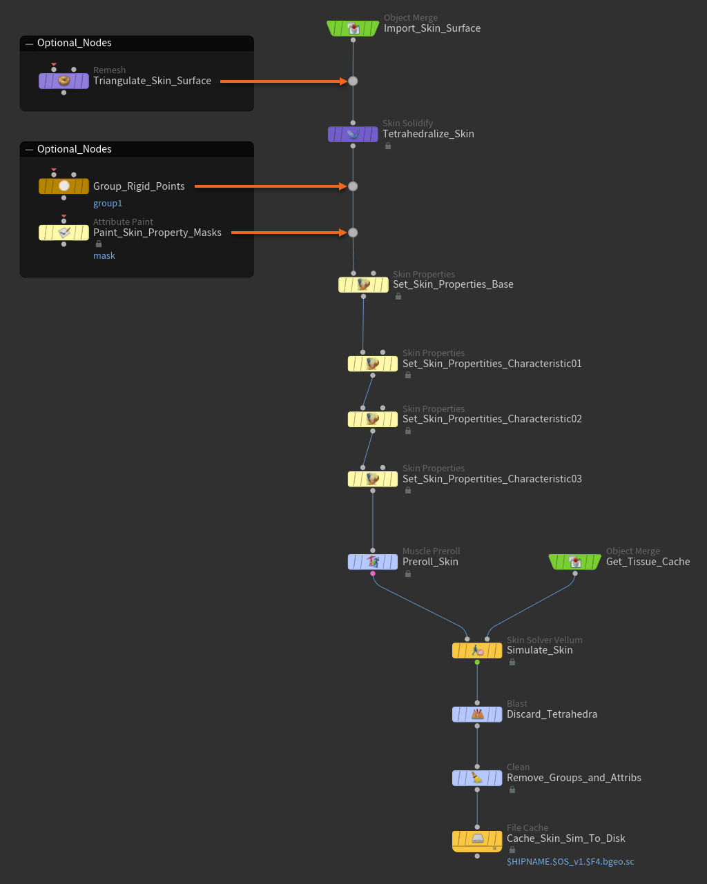
The following section lists the steps for recreating the example skin network above. You can adapt these steps to create your own basic skin pass from scratch.
-
Import skin surface geometry.
Import your original high-resolution skin surface geometry. You need this geometry to generate the skin pass.
There are many ways to bring in or import geometry with SOPs. For example, you can use an
Object Merge SOP node, a File SOP, a Stash SOP, an Alembic SOP, and so on. -
(Optional) Remesh the skin surface externally.
The skin surface must be triangulated before tetrahedralization. Traditionally this is done by using inside the Remesh Surface settings that are inside the
Skin Solidify SOP node.However, if you want more control over how the skin surface polygons are triangulated, then create an external
Remesh SOP node, connect it to the skin surface import name, and use it to triangulate the skin surface’s geometry. -
Triangulate the skin surface and then tetrahedralize it.
-
Create a
Skin Solidify SOP node and connect it to the high-resolution skin surface geometry’s import node. -
Make sure that the input skin surface is tessellated with clean equilateral triangles. The skin surface must be triangulated before tetrahedralization. If it is not triangulated, then use the internal Remesh Surface settings on the Skin Solidify SOP.
-
The Skin Solidify SOP node automatically constructs the skin pass from the triangulated input skin surface geometry. The skin pass is made up of two separate geometry pieces: a polygonal outer surface (skin surface) and a tetrahedral solid inner mesh (skin solid).
-
Adjust the Skin Solidify SOP's parameter settings as you desire.
-
The Skin Thickness parameter specifies how deep the skin solid layer should be.
-
The Regular Layers parameter determines how many layers of tetrahedrons are packed into the skin’s overall thickness.
Note
In most cases, the Skin Thickness value should match the value of the Surface Offset parameter on the
Tissue Solidify SOP node upstream. However, this is not a requirement. -
-
-
(Optional) Make areas of your skin rigid.
If you need parts of your skin to attach as rigidly as possible to the tissue’s surface layer and ignore sliding, then create a
Group Create SOP node, connect it to the Skin Solidify SOP node, and then use it to define a rigid skin point group in your skin network.If you define a rigid skin point group, then you also need to also enter the Group Name you defined on the Group Create SOP in the Advanced tab ▸ Rigid Group parameter field on the
Skin Solver Vellum SOP node downstream.Tip
Periodically you may want to
blast away portions of your character’s skin to simulate a subsection for testing purposes. In situations like this, the points on the periphery of the deletion may become unconstrained and free-fall or slide undesirably (for example, imagine a sleeve of tissue sliding right off a limb). In these situations, we recommend that you use a point group like this to temporarily anchor the severed tissue regions and prevent the rest of the skin from being affected adversely. -
(Optional) Paint skin property masks.
If you want to paint masks on your skin so that only certain skin properties and values apply to certain regions on your skin, then create a
Attribute Paint SOP node, connect it to Skin Solidify SOP node, and then use it to paint those regions.You can then use the Mask Attributes parameter on individual Skin Properties SOP nodes to apply specific skin property settings to the mask regions you painted.
Tip
You can paint a thickness multiplier attribute to vary the skin’s thickness. To do this, turn on the Thickness Multiplier Attribute parameter on the
Skin Solidify SOP node upstream and then specify the name of the attribute you want to paint with. By default, this attribute is skinthickness. Then on the Attribute Paint SOP node, create a Attributes tab ▸ Attributes multiparm and type the attribute’s name in its the Attribute Name parameter field. -
Set the skin properties.
Create a base
Skin Properties SOP node that sets the general settings for all of your skin, and then create individual Skin Properties SOP nodes that each set skin settings that contribute to a specific look or characteristic you want in the skin. For example, you could create a Skin Properties SOP to define the settings for sliding skin, and then create a separate Skin Properties SOP to define the settings for loose skin.Since the skin pass is made up of two layers, the polygonal surface outer layer and the tetrahedral mesh inner layer, there are also two sets of constraints that operate on the skin and connect it to the underlying tissue.
-
The Surface Layer tab has all the parameters that affect how the skin surface attaches to the tissue as well as the physical properties of its triangles. To determine how tightly the skin surface will press onto the underlying tissue’s surface layer, adjust the Attach Stiffness, Damping, and Rest Scale parameter settings.
-
The Solid Layer tab has similar parameters that apply to the tetrahedra in the skin solid. To determine the degree to which the skin solid sticks to or detaches from the underlying tissue surface, adjust the Attach Stiffness, Damping, and Rest Scale parameters.
-
You can also adjust the the parameters in the Sliding and Shrinkage tabs to adjust those behaviors respectively.
See the
Skin Properties SOP’s node doc for detailed descriptions of each parameter. -
-
Get the tissue simulation cache.
Retrieve the tissue simulation cache’s data. The
Skin Solver Vellum SOP needs this geometry to compute the skin simulation.There are many ways to bring in or import geometry with SOPs. For example, you can use an
Object Merge SOP node, a File SOP, a Stash SOP, an Alembic SOP, and so on.If your cached tissue geometry does not have a built-in preroll, then also create one with a
Muscle Preroll SOP node so that the tissue is in its start position before the skin simulation is computed. -
Preroll and hold the skin.
Move the skin pass to its start position in its character’s shot animation. The skin needs to be in the correct world space position and pose before computing the skin simulation.
Create a
Muscle Preroll SOP node, connect it to the last Skin Properties SOP in your chain of properties nodes, and then use it to move your skin pass to its start position and hold its position. This node should match the transforms from the upstream bone preroll from your muscles pass. -
Simulate the skin.
Compute the skin simulation using the Vellum solver.
Create a
Skin Solver Vellum SOP node, connect the upstream skin preroll node and the tissue cache import node to it, and then set all its parameter settings you desire for the solve.When simulating the skin pass, it is important to understand the following constraint relationships:
-
The skin surface is constrained to the tissue surface. Collisions and sliding are enabled for this constraint relationship.
-
The skin solid’s interior points are constrained to the tissue surface. Collisions are disabled and sliding is enabled for this constraint relationship. However, a distance-limiting spring attachment restricts sliding from exceeding the Distance Limit set on the
Skin Properties SOP node. This means that the skin surface’s sliding is restricted indirectly by the stiffness of the skin solid.
-
-
Clean up your skin.
Create a
Blast SOP node and connect it to the Skin Solver Vellum SOP node.And then create a
Clean SOP node and connect it to the Skin Solver Vellum SOP node.Use the Blast SOP and Clean SOP nodes to remove the solid (tetrahedral) component of the skin (since you no longer need it) and any attributes you no longer need. However, be sure to keep the
tposeattribute as it is used in the final stage of the Muscles & Tissue set-up process. -
Cache your skin simulation to disk.
Create a
File Cache SOP node, connect it to the Clean SOP node, and then use it to cache the results of the skin simulation to disk.
Simulation transfer 
Once you have completed simulating your character’s Muscles & Tissue simulation, you can then transfer all the point transformations from the tissue (if you did not use a skin pass in your set-up) or skin simulation to the high-resolution mesh you will be using in your shot.
To transfer the simulation generated point transforms to your high-resolution mesh:
-
Import your original high-resolution skin surface geometry (the original mesh you used to create the tissue and skin passes) and then also fetch the simulation cache from your skin simulation.
There are many ways to bring in or import geometry with SOPs. For example, you can use an
Object Merge SOP node, a File SOP, a Stash SOP, an Alembic SOP, and so on. -
Use an
Extract T-Pose SOP node to extract the t-pose for your character’s skin from the node you used to fetch the skin simulation cache. This will give you the rest position (tposeattribute) that you can then use for the point deform operation. -
Transfer the point transforms from your skin simulation cache to your character’s original high-resolution skin surface geometry with the
 Point Deform SOP node.
If your original surface had UVs, textures, and so on, they are preserved as the Point Deform SOP only uses the simulation output to deform the original mesh.
Tip
You can adjust the Point Deform SOP’s parameters to vary the final look of your character’s skin by introducing more or less averaging (blurring) into the point transforms.