Introduction
Hi there! My name is Paul Ambrosiussen and I’m a 3D Technical Artist focusing on Tool Development to support effective art pipelines, and optimize tool and workflow quality for the artists around the world I’m working with. I studied International Game Architecture and Design at NHTV University of Applied Sciences in Breda, Netherlands. While there, I found my passion in helping others create amazing things in a better, faster and more flexible way. Which is exactly what I am currently doing at my job at SideFX with Houdini – including creating tutorials, giving live lectures, attending events and presenting custom workshops to customers.
In this article I’d like to teach you about Lens Shaders and some of the things you can do with them. Due to the scope of the article it will not explain every single piece of code in detail, but should get you far enough to kickstart your own experiments. Lens Shaders can be pretty complex, but they can also be a lot of fun. There isn’t a lot of documentation on Lens Shaders in Houdini, so this will help you get a good understanding. The main examples used in this article revolve around Game Development, but are applicable to anyone doing rendering.
Why Lens Shaders for GameDev?
An important question to answer before getting into the details on how Lens Shaders work is “Why do we need Lens Shaders for GameDev??”. That’s a fair question, and deserves good answers. I will name a few before starting with the how and what.
Rendering 360 Content
One of the first things that come to mind when talking about lens shaders is 360 content. To render out this type of content we need a special type of lens, since we can’t just distort a regular image so that it works in a 360 context such as for Facebook 360deg Videos or Skyboxes. We need to render all sides around a camera to visualize the entire scene. This can either be done through a cross or latlong approach. We will be exploring the latlong method in the examples below.
Rendering Impostor Texture Sheets
Another application is an approach on how to optimize the rendering process of Texture Sheets used for Impostors. The examples in this article will cover what the benefits of this are, and what the use of Impostors entail.
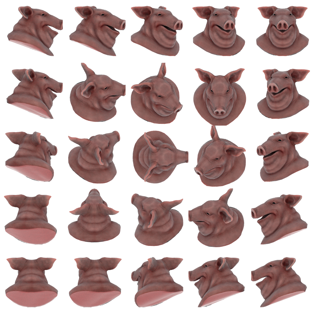
This is an example of an Impostor Texture Sheet. The Hemi-Octahedral example in the article will be used to render the above texture.
Texture / Lightmap Baking
Lens Shaders can also be used for texture or lightmap baking. Eetu on OdForce has a thread where he covers a clever approach on how to bake a lightmap from a scene using Lens Shaders.
The above shows some of the images Eetu provided in his thread. This use of lens shaders will not be covered in this article, but for those interested I recommend checking out his post here: https://forums.odforce.net/topic/8471-eetus-lab/?do=findComment&comment=132784
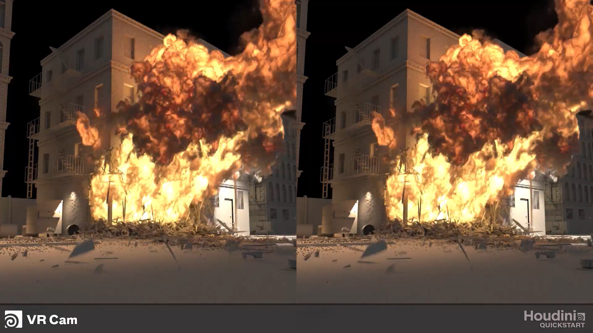
Rendering VR
Understanding Lens Shaders
To understand what effect a Lens Shader has on the default virtual camera lens, we first need to understand what process is being done for every single pixel on your render. Please note that this explanation has been simplified for simplicity sake, which should hopefully help you understand it a bit better.
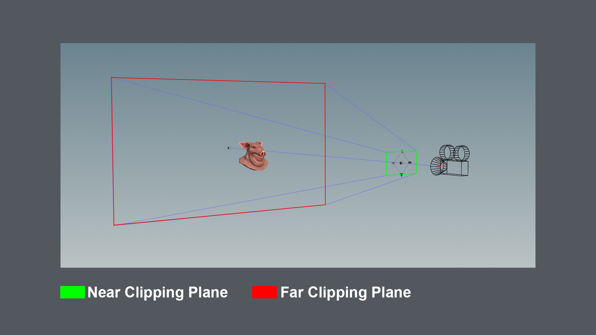
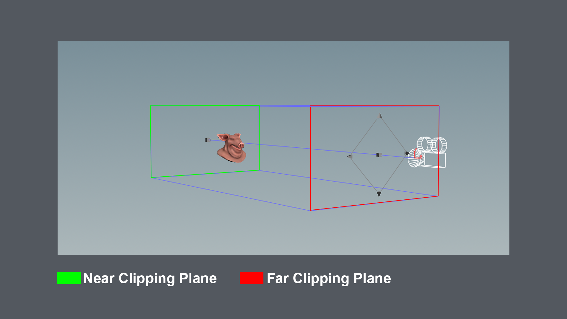
So to start with, let's look at the near and far clipping plane for a camera set to perspective mode. As shown in the image above the near clipping plane has been marked in green, while the far clipping plane has been marked in red. In the most simplified case where we exclude reflections and all the other fun stuff, everything in the volume between those two clipping planes could potentially be visible in the render. Why is this important you might ask? Well our Lens Shader is going to be modifying how our camera ray traces, hence affecting what that volume looks like.
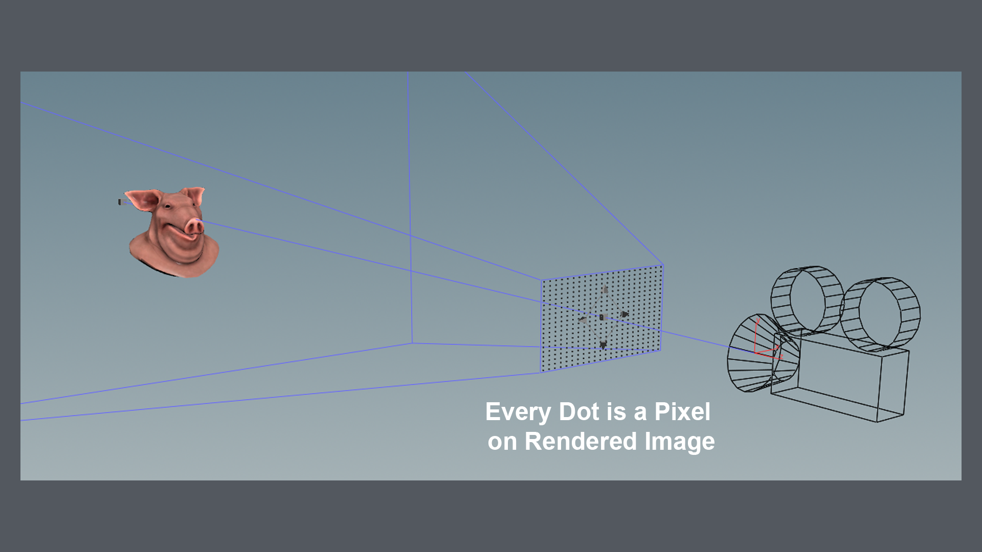
Imagine we took a blank canvas with the desired resolution we would like to be rendering (ex 1920x1080px), and aligned that with the camera near clipping plane. That’s what is being visualized in the image above. To give the pixels on our image a value, we will need to cast a ray from those pixel positions into a specific direction. That’s what our Lens Shader will be defining: 1. Where will I be casting my ray for the current pixel from? 2. In what direction will my ray for the current pixel go?
So the definition:
A Lens Shader is responsible for computing primary rays from screen coordinates, and is a flexible way to define new kinds of camera projections that can’t be modeled as perspective or orthographic projections.
Those two things are defined with variables in our Lens Shader.
vector P – Ray origin for pixel in camera space
vector I – Ray direction for pixel in camera space
The definition tells us those two are defined in camera space. So they will always be the same relative to our camera regardless of where we move or rotate our camera to. Those two vectors will also get the same transformations applied like our camera. Nice and easy. We will get into an example soon.
Understanding The Functionality (CVEX)
Creating a CVEX operator
To be able to use a lens shader, we need to create a special type of operator. It needs to be an operator which can contain CVEX on the Code tab of your HDA. CVEX is VEX code that runs outside a context. CVEX doesn’t have predefined variables, since it is just a program that Houdini calls with certain arguments (usually corresponding to points or data on points). This also means no context-specific functions such as geometry manipulation functions are available to the script.
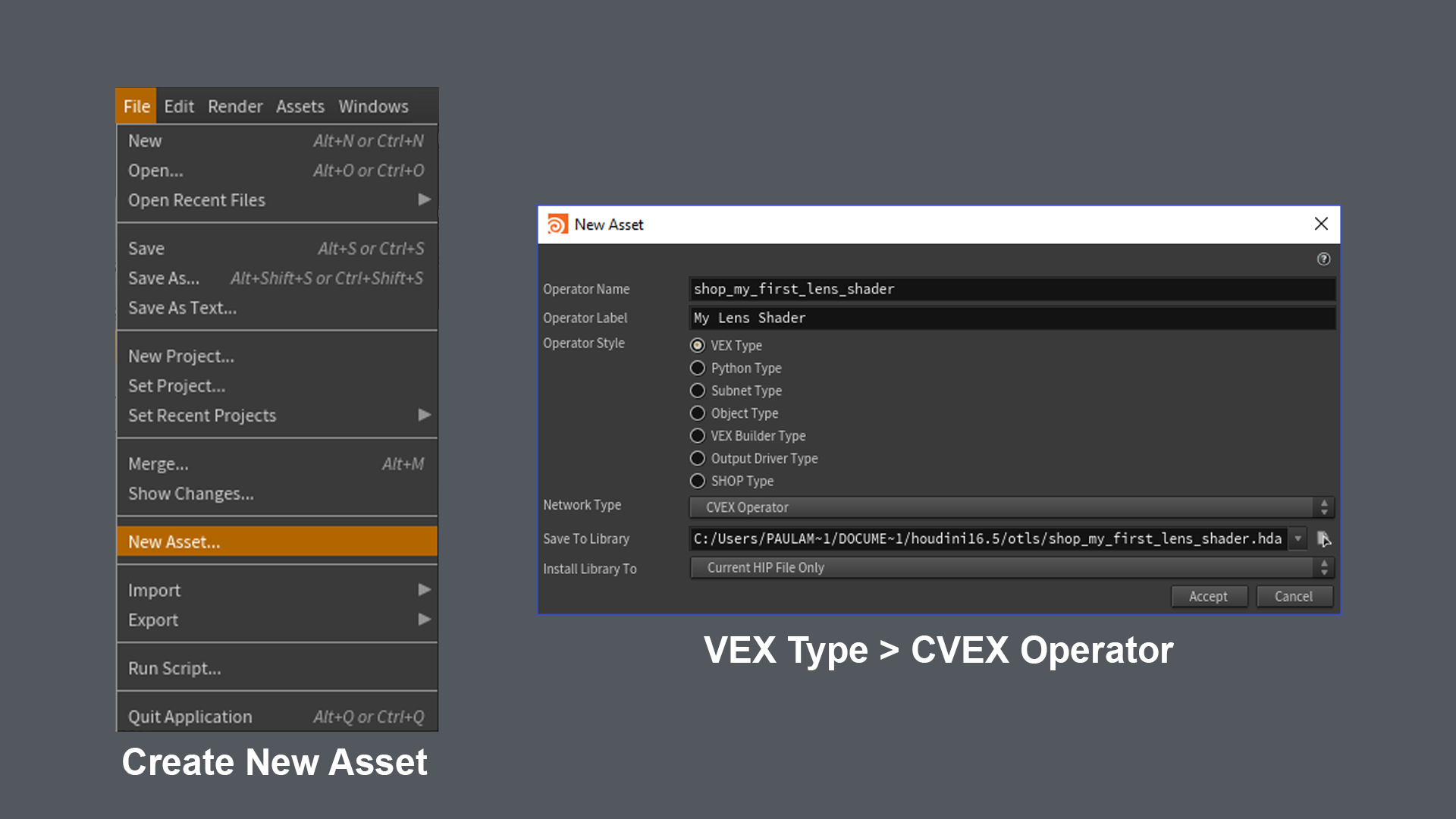
The image above shows how to create the operator which will contain the lens shader written in CVEX. Simply press New Asset in the file menu, and set the operator style to VEX Type. This will allow you to set the Network Type to CVEX Operator. A “Contextless VEX” operator.
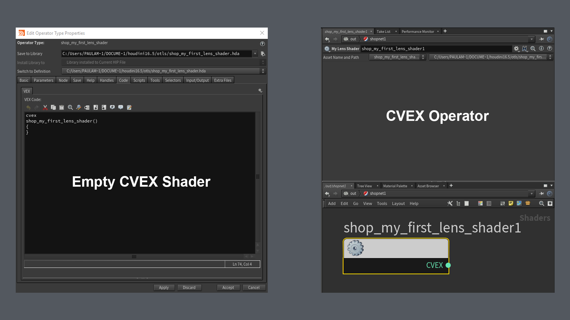
Once you have created the operator you should get the above window pop up. You might have noticed the code tab is usually disabled on most type HDAs. The Code tab is only available for applicable HDAs, like script-based shaders, vops, and python-based HDAs. Houdini will also already have created the body of your Lens Shader function. This is where we will be adding our logic. The name of the CVEX function does not matter. It will simply call whatever function has the cvex return type.
Parameters
Lens shaders can have the following parameters and exports by default:
- float x – X screen coordinate in the range -1 to 1
- float y – Y screen coordinate in the range -1 to 1
- float Time – Sample time
- float dofx – X depth of field sample value
- float dofy – Y depth of field sample value
- float aspect – Image aspect ratio (x/y)
- export vector P – Ray origin in camera space
- export vector I – Ray direction in camera space
- export int valid – Whether the sample is valid for measuring
The lens shader should be able to handle x and y values outside the -1 to 1 range, in case samples outside the image need to be generated. The P and I exports should be created in camera space, ignoring the camera transform like mentioned before.
If we then look at the lens shader we can see it will look like this:
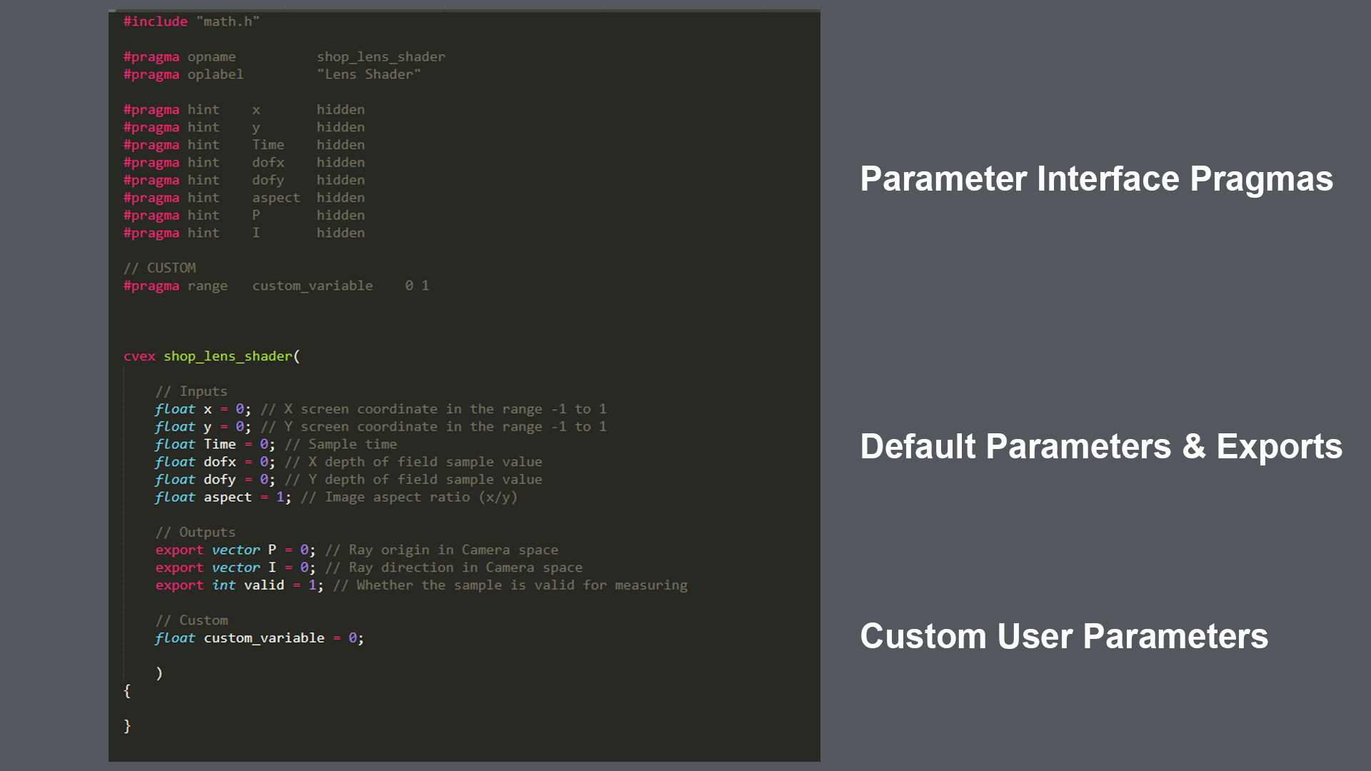
The input values have all been initialized to 0, except for the aspect variable. It doesn’t really matter what we set them to, since Houdini will set the values for us on render time. X for example will be set to a value between -1 and 1, depending on where the currently processed pixel is located on the image. -1 for the leftmost border pixels, 1 for the rightmost border pixels. Same for Y. 1 for the top, -1 for the bottom. Note that this means that our render is technically square. (We’ll see how to fix that later) We can however define custom parameters and variables, which is what the custom_variable is. To read more about how to construct the interface, visit: http://www.sidefx.com/docs/houdini/vex/pragmas.html
Once we have this, we can start building our own custom logic.
Assigning the Lens Shader to our Camera
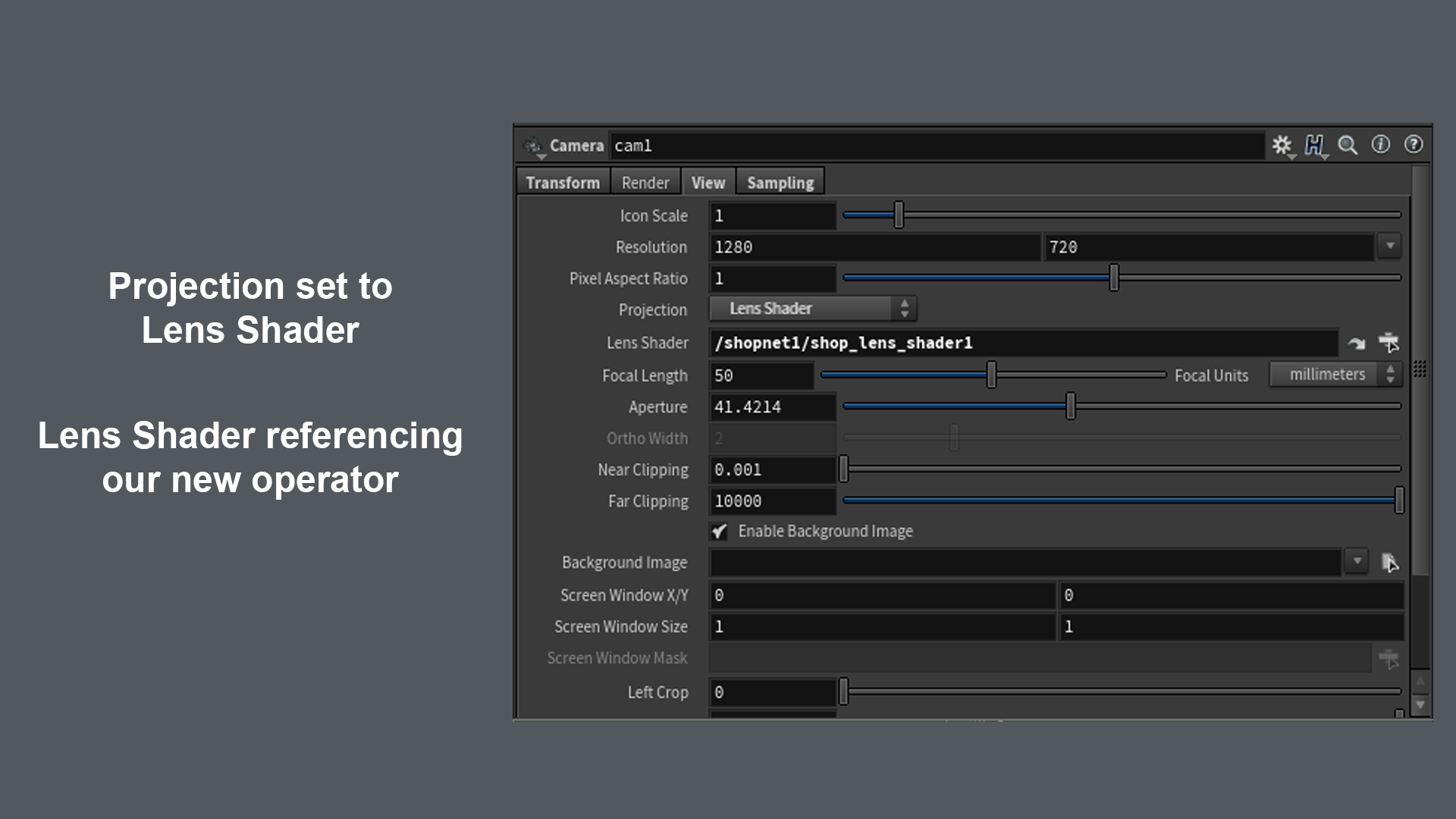
Getting the camera to use our custom Lens Shader is really easy. We just set our Camera Projection Mode to “Lens Shader”, and link our created Lens Shader in the corresponding parameter field.
Lens Shader Examples + Code
We will start with the most straightforward example: Orthographic Projection. The camera in Houdini ships with this mode, but it’s a good one to run through. Similar to the programmer “Hello World” equivalent.
Orthographic
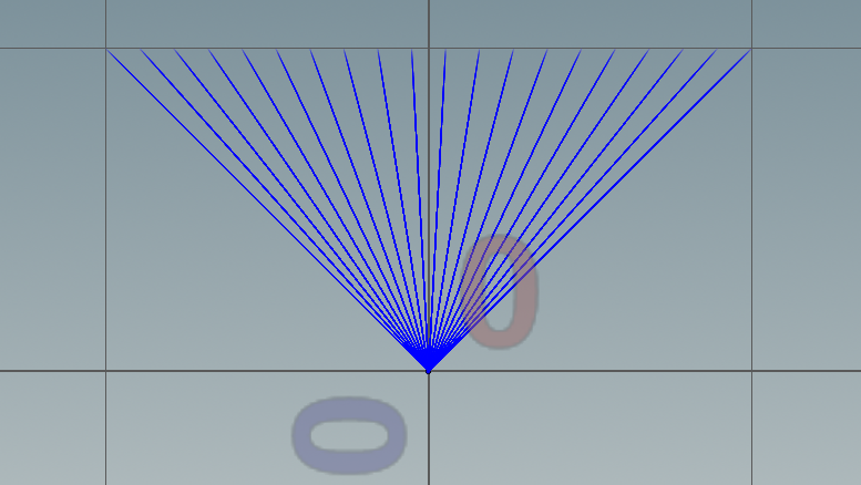
If we look at the Camera Frustum of a camera set to Orthographic we can see that the near and far clipping plane have the exact same size. This means that regardless of how close to the camera our subject is, it will always appear to be the same size in the render. So in terms of lens shader this should basically mean that the ray origin for our pixels will just be their initial position (X; Y; 0). For our Ray direction we can just use (0, 0, 1), since we’re looking straight ahead.
If we visualize our pixel positions and ray directions on a grid of points it should look like this:

Our code would look like the following:
{
######## Orthographic Projection ########
P = set(x, y, 0);
I = set(0,0,1);
}
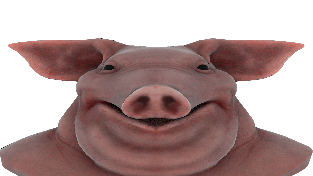
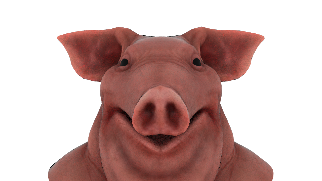
If we render that we can indeed see we rendered our subject in orthographic mode, but the pig head seems a bit squashed in Y. This is because we don’t account for the aspect ratio of our output render. We are rendering a 1920x1080 image meaning it has an aspect ratio of 16:9. This means we need to modify P to account for that. This can be done by simply dividing our y component of P by the aspect ratio.
Our code will now become:
{
######## Orthographic Projection ########
P = set(x, y / aspect, 0);
I = set(0,0,1);
}
This result looks much more accurate. The only thing remaining now is to implement the zoom functionality so that we can change how big the subject in the render is. Rather easy, since we just need to scale P by the amount we would like to zoom. This needs to be done in code, since moving a camera closer or further away does not affect the size of the subject when rendering Orthographic.
float zoom = 1; // User Variable
{
######## Orthographic Projection ########
P = set(x / zoom, y / (zoom * aspect), 0);
I = set(0,0,1);
}
Perspective
If we look at the Camera Frustum of a camera set to Perspective, we can see that the far clipping plane is much bigger than the near clipping plane. This means that the closer an object is to the near clipping plane, the bigger it will be on our render. For a perspective render we can just set our P to 0. Just like a pinhole camera. For our Ray direction we can just use (0, 0, 1 + lens distortion).
If we visualize our pixel positions and ray directions on a grid of points it would look like this:
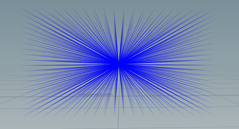
The code for this would look like:
float curvature = 0.0; // User Variable
{
######## Perspective ########
P = set(0, 0, 0);
I = set(x / zoom, y / (zoom * aspect), 1 + (1 - 2*(x * x + y * y)) * curvature);
}
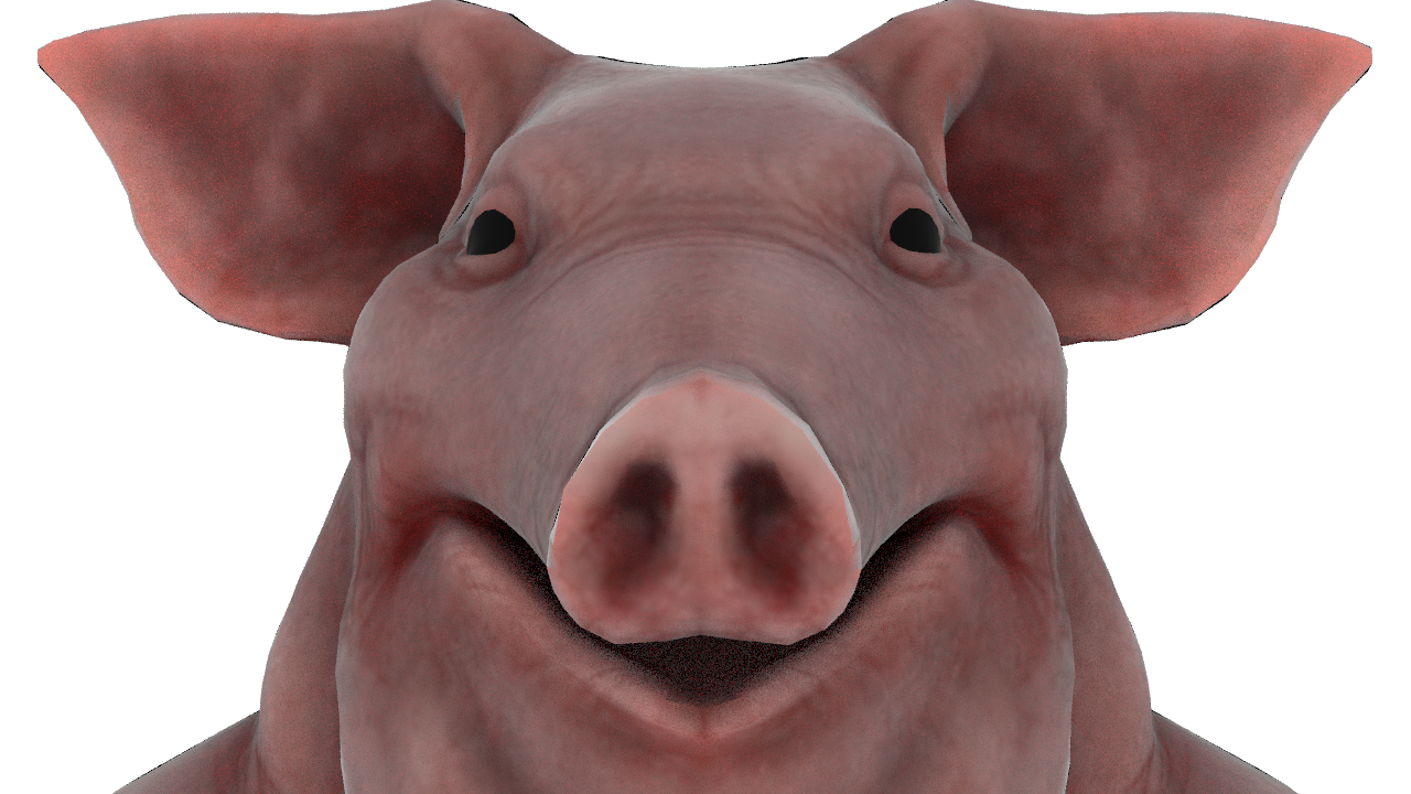
We can see that our pig head has become much less flat. It has some actual depth to it. The ears are a bit smaller than in the orthographic projection, since distance to camera now has an actual effect on the output. We can increase or decrease this effect by moving the camera closer or further away, together with the zoom & curvature parameter.
Polar (Panoramic)
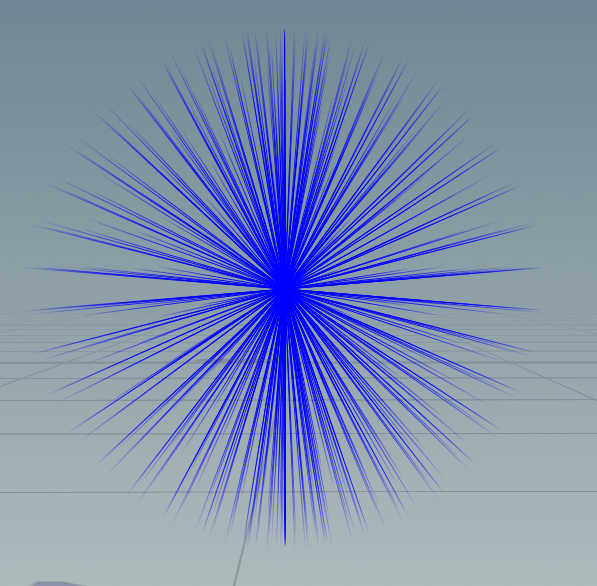
Our next example is the Polar Projection lens. We are basically going to take our flat grid of ray origin positions. ((x; y) from -1 to 1) and move them all to {0, 0, 0} for P. But to get the lens we need, we will need to have our grid of pixels all get I (ray direction) point outwards so that we get the polar projection we are after. This will essentially allow us to render everything in the scene around our camera, which we will call a lat-long image. To achieve this we will use the following spherical / polar math:
{
######## Polar Projection ########
float xa = -PI*x;
float ya = (0.5*PI)*y;
float sx = sin(xa);
float cx = cos(xa);
float sy = sin(ya);
float cy = cos(ya);
P = set(0, 0, 0);
I = set(cx*cy, sy, sx*cy);
}
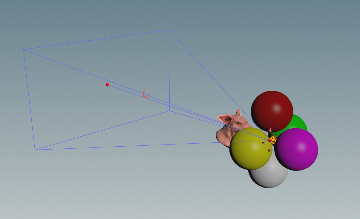
This is the scene we will be using to test our polar projection code. We can see that the pig head is in front of the camera, together with some coloured spheres placed all around the camera. We pretty much have objects on every side of the camera, including above and underneath it. If our logic works like it needs to, we should be able to see everything around the camera, regardless of which side it is located on.
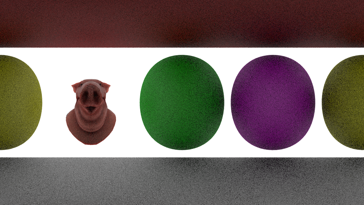
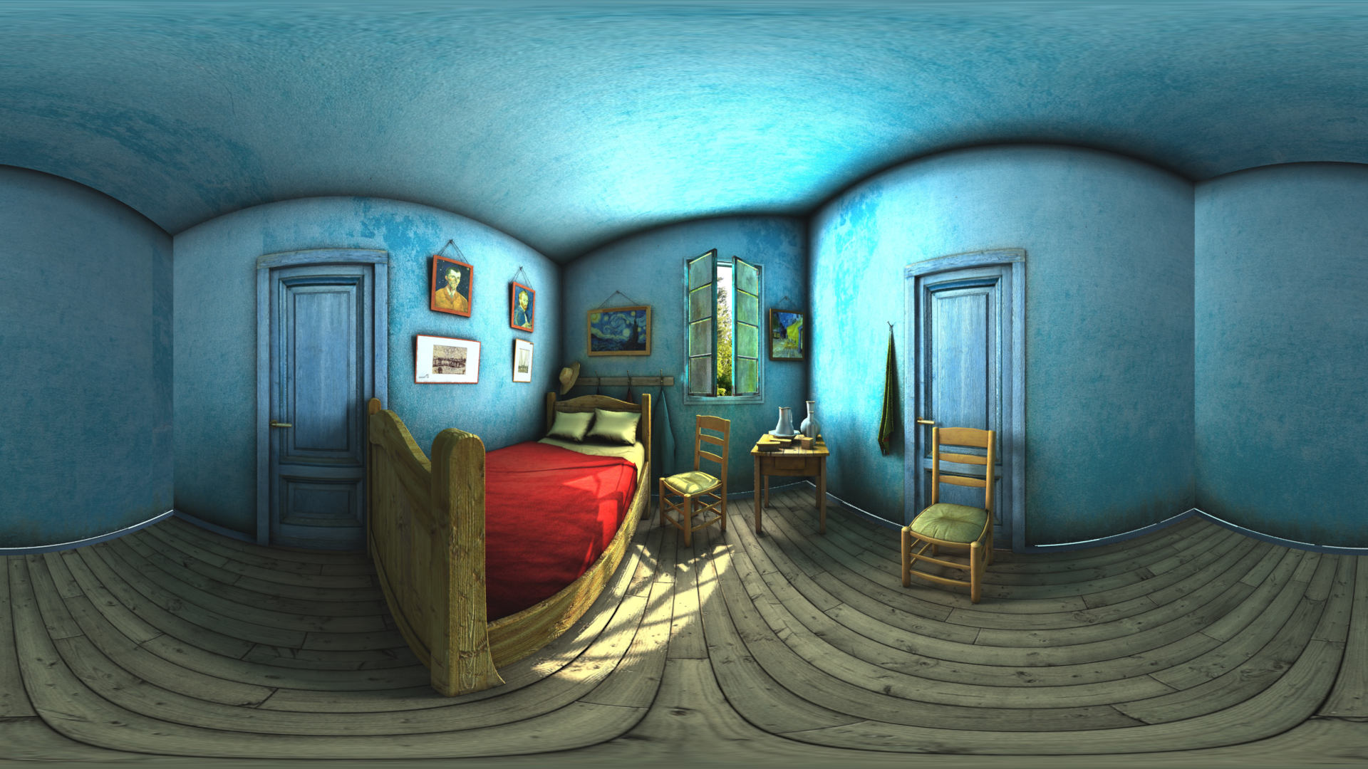
The first image above is the lat-long image we rendered using our code. As stated above we can indeed see everything in the scene around our camera, regardless of which side it is located on. The image however has some heavy distortion on the regions that have been rendered with the poles of the lens, but that won’t be too noticeable on our sphere when we apply it as a texture on a sphere containing uvs made with a polar projection as well. The result of that render applied on a sphere with polar projection UVs can be seen on the image above. This lens is rather useful when rendering skydomes or distant geometry in a scene you would like to consolidate.
Cylindrical (Curved)
Our next example is the Cylindrical lens. We are basically going to take our flat grid of ray origins. ((x; y) from -1 to 1) and bend that so that it resembles a cylinder. Using the cylinder_amount we can control how much of a cylinder it becomes. cylinder_amount of 0 results in all points on the X axis to be squashed together, while 1.0 results in a full cylinder. Values between 0.0 and 1.0 would result in everything in between, such as 0.5 being half a cylinder. This would basically allow us to render everything around the camera orthographically. Note that the code below has the X and Y component set to 0 while the image above does not because of visualization purposes.
The code for this is:
float cylinder_amount = 1; // User Variable
{
######## Cylinder Projection ########
float offset = 2 * PI * cylinder_amount;
float HalfPI = 0.5*PI;
float theta = fit(x, -1, 1, 0, offset);
P = set(0, y, 0);
I = set(cos(theta - (offset*0.5) + HalfPI), 0, sin(theta - (offset*0.5) + HalfPI));
}
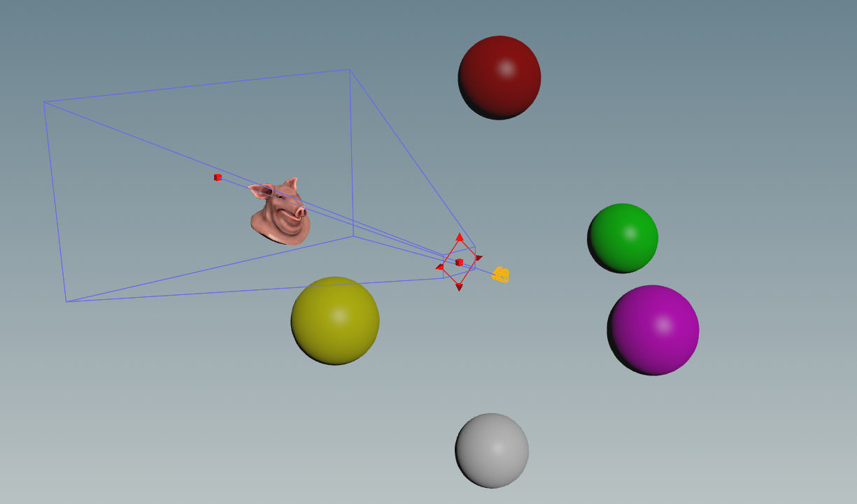
This is our scene. We can see that the pig head is in front of the camera, together with some coloured spheres around the camera. If our logic works like it needs to we should be able to see everything located on all sides of the camera when cylinder_amount is set to 1. (Except for what’s above and underneath)
In the gif above we can see what the render looks like when slowly sliding the cylinder_amount slider from 0 to 1. The closer it gets to 1, the more we can see. Which in the end even results in the purple sphere behind the camera to be fully visible.
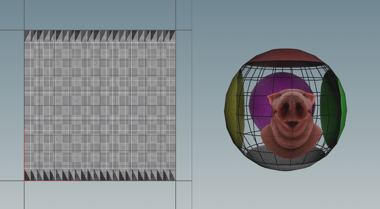
Texture Atlas (Hemi-Octahedron)
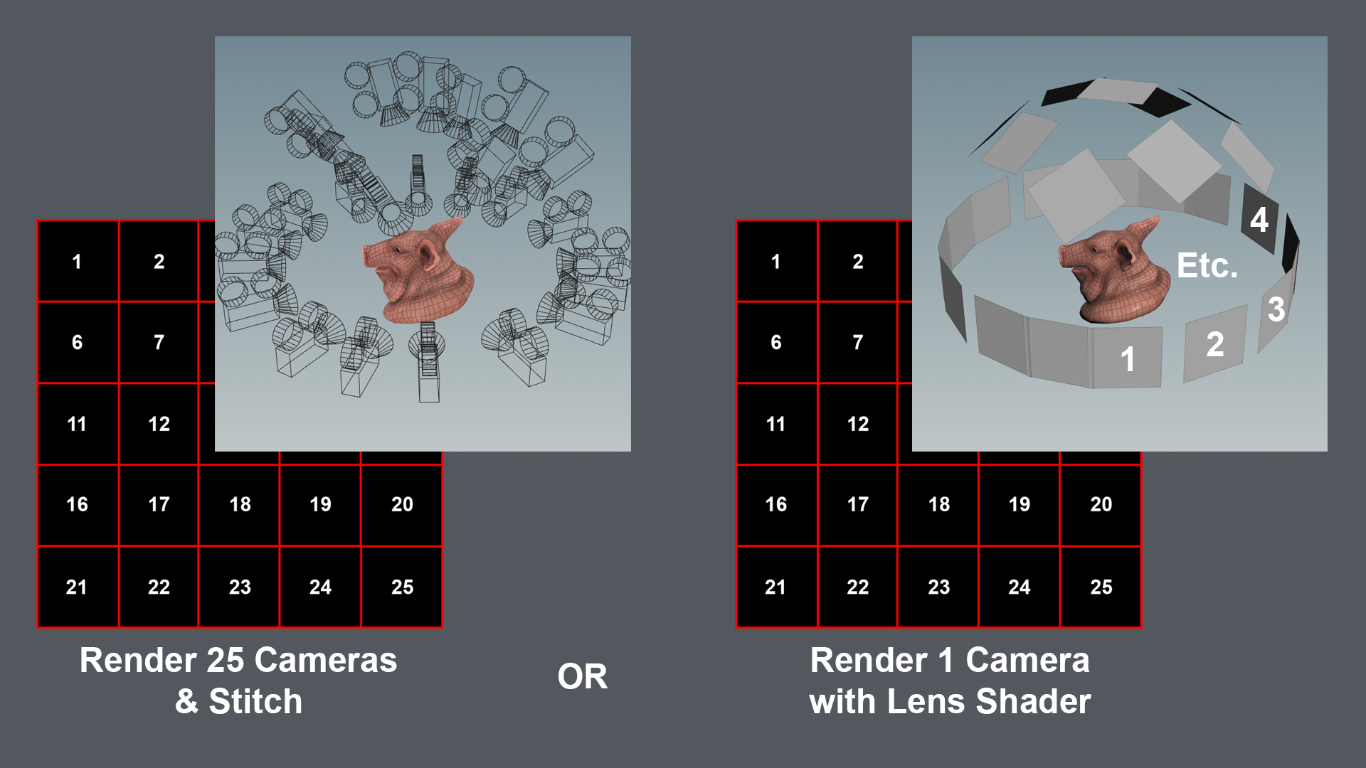
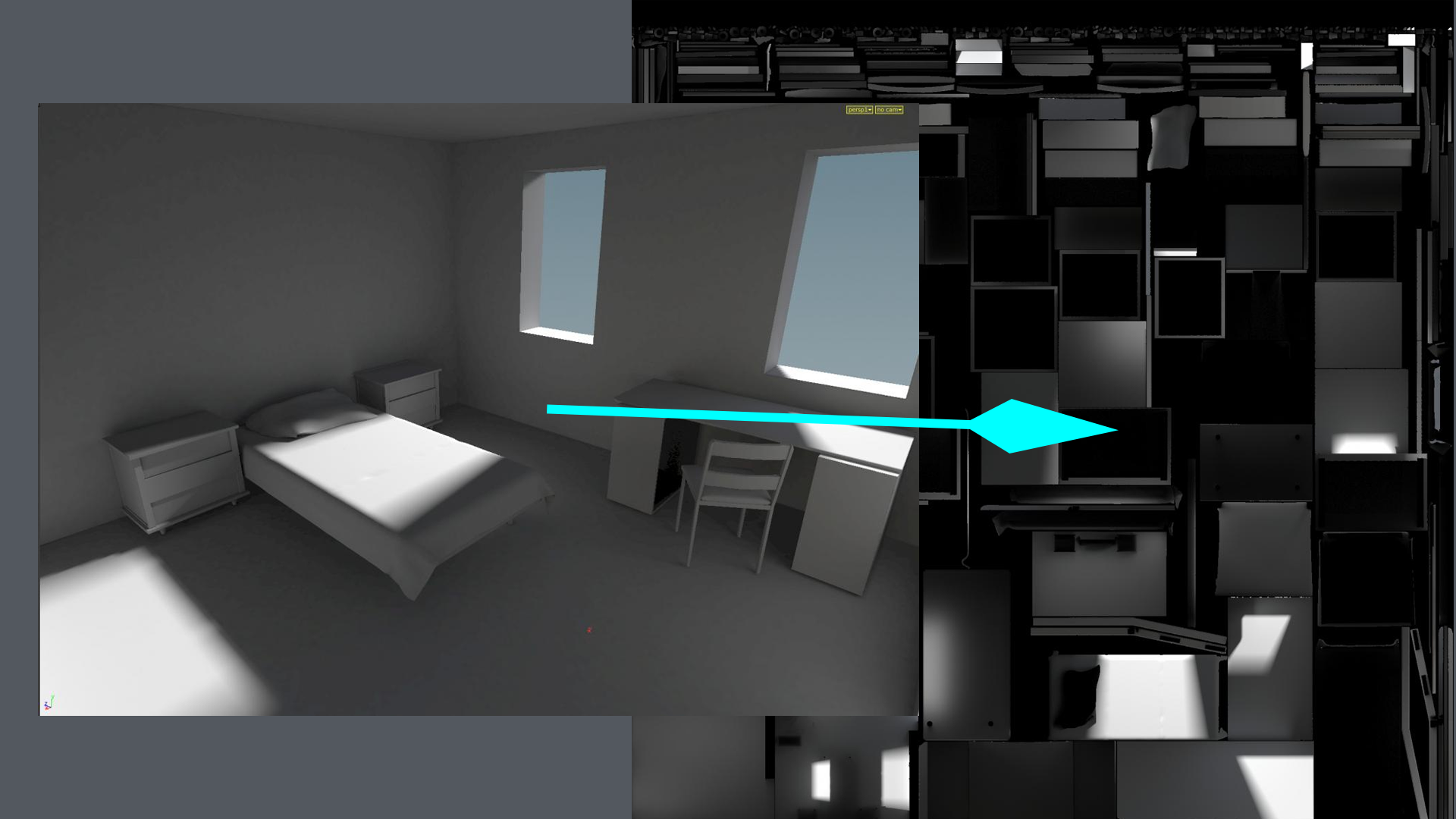
Creating a texture atlas can be done in several ways. I am showing two methods in the image above. The first method (left on the image) creates N^2 cameras around the subject, and renders out 1 image per camera. If we were to have 25 cameras in total, we would also get 25 images as output. But since our texture atlas needs to be a single image, you would need to stitch them together into a single texture. This is where method 2 comes in for the win: Lens Shaders. With the lens shader we can basically remap where every single ray for our pixel is originating from, hence allowing us to “cut up” the lens and move it to where those cameras would be located. This means we can quite literally change settings on what kind of output we need in realtime. Which can be seen in the gif below.
The above is the output texture. Note that for textures in games it is recommended to use 1:1 aspect ratio with a power of two resolution.
{
######## Hemi-Octahedron ########
float xy_size = 6;
float camera_width = 0.2;
float camera_zoom = 10;
int nFrames = int(xy_size * xy_size);
float fx = fit(x, -1, 1, 0, 1) * float(xy_size);
float fy = (1 - fit(y, -1, 1, 1, 0)) * float(xy_size);
float floorx = clamp(float(xy_size) - trunc(fx) - 1.0, 0, xy_size-1);
float floory = clamp(float(xy_size) - trunc(fy) - 1.0, 0, xy_size-1);
float fracx = (frac(fx) * 2.0 - 1) * camera_width;
float fracy = (frac(fy) * 2.0 - 1) * camera_width;
vector ImpostorVector(vector2 Coord){
vector2 CoordModify = Coord;
CoordModify.x *= 2.0;
CoordModify.x -= 1.0;
CoordModify.y *= 2.0;
CoordModify.y -= 1.0;
vector ImpostorRenderVector;
vector2 HemiOct = set(CoordModify.x + CoordModify.y, CoordModify.x - CoordModify.y);
HemiOct.x *= 0.5;
HemiOct.y *= 0.5;
ImpostorRenderVector = set(HemiOct.x, HemiOct.y, 0);
ImpostorRenderVector.z = 1.0 - dot(abs(HemiOct), {1.0, 1.0});
return normalize(ImpostorRenderVector);
}
vector2 Input = set(float(int(floory)) / float(xy_size-1), float(int(floorx)) / float(xy_size-1));
vector P = swizzle(ImpostorVector(Input), 0, 2, 1);
vector N = normalize(P);
vector XDir = normalize(cross(set(0,1,0), N));
vector2 Coord = set(floorx, floory);
if (xy_size%2==1) {
if(Coord == set(ceil(float(xy_size-1)/2.0), ceil(float(xy_size-1)/2.0)))
XDir = set(-1,0,0);
}
vector YDir = normalize(cross(XDir, N));
P += ((XDir*fracx) + (YDir*-fracy));
P = (P * camera_zoom);
I = N;
}
Conclusion
We’ve gone through different topics in the text above... We now know what lens shaders are and how they work; Which together with some basics about CVEX and where to store it, should enable you to create Lens Shaders by yourself. In the examples above we went through some basic examples first, and ended with something a bit more complex: a Hemi-Octahedral Lens Shader to render an impostor atlas. In order to create more lens shaders we just need the math to be correct, and assign it to the correct export variables: P and I.
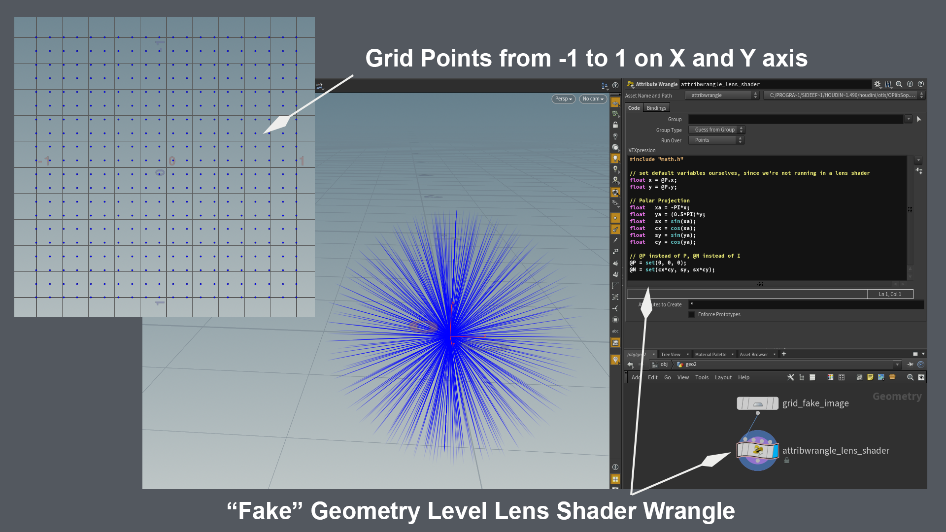
To debug lens shaders I really recommend building them in the geometry context as seen in the above image. It essentially uses a grid set to points together with a point wrangle. Just make sure you have the grid set to size 2, so that it its border points span across -1 to 1 in both X and Y axis. (mimicking the normalized pixel positions in the lens shader) A wrangle set to points will essentially let you use the same code as a lens shader, with the minor difference that you will need to initialize x and y yourself, and use different export variables. P in lens shader should become @P in the wrangle, while I in the lens shader will become @N in the wrangle. We’re using @P to set the world position of the points (ray origin), and @N to visualize I (ray direction). Have fun rendering!
CREATED BY

コメント
Santi Gutierrez 7年, 9ヶ月 前 |
This is awesome Paul. Thanks a lot for the hard work. Very interesting.
bonsak 7年, 9ヶ月 前 |
Wonderful write-up! Thanks,
Doca 7年, 9ヶ月 前 |
Very good explanation. Is there way to remap lens with some STmap, I mean to do the lens distortion based on external texture image?
Ambrosiussen 7年, 9ヶ月 前 |
Hey,
Yes that is possible. Check out the example that eetu posted here:
https://forums.odforce.net/topic/8471-eetus-lab/?page=9&tab=comments#comment-132784
He modifies P based on a texture. You could do the same with an stmap.
Paul
KyuIn 7年, 6ヶ月 前 |
Thanks for great explanation.
By the way, Could you help me with 'Creating a CVEX operator' part?
I'm using Houdini 17. It looks little different. the closest thing I found at Houdini 17's setup was
'Definition' - VEX
'Network Type '- CVEX VOP
it shows up at 'Material Network' And then it doesn't work as Lens shader.
Please tell me what i'm doing wrong and how to fix it. : )
jbartolozzi 7年, 1ヶ月 前 |
This is awesome.
Please log in to leave a comment.