| On this page |
|
Overview 
In traditional keyframe animation, realistic-looking motion for trajectories can be difficult and tedious to achieve. The animator would need to set multiple keyframes along an arc in an attempt to create a realistic trajectory, and changing any properties of the trajectory (for example, height or distance) would require the animator to update several poses and keyframes along the arc.
With the use of physics-based motion, animators can roughly key important poses, and the motion and spacing between poses are replaced with physics-based trajectory. This can significantly speed up and simplify the animation workflow when working with trajectories in your scene.
Houdini’s ![]() Projectile Motion and
Projectile Motion and ![]() Pendulum Motion SOPs are used to determine physics-based motion. These nodes take as input the character skeleton animation, and replaces sections of the animation with projectile/pendulum motion. These nodes change the character’s position, but not the character’s pose.
Pendulum Motion SOPs are used to determine physics-based motion. These nodes take as input the character skeleton animation, and replaces sections of the animation with projectile/pendulum motion. These nodes change the character’s position, but not the character’s pose.
Basic keyframe animation setup 
In a basic setup for keyframe animation, you start with a character animation rig, set keyframes on the rig, add the projectile/pendulum motion, and put the motion back onto the rig.
In this example, we have a simple keyframed animation of a character jumping.
-
Set up the node network:
-
Connect the character animation rig node (animated skeleton output) to the Projectile Motion SOP (1st input). Keyframes are set on the character animation rig for the jump motion.
-
Connect the Projectile Motion SOP (1st output) to another copy of the character animation rig node (animated skeleton input). This second character animation rig will have the animation with projectile motion.
-
-
On the Projectile Motion SOP, the Joint Group is set to the locomotion joint of the skeleton. The locomotion joint is the joint that defines the motion of the entire skeleton. It usually has a name like
C_COG.See How-to for more information on using specific joints to determine the projectile/pendulum motion path.
-
When the Projectile Motion SOP is first plugged into the network, the Projectile Sections multiparm is empty, so no projectile motion is added to the animation. To add projectile motion:
-
Click
 beside the Projectile Sections multiparm. This will add a tab of parameters for each new section of projectile motion.
 -
Turn on Create Projectile Motion.
-
Set Range to Replace with the range of frames in the original animation that you would like to replace with projectile motion.
Tip
Select the first character animation rig node to see the frames that are keyframed, and then use those frames in Range to Replace.
-
Adjust start/end positions and trajectory 
Adjust the start and end (target) positions, and trajectory of the projectile motion path using the handles in the Projectile Motion viewer state.
Note
Turn on Shift Animation After Projectile so that the animation after the projectile motion continues from the new end position.
If you make changes to the start or end position of the projectile motion but don’t turn on Shift Animation Before Projectile or Shift Animation After Projectile, the animation will pop.
You can also change the start and end positions in the parameter editor by setting the Start Position and Target Position values in the Positions section of the Projectile Motion SOP. Change the height of the arc by adjusting the Life parameter.
Add projectile motion between multiple keys 
In this example, we have an animation of a soccer ball being juggled. Keyframes are set for the different ball positions in the ball_positions HDA.
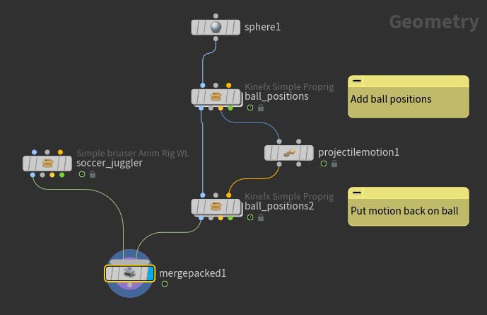
Turn on the display flag for ball_positions to see the original keyframed animation (soccer_juggler is templated in the below animation).
-
On the Projectile Motion SOP, set Joint Group to the joint at the center of the ball.
-
To quickly add projectile motion between multiple keyframes, use the Bake option on the Projectile Motion SOP:
Click the Bake button. In the Projectile Motion Baking window:
-
Bake To defaults to the current Projectile Motion SOP.
-
Set Bake From to the character animation rig with the keyed positions. In this example, it is
ball_positions. -
The Frame Start and Frame End values are filled in with the frame range of the animation by default.
-
Click Bake All.
-
In the Projectile Motion SOP, a section of projectile motion is created between each key in the Bake From node. Each projectile motion section has a tab of parameters in the Projectile Sections multiparm. To remove a section of projectile motion, click ![]() in the tab you want to remove.
in the tab you want to remove.
Note
Use the Bake option as an initial set up step. If you have already adjusted the parameters in the projectile motion sections, using Bake again will re-create all the projectile motion sections from the animation keyframes, and you will lose your changes.
The projectile motion output is wired back into the ball animation rig, ball_positions2. Turn on the display flag for ball_positions2 to see the updated animation with projectile motion.
Combine projectile and pendulum motion 
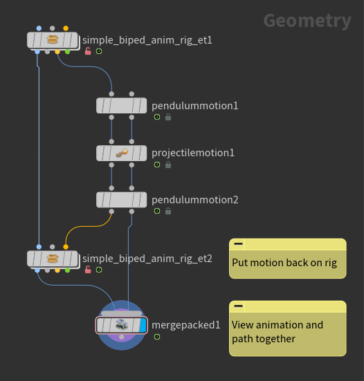
In this animation, keys are set on the character animation rig to create a swinging animation:
The following physics-based motion is added to the animation based on the approximate path of the original animation:
-
Frame 1-40: pendulum motion
-
Frame 40-50: projectile motion
-
Frame 50-100: pendulum motion
Note
When chaining together multiple Projectile Motion and Pendulum Motion SOPs, connect the two outputs of one SOP to the two inputs of the next SOP. When physics is added to an animation, the timeline of the original animation is compressed or extended during the period of projectile/pendulum motion. This is to ensure that the animation following the projectile/pendulum motion is the same as what it would be without projectile/pendulum motion. This time warping information is passed on through the Motion Path inputs and outputs so that the Projectile Motion and Pendulum Motion SOPs downstream can define their Range to Replace parameters based on the timeline of the original animation.
Add projectile and pendulum motion 
Frame 1-40: Pendulum Motion 
-
On the first Pendulum Motion SOP, click
beside the Pendulum Sections multiparm. This will add a tab of parameters for the new section of pendulum motion. -
Turn on Create Pendulum Motion.
-
Set Range to Replace to
1and40. -
Once you add a pendulum motion section, the pendulum pivot position will default to the origin. Change the pivot position in the Pendulum Motion viewer state, or adjust the Pivot parameters.
Move pivot in Pendulum Motion viewer state -
Turn on End at Target so that once the character reaches the end of the pendulum swing, it will not continue its swing backward.
Frame 40-50: Projectile Motion 
-
On the Projectile Motion SOP, click
beside the Projectile Sections multiparm. This will add a tab of parameters for the new section of projectile motion. -
Turn on Create Projectile Motion.
-
Set Range to Replace to
40and50. -
Change the height of the arc in the Projectile Motion viewer state, or adjust the Life parameter.
Adjust height of arc in Projectile Motion viewer state
Frame 50-100: Pendulum Motion 
-
On the second Pendulum Motion SOP, click
beside Pendulum Sections to add a new section of pendulum motion. -
Turn on Create Pendulum Motion.
-
Set Range to Replace to
50and100. -
Change the pivot position.
-
Turn on End at Target so that once the character reaches the end of the pendulum swing, it will not continue its swing backward.
-
Set Post Behavior to Hold so that once the character reaches the end of the pendulum swing, it will stay at that position instead of popping back to the end position of the original animation.
After tweaking the pendulum pivot positions and projectile motion height, we have the below animation:
Adjust hand positions 
If you want to change the position of the hands during the pendulum swings so that they always point toward the pivot:
-
In the Pendulum Motion SOP, click
 beside Pivot Group.
 -
Select all the hand and finger joints in the viewport or Rig Tree window, and click Accept.
Smooth out transitions 
The animation has a rough transition between the projectile motion and the second pendulum motion.
To smooth out the transition:
-
In the Transitions section of the second Pendulum Motion SOP, turn on Transition In.
-
The Transition In values are the number of frames that are removed before and after the start of the pendulum motion to create a smooth transition region. Adjust the Transition In values until you get a smooth transition.
Adjust speed 
Increase the inital speed of the pendulum upswing by increasing the Speed parameter in the first Pendulum Motion SOP. This will increase the speed in the upward direction (opposite gravity). To launch the character forward instead, turn on Reverse Direction.
With the increased initial speed of the animation, the character looks like it is floating and slowing down through the beginning of the second pendulum motion. To maintain the faster speed through the second pendulum motion, turn on Maintain Input Speed on the second Pendulum Motion SOP. Turn on Reverse Direction as well, so that the increased speed is in the downward swing direction.
Physics-based motion with motion retargeting 
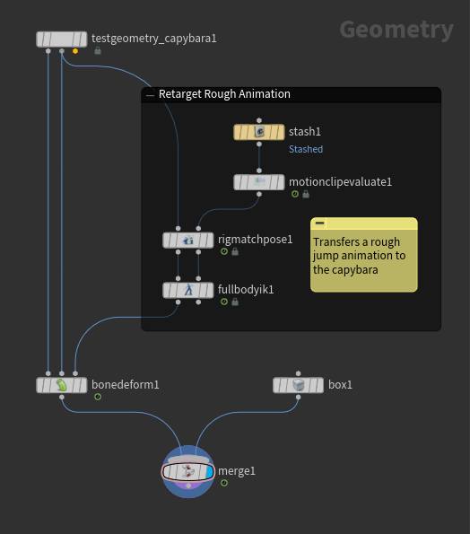
In this example, we add physics-based motion to a motion retargeting workflow. We start with a rough jump animation that is transferred onto a capybara geometry.
The rough jump animation is stored in a ![]() Stash SOP as a motion clip. The motion from the
Stash SOP as a motion clip. The motion from the ![]() Full Body IK SOP is then transferred onto the capybara.
Full Body IK SOP is then transferred onto the capybara.
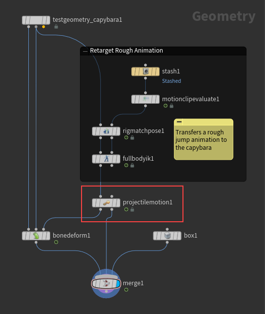
Add physics-based motion by connecting the Projectile Motion SOP between the Full Body IK SOP and the ![]() Bone Deform SOP. Optionally connect the 2nd output of the Projectile Motion SOP to the
Bone Deform SOP. Optionally connect the 2nd output of the Projectile Motion SOP to the ![]() Merge SOP to see the path of the projectile motion in the final output.
Merge SOP to see the path of the projectile motion in the final output.
On the Projectile Motion SOP:
-
Click
beside the Projectile Sections multiparm to add a new section of projectile motion. -
Turn on Create Projectile Motion.
-
Set Range to Replace to the frame range in the original animation to replace with projectile motion.
-
Adjust the Start Position as necessary. Turn on Shift Animation Before Projectile so that the animation before the section of projectile motion transitions smoothly into the projectile motion.
-
Adjust the Target Position as necessary. Turn on Shift Animation After Projectile so that the projectile motion transitions smoothly into the remaining animation.
Network management 
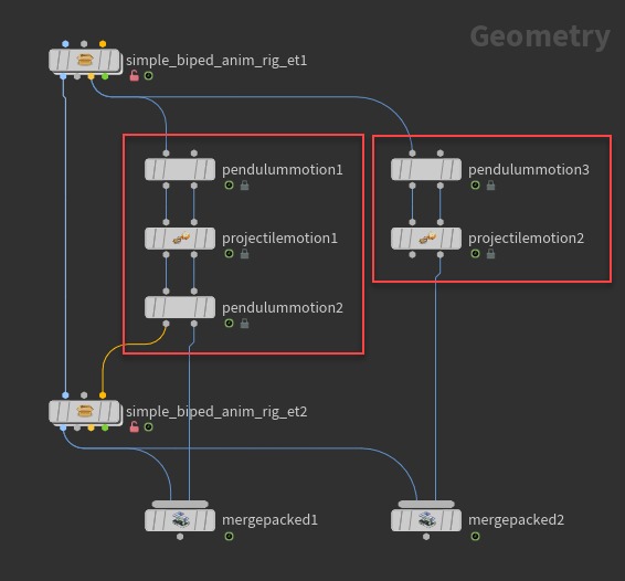
Multiple projectile and pendulum motion sections can either be put into one Projectile Motion or Pendulum Motion SOP, or the different sections can be kept in their own separate node.
In the node network below, the Projectile Motion and Pendulum Motion SOPs on the left each contain one section of projectile/pendulum motion. In pendulummotion3 on the right, there are 2 sections of pendulum motion, with the Range to Replace parameters set to those in pendulummotion1 and pendulummotion2.
Node Arrangement |
Benefit |
|---|---|
Combine different projectile/pendulum motion sections into one Projectile/Pendulum Motion SOP |
Fewer nodes to manage. |
Separate node for each projectile/pendulum motion section |
You can easily adjust the entire animation by changing the first projectile/pendulum motion, and turning on Maintain Input Speed for each subsequent node. This propagates the change in the first Projectile/Pendulum Motion SOP down the rest of the chain of nodes. |
How-to 
| To... | Do this |
|---|---|
|
Replace a section of animation with projectile/pendulum motion |
Set Range to Replace with the range of frames in the original animation that you would like to replace with projectile/pendulum motion. |
|
Create projectile/pendulum motion for an animation with multiple keyframes |
Use the Bake button to create a default setup of projectile/pendulum motion paths between each key.
In the Projectile/Pendulum Motion SOP, a section of projectile/pendulum motion will be created between each key in the Bake From node. Each new projectile/pendulum motion section will have a tab of parameters in the Projectile/Pendulum Sections multiparm. Note The Bake Current Section option creates projectile/pendulum motion for the section of animation you are currently at. For example, if you are at frame 18, and the animation has keys at frames 10 and 20, then Bake Current Section will create a projectile/pendulum motion section between frames 10 and 20. |
|
Use a custom frame range from the input animation motion path |
These parameters are only available if nothing is connected to the Motion Path (2nd) input. |
|
Use specific joints to determine the projectile/pendulum motion path |
Specify the joints you want to contribute to the skeleton’s center of mass in Joint Group:
All the joints in Joint Group contribute equally to the skeleton’s center of mass. The center of mass determines the projectile/pendulum motion path. Note Only the joints specified in Joint Group and their children move along the projectile/pendulum motion path. Because the locomotion joint is the parent joint that moves with the entire skeleton, it should always be one of the joints included in Joint Group. If a child joint is specified in Joint Group, but not the locomotion joint, the child joint would move along the projectile/pendulum motion path, while the locomotion joint follows the motion path of the original animation. Note Many skeletons have a root joint that remains at a single position (usually the origin). This root joint usually does not move with the rest of the skeleton (as opposed to the locomotion joint), and so you generally would not want it to contribute to the skeleton’s center of mass. If no joints are specified in Joint Group, every joint in the skeleton contributes to the center of mass, including the root joint, which is usually undesirable. Therefore, it is good practice to explicitly specify all the joints you want to contribute to the center of mass instead of leaving Joint Group empty. If you want some joints to contribute more to the skeleton’s center of mass:
The Configure Joints SOP creates a center of mass joint based on the joints in the Configurations multiparm. The Projectile/Pendulum Motion SOP uses this center of mass joint to determine the projectile/pendulum motion path. |
|
Change the start and end positions of the projectile/pendulum motion |
In the Projectile/Pendulum Motion viewer state, select the box at the start or end of the projectile/pendulum motion path, and adjust the position using the handles. or In the Positions section, turn on Start Position and Target Position, and adjust the values. |
|
Smooth the transition into and out of the projectile/pendulum motion |
To smooth out the beginning of the projectile/pendulum motion:
To smooth out the end of the projectile/pendulum motion:
If your animation is popping because you changed the start or end position of the projectile/pendulum motion:
|
|
Maintain the speed from the incoming motion path into the projectile/pendulum motion |
Turn on Maintain Input Speed. Note For projectile motion, if Maintain Input Speed is turned on, the speed of the incoming motion path will determine the height of the arc (the Life parameter will be automatically turned off). If the height of the arc is adjusted in the viewport, this will automatically turn on the Life parameter and turn off Maintain Input Speed. |
|
Change the active projectile/pendulum motion path shown in the viewer state |
In the viewer state toolbar, change the Projectile field to a different projectile/pendulum motion section (corresponds to the Projectile Sections number in the parameter editor), or scroll through the Projectile field using the value ladder. |
Projectile motion 
| To... | Do this |
|---|---|
|
Adjust the height of the projectile motion |
Note Select the height plane and press R to switch the transform handle to rotate mode. This allows you to rotate the plane so that the projectile motion path skims the plane instead of reaching a specific height. |
|
Add the effect of air resistance on the projectile motion path |
In the Physical Properties section, Mass and Drag work together. Drag is the air resistance that acts on the projectile motion path. With a higher Drag, the character slows down more as it gets further along on the motion path. A higher Mass reduces the effect of Drag on the projectile motion. |
|
Add a wind effect on the projectile motion path |
In the Physical Properties section, change the Gravity values. |
Pendulum motion 
| To... | Do this |
|---|---|
|
Stop the pendulum swing once the animation reaches the end of the swing (keep the animation from swinging backward) |
In the pendulum section, turn on End at Target. |
|
Change the starting speed of the pendulum swing |
In the pendulum section, change the Speed parameter. A positive Speed launches the character up (along the swing trajectory opposite gravity), and a negative Speed launches the character down (along the swing trajectory in the same direction as gravity). Note If the starting speed is too low to hit the target position, the speed will be increased to the minimum speed needed to reach the target. Tip Instead of using a negative value for speed, turn on Reverse Direction, which keeps the same speed, but launches the character in the opposite direction. |
|
Tilt the plane of the pendulum swing to a non-vertical orientation |
Adjust the Tilt parameter. |