| On this page |
|

Overview 
The behavior of a rig can be built up by manually creating a graph or by piecing together rig components. Rig components are either pre-built components shipped with Houdini, or you can create your own components to be reused in different rigs. The ![]() APEX Autorig Component SOP is an interface to several pre-built rig components that add functionality such as FK, IK, and bone deform to build up the rig logic of a character.
APEX Autorig Component SOP is an interface to several pre-built rig components that add functionality such as FK, IK, and bone deform to build up the rig logic of a character.
We start by introducing Houdini’s pre-built rig components through several simple examples. We then use the rig components to build a basic rig for the ![]() Electra test geometry. Finally, different approaches are presented for building character rigs.
Electra test geometry. Finally, different approaches are presented for building character rigs.
Pre-built rig components 
This section presents several basic examples of the pre-built rig components available in the APEX Autorig Component SOP. We start with adding FK, bone deform, and control shapes to a 3-joint tube geometry. We then introduce the IK, spine, and transform driver rig components.
FK 
In this example, FK rig logic is added to a 3-joint tube geometry using the APEX Autorig Component SOP.
-
Start by drawing a skeleton for the tube geometry. The skeleton has joints
point_0,point_1, andpoint_2, wherepoint_0is the parent ofpoint_1, which is the parent ofpoint_2. See working with skeletons for more information on creating skeletons.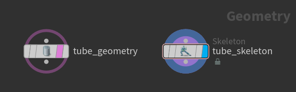
Create skeleton for tube geometry Draw a skeleton In this example, bone deformation is not added to the rig logic, so from this point onward, the tube geometry is no longer needed.
-
Add the skeleton to a packed folder structure which holds the different input elements (geometry, skeleton, and rig) for our tube “character”. Only elements that are added to a packed folder structure can be displayed in the animate state. See the packed character format for more information on how to prepare character data for evaluation in the animate state.
Note
The term “character” within the packed folder structure refers to a generic container that contains a piece of rig logic and the elements referenced by the rig logic’s inputs. In practice, a character container could be a character, a prop, or an asset.
-
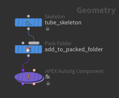
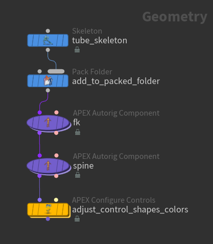
Create a rig graph using an APEX Autorig Component SOP. An easy way to start building up rig logic is by using the FK rig component, which creates an FK hierarchy based on the joint hierarchy of a skeleton.
Add FK rig logic to tube
Node |
Description |
||||||||
|---|---|---|---|---|---|---|---|---|---|
|
Adds character elements to a packed folder structure. In this example, the tube skeleton is added to the packed folder structure and named See the contents of the packed folder structure in the rig tree view:
The following packed folder hierarchy is displayed: / -- tube.skel A rig graph can now be added to the packed folder structure using the |
||||||||
|
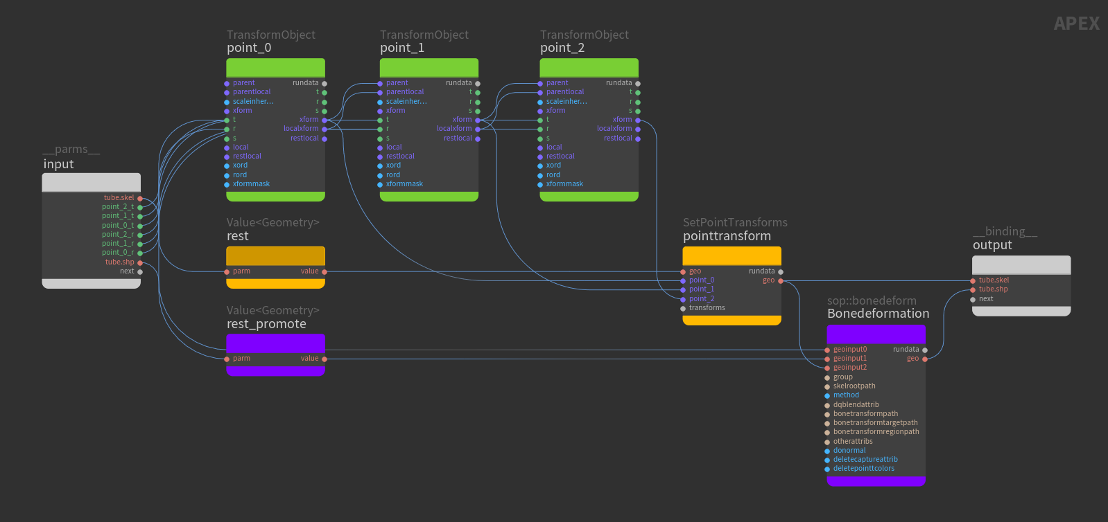
This pre-built FK rig component creates a rig graph by translating the tube skeleton in the packed folder structure into a rig hierarchy. It takes each of the skeleton joints and creates a TransformObject node that represents the skeleton joint position, with its restlocal parameter set to the rest position of the joint. The TransformObject nodes can then be turned into controls that the user can interact with in the animate state. The FK component adds the rig graph to the packed folder structure. In the APEX Autorig Component SOP, set the Component parameter to fktransform. Note The FK component translates the skeleton into a rig hierarchy, so it is useful to have this as the first pre-built component when building up rig logic.
The packed folder structure now contains the skeleton and the rig graph. Select the / -- tube.skel -- Base.rig Open the APEX network view to see the rig graph generated by the FK rig component, as shown below (nodes are rearranged and colors are added for clarity). The green TransformObject nodes represent the skeleton joints and are connected according to the skeleton joint hierarchy. The translate and rotate of each TransformObject node are promoted (their 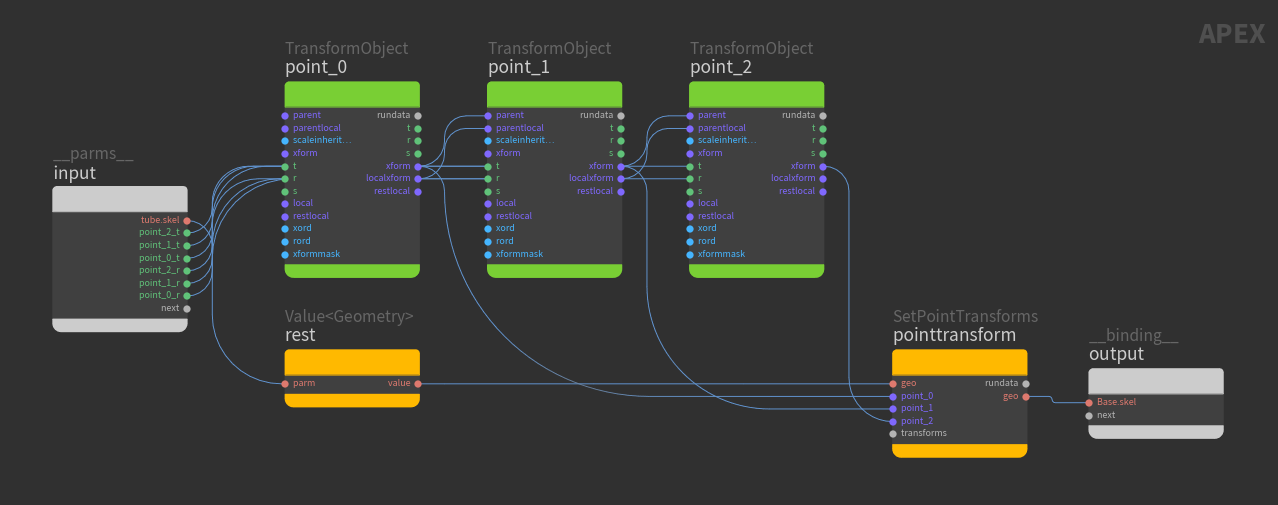
See geometry deformation for more information on the TransformObject and SetPointTransforms nodes. View the FK functionality in the animate state:
|
Bone deform 
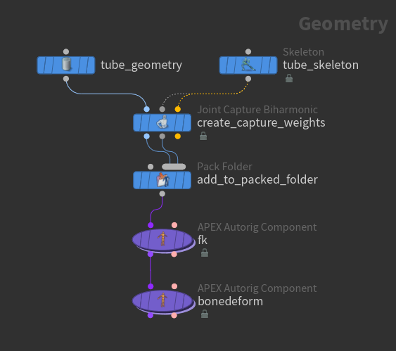
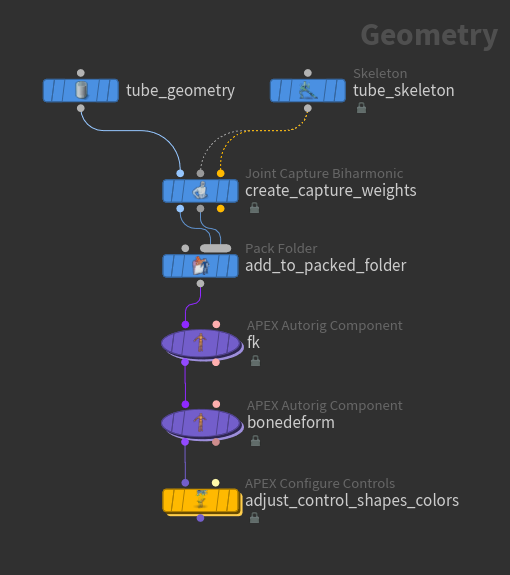
Bone deform rig logic is now added to the previous FK rig. To perform bone deformation, first create capture weights on the geometry using the ![]() Joint Capture Biharmonic SOP. The updated geometry is then added to the packed folder structure along with the skeleton.
Joint Capture Biharmonic SOP. The updated geometry is then added to the packed folder structure along with the skeleton.
Note
In other DCCs, weight creation often happens on the deformer. In Houdini, weight creation is separate from deformation. In this way, we can prepare the input geometry with the correct weights before diving into APEX to create the rig logic.
Node |
Description |
||||||||
|---|---|---|---|---|---|---|---|---|---|
|
Adds the following character elements to a packed folder structure:
Note The order of the inputs to the Pack Folder SOP must match the order that the Name and Type parameters are listed in the Pack Folder SOP parameters. See the packed character format for more information on naming character elements in the packed character format. The following packed folder hierarchy is displayed in the rig tree view: / -- tube.skel -- tube.shp |
||||||||
|
Adds bone deformation logic to the rig graph created by the FK component upstream. In the APEX Autorig Component SOP, set the Component parameter to bonedeform.
The bone deform rig component adds additional logic to the FK rig graph from the previous example.
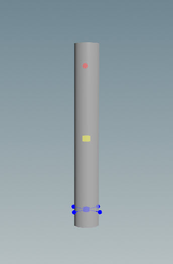
In the animate state, the tube geometry has controls that can be selected to perform FK posing. |
Configure controls 
Use the ![]() APEX Configure Controls SOP to configure the shapes and colors of the controls.
APEX Configure Controls SOP to configure the shapes and colors of the controls.
Node |
Description |
||||||||
|---|---|---|---|---|---|---|---|---|---|
|
Add configurations for different groups of controls by clicking
|
IK 
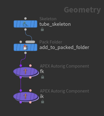
In this example, an IK rig is built for the tube skeleton. An FK rig hierarchy is first created from the skeleton, and then IK functionality is added on top of the FK rig.
Node |
Description |
||||||||||
|---|---|---|---|---|---|---|---|---|---|---|---|
|
Adds the tube skeleton to the packed folder structure. We name the skeleton |
||||||||||
|
Translates the tube skeleton into a rig hierarchy. In the APEX Autorig Component SOP, set the Component parameter to fktransform.
|
||||||||||
|
Adds IK logic to the rig graph created by the FK component upstream. In the APEX Autorig Component SOP, set the Component parameter to smoothik.
IK functionality in the animate state: |
Spine 
The spine autorig component adds a basic spine setup based on a spline curve. It can be used as a starting point for a bendy or twist setup. In this example, spine rig logic is added to the tube skeleton.
Node |
Description |
||||||
|---|---|---|---|---|---|---|---|
|
We create a 9-joint skeleton to better see the effects of the spine rig. 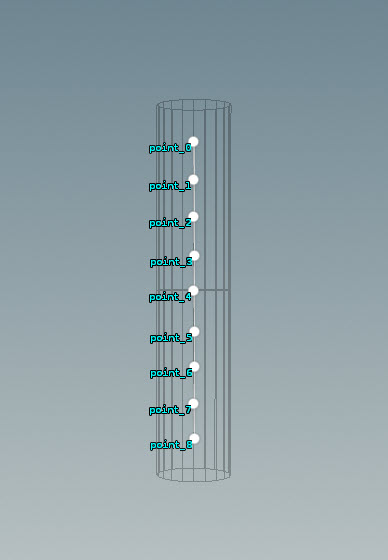
|
||||||
|
Adds the tube skeleton to the packed folder structure. We name the skeleton |
||||||
|
Translates the tube skeleton into a rig hierarchy. In the APEX Autorig Component SOP, set the Component parameter to fktransform.
|
||||||
|
Adds spline rig logic to the rig graph created by the FK component upstream. In the APEX Autorig Component SOP, set the Component parameter to spine.
|
||||||
|
Configures the shapes and colors of the joints and controls. Select this SOP and enter the animate state to view the spine functionality. The skeleton joints are red, and the spine controls are blue: |
Transform driver 
The transform driver rig component is used to create new controls that drive the transforms (translate, rotate, and scale) of existing controls in the skeleton. The existing controls are essentially constrained to the new controls. The new transform driver controls allow you to define different pivots and orientations for the existing skeleton joints without having to create new skeleton controls that would otherwise affect any bone deformation downstream.
In an APEX graph, the transform driver rig component creates new TransformObject nodes and adds a constraint between the new nodes and the existing TransformObject nodes that are being driven. The new nodes are not added to the skeleton. They are just extra controls used to drive the skeleton joints.
Node |
Description |
||||||||||||
|---|---|---|---|---|---|---|---|---|---|---|---|---|---|
|
We start with a 3-joint skeleton. |
||||||||||||
|
Adds new controls that drive existing controls on the skeleton. In the APEX Autorig Component SOP, set the Component parameter to transformdriver. In this example, we add a transform driver control,
Add a 2nd transform driver control We now add a 2nd transform driver control, Transform driver drives a joint at a different position When a transform driver control sits at a different position from the joint it is driving, the transform driver acts like a parent constraint. When the transform driver is rotated, the driven TransformObject and all of its children rotate about the transform driver. Transform driver sits at point_0 and drives point_1 Transform driver sits at point_0 and drives point_2 Transform driver sits at point_2 and drives point_1 |
Build a character rig 
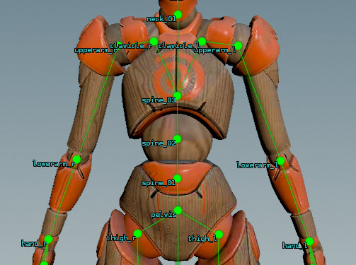
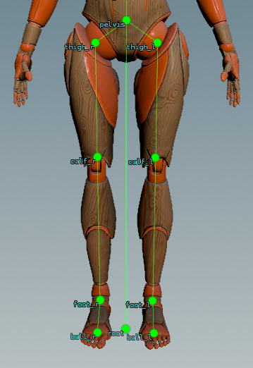
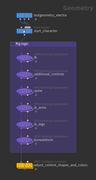
In this example, pre-built rig components are used to build a rig for the ![]() Electra test geometry. The following pieces are added to build the final rig:
Electra test geometry. The following pieces are added to build the final rig:
-
FK rig hierarchy based on the Electra skeleton joint hierarchy
-
IK logic
-
Additional controls
-
Spine logic
-
Configure controls
Create an FK rig 
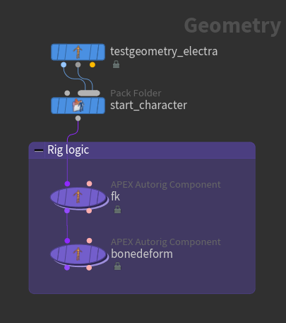
An FK rig is created for the Electra test geometry, and bone deform logic is added to the rig graph in order to view the FK functionality on the character.
Node |
Description |
||||||
|---|---|---|---|---|---|---|---|
|
On the Electra test geometry, set the Output parameter to Skin Surface. This outputs Electra’s shape as its 1st output. The 2nd output is Electra’s skeleton. |
|||||||
|
Adds the following character elements from the Electra test geometry to a packed folder structure:
At this point, the Electra skin and skeleton are added to a packed folder structure. The following packed folder hierarchy is displayed in the rig tree view: / -- Base.shp -- Base.skel |
||||||
|
Creates a rig graph by translating the Electra skeleton into a rig hierarchy. The rig graph is added to the packed folder structure. In the APEX Autorig Component SOP, set the Component parameter to fktransform.
The following packed folder hierarchy is now displayed in the rig tree view: / -- Base.shp -- Base.skel -- Base.rig |
||||||
|
Adds bone deformation logic to the rig graph. In the APEX Autorig Component SOP, set the Component parameter to bonedeform. The default values in the restgeo, restskeleton, and outputgeo parameters match the names of the character elements in the packed folder structure. Perform FK posing on Electra in the animate state:
|
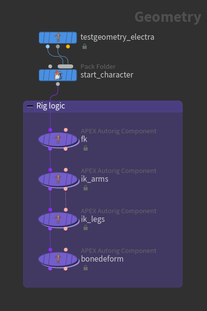
Add IK rig logic 
We build on the above FK rig logic by adding IK functionality for the arms and legs. The IK rig component defines the functionality for a single IK chain (and optionally its mirrored joints), so an IK component is needed for the arms and another for the legs.
Node |
Description |
||||||||||
|---|---|---|---|---|---|---|---|---|---|---|---|
|
Adds IK functionality to the character’s arms. In the APEX Autorig Component SOP, set the Component parameter to smoothik.
|
||||||||||
|
Adds IK functionality to the character’s legs. In the APEX Autorig Component SOP, set the Component parameter to Use Second Input, which copies the settings from the previous APEX Autorig Component SOP to the current SOP. You can then turn on various parameters to override the previous component’s settings.
|
||||||||||
|
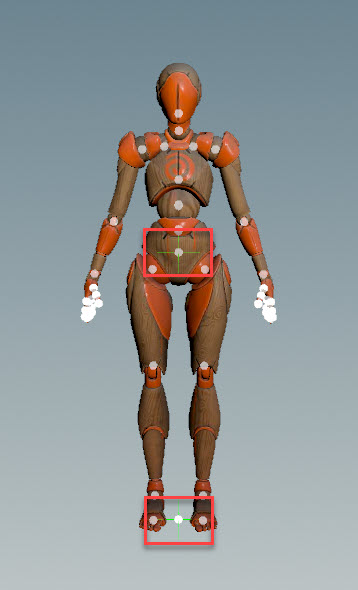
View the IK behavior on Electra:
|
Add spine rig logic 
We now add spine logic to the Electra rig. Before adding the spine rig component, we add a hierarchy of additional controls to the rig, where one of the controls is used by the spine component as a spine control.
Node |
Description |
||||||||||||||
|---|---|---|---|---|---|---|---|---|---|---|---|---|---|---|---|
|
Adds two controls to the rig - a In the APEX Autorig Component SOP, set the Component parameter to transformdriver. Click
|
||||||||||||||
|
Adds spline logic to the rig. In the APEX Autorig Component SOP, set the Component parameter to spine.
The video below shows the difference between a rig with and without spline logic. The skeleton spine joints are yellow, and the spine controls in the spline logic (right video) are green. |
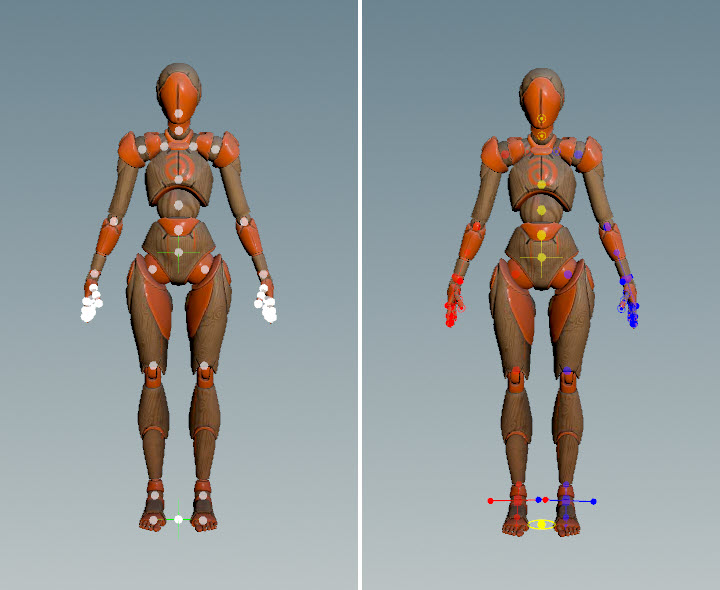
Configure controls 
Use the ![]() APEX Configure Controls SOP to configure the shapes and colors of the controls. Specify the rig to configure the controls for in the Rig Source parameter. In our example, we set Rig Source to
APEX Configure Controls SOP to configure the shapes and colors of the controls. Specify the rig to configure the controls for in the Rig Source parameter. In our example, we set Rig Source to Base.rig.
After configuring the controls, we are finished building the rig for Electra.
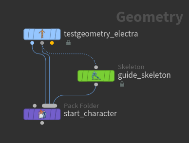
Using a guide skeleton to create a rig hierarchy 
In this example, joints are added to a base skeleton to create a guide skeleton. The guide skeleton is used to create an initial rig hierarchy, and rig logic pieces are added to the hierarchy to build the final rig. The added joints are used later as a reference for creating controls - essentially, they are controls represented as joints. For this reason, you would need to know beforehand the controls you would like in your rig so that the appropriate joints are added to the base skeleton. Because the controls are represented as joints, we can define the hierarchy and rest positions of the controls as part of the guide skeleton.
The steps to building the rig:
-
Add joints to the base skeleton to create a guide skeleton.
-
Create an FK hierarchy rig graph from the guide skeleton using the FK rig component. After this point, the guide skeleton is no longer used. All the information that is needed to build the rig will come from the rig graph.
-
Add rig logic pieces (IK, bone deform, etc.) to build the final rig.
Create a character 
We start with the ![]() Electra test geometry and use its skeleton as the base skeleton. Joints are then added to the base skeleton to create a guide skeleton. The Electra skin, base skeleton, and guide skeleton are then added to a packed folder structure.
Electra test geometry and use its skeleton as the base skeleton. Joints are then added to the base skeleton to create a guide skeleton. The Electra skin, base skeleton, and guide skeleton are then added to a packed folder structure.
Node |
Note |
|---|---|
|
On the Electra test geometry, set the Output parameter to Skin Surface. This outputs Electra’s shape as its 1st output. The 2nd output is Electra’s skeleton, which is used as the base skeleton. |
|
|
The 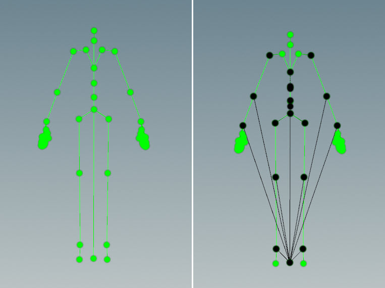
|
|
Adds the following character elements to a packed folder structure:
|
Build the rig logic 
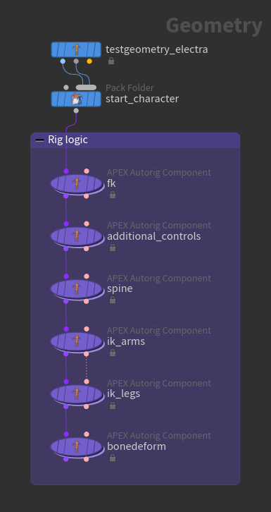
Several pre-built rig components are used to build up the rig logic of the character. Each of the ![]() APEX Autorig Component SOPs below adds a piece of rig logic to the overall rig logic of the character.
APEX Autorig Component SOPs below adds a piece of rig logic to the overall rig logic of the character.
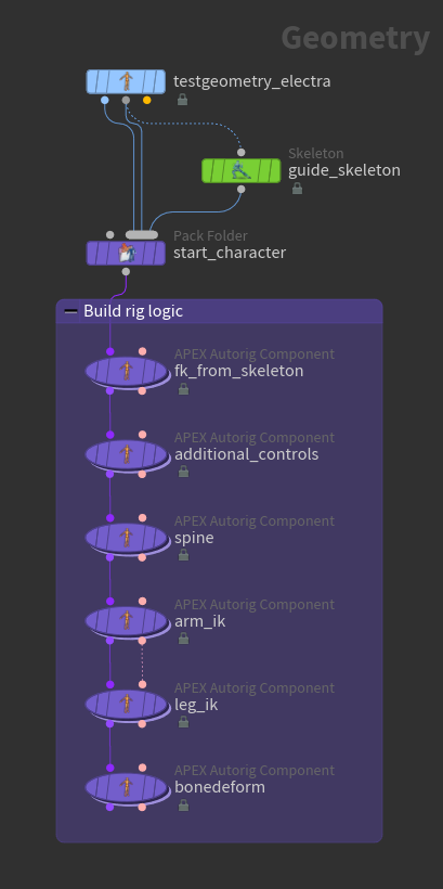
For more information on the individual rig components, see pre-built rig components. The table below highlights the settings specific to building a rig with a guide skeleton.
Node |
Rig component |
Note |
|---|---|---|
|
fktransform |
Creates a rig graph by translating the guide skeleton in the packed folder structure into a rig hierarchy. After this point, the guide skeleton is no longer used. All the information needed to build the rig will come from the rig graph created by this FK component. In the Source tab, set the skeleton parameter to |
|
transformdriver |
Turn off the guidesource parameter because information is being retrieved from the rig graph and not the guide skeleton. |
|
spine |
Turn off the guidesource parameter. |
|
smoothik |
Turn off the guidesource parameter. |
|
Use Second Input |
Turn off the guidesource parameter. |
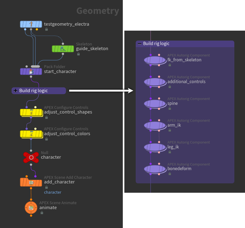
Add the character to a scene 
Use the ![]() APEX Scene Add Character SOP and
APEX Scene Add Character SOP and ![]() APEX Scene Animate SOP to add the character to a scene to be animated. See the animation workflow for more information.
APEX Scene Animate SOP to add the character to a scene to be animated. See the animation workflow for more information.
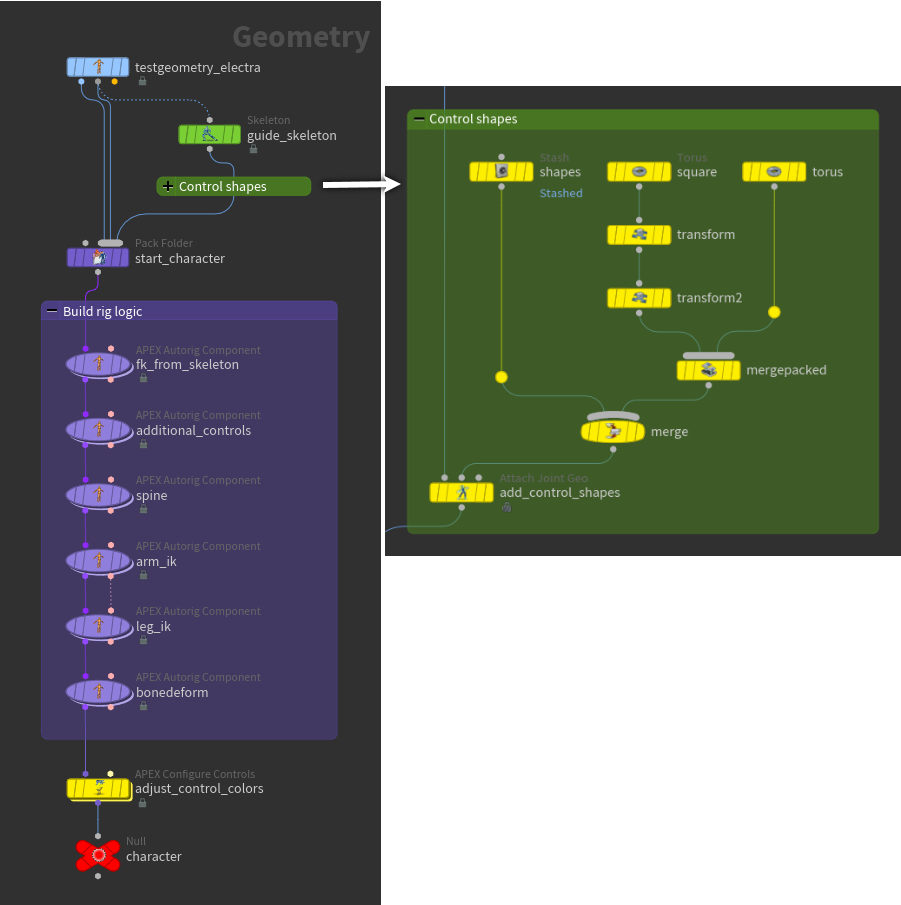
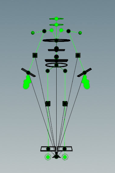
Using a guide skeleton with added control shapes 
In this example, joints are added to a base skeleton to create a guide skeleton. Control shapes are then added to the guide skeleton, and this final guide skeleton is added to a packed folder structure.
When building the rig logic further down, information on the control positions and shapes is retrieved from the guide skeleton, which is faster than retrieving information from the rig graph.
Node |
Rig component |
Note |
|---|---|---|
|
fktransform |
Creates a rig graph by translating the base Electra skeleton into a rig hierarchy. In the Source tab, set the skeleton parameter to |
|
transformdriver |
Adds additional controls to the rig and checks the guide skeleton to get the correct positions. Set the guidesource parameter to |
|
spine |
Turn off the guidesource parameter. |
|
smoothik |
Turn off the guidesource parameter. |
|
Use Second Input |
Turn off the guidesource parameter. |
|
N/A |
Set the Guide Source parameter to |