Primary Axis
Axis that points toward the child.
| On this page |
|
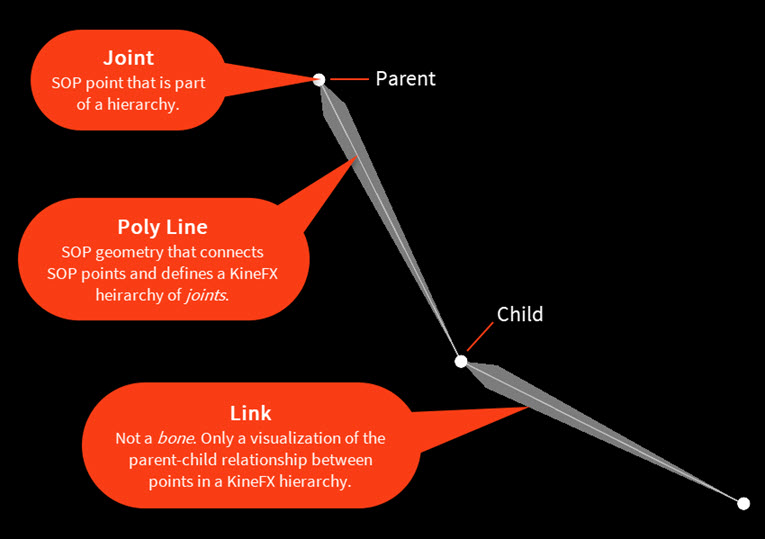
In KineFX, everything is a SOP point. The world transform of a point is defined by a position and a 3×3 transform matrix (translation, rotation, scale). A point becomes a joint when it has a transform attribute and a name attribute.
A KineFX hierarchy or skeleton is represented as a collection of points connected by polygon lines. The parent-child relationship between the joints in a hierarchy is determined by vertex order. When traversing the hierarchy, however, point ordering is not considered.
You can create skeletons from scratch, bring them in from the object-level, or import them from other DCC packages.
KineFX is a joint-based system, unlike the bone-based object-level rigging tools. There are key differences between object-level bones and geometry-level joints:
Bones have length, whereas joints only consider their local space translations to offset themselves from their parents.
Bones have a fixed orientation, so its child is always offset in -Z by the length of its parent.
Bones do not support scale compensation, making squash and stretch animation pipelines unwieldy, impacting performance.
Deformation of a capture (skin) is not driven by the bone itself; it is driven instead by the ![]() Capture Region SOP inside the bone object. The difference between the Capture Region SOP’s capture pose and the current pose drives the object-level skin’s deformation.
Capture Region SOP inside the bone object. The difference between the Capture Region SOP’s capture pose and the current pose drives the object-level skin’s deformation.
Object-level capture poses are attached to their skins, so the skin will break if you start deleting parts of the skeleton. On the other hand, the capture poses of SOP skeletons are an input to the ![]() Joint Deform SOP, so you can alter a SOP capture pose without having to re-capture (re-skin) its geometry. For example, you can make changes to a skeleton’s joint orientations or tweak a character’s pivots and not affect its skin.
Joint Deform SOP, so you can alter a SOP capture pose without having to re-capture (re-skin) its geometry. For example, you can make changes to a skeleton’s joint orientations or tweak a character’s pivots and not affect its skin.
You can create a skeleton from scratch by drawing its joints using the ![]() Skeleton SOP:
Skeleton SOP:
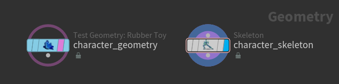
In the network view at the geometry (SOP) level, put down a Skeleton SOP, select it, and turn on its display flag.
Put down your character’s geometry node and turn on its template flag. You can now see your character’s geometry in the viewport when drawing its skeleton:
Tip
You can change how your templated geometry is displayed in the viewport. From the Display Options window (press D when hovering over the viewport), set Set display options for to Template Model Geometry, and choose one of the options in the Draw drop-down menu. We recommend using either Smooth Shaded or Smooth Wire Shaded.
Select the Skeleton SOP.
Click ![]() on the left toolbar, or hover over the viewport and press Enter. You are now in the Skeleton viewer state, where you have access to the Skeleton toolbar above the viewport, the
on the left toolbar, or hover over the viewport and press Enter. You are now in the Skeleton viewer state, where you have access to the Skeleton toolbar above the viewport, the ![]() menu options, and the skeleton state hotkeys.
menu options, and the skeleton state hotkeys.
On the Skeleton toolbar, set Mode to Create.
Tip
F toggles the Mode between Create and Modify. See the skeleton hotkeys for more keyboard shortcuts.
In the Joint Placement drop-down menu, select View Based, which places joints at the mid-point of the geometry. See joint placement for more options.
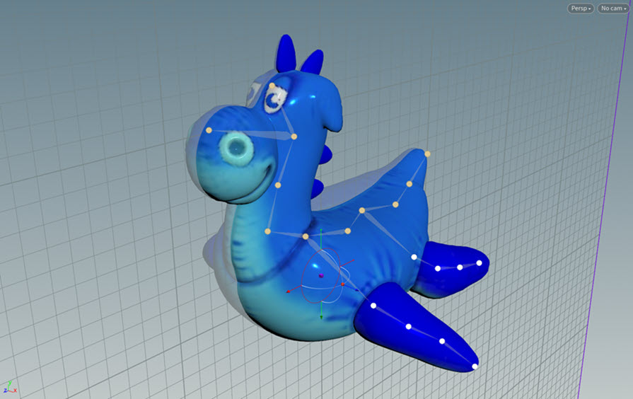
Draw the skeleton:
To modify the skeleton, turn on Tweak Mode on the Skeleton toolbar. If Child Compensate is off, dragging a joint moves the joint and its descendants. If Child Compensate is on, dragging a joint only moves the joint and not its descendants:
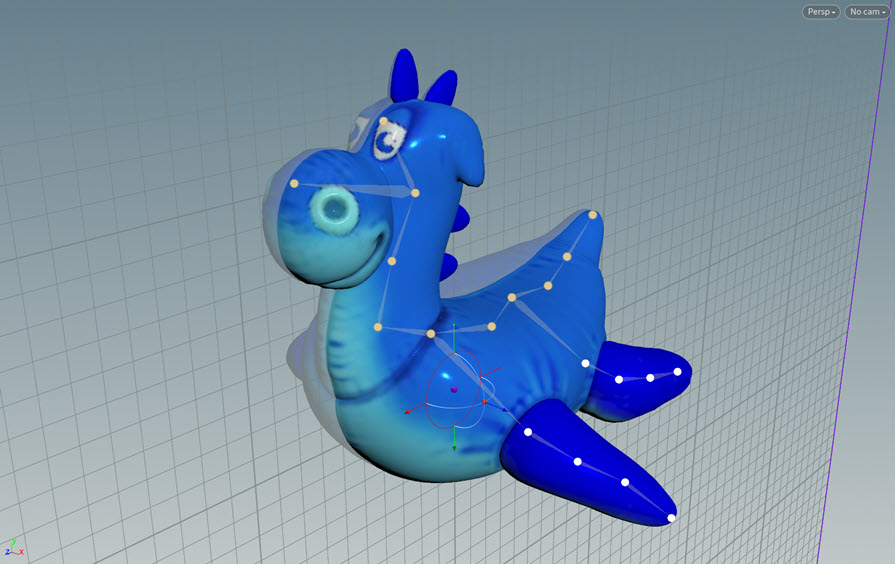
Line up the joints in the middle of the skeleton:
Display the construction plane in the viewport by clicking ![]() on the right toolbar.
on the right toolbar.
![]() click
click ![]() and turn on Construction Plane Handle.
and turn on Construction Plane Handle.
![]() click the construction plane handle and select Align normal with world X axis. This orients the construction plane so that its normal points along the X-axis:
click the construction plane handle and select Align normal with world X axis. This orients the construction plane so that its normal points along the X-axis:

Select the joints down the middle of the skeleton.
![]() click in the viewport and select Snap Selection to Construction Plane
click in the viewport and select Snap Selection to Construction Plane
Rename the joints:
In the Skeleton viewer state, select a point.
On the Skeleton toolbar, rename the point in the Name field.
To see the joint names in the viewport:
Set the templated geometry to ghosted:
Press D over the viewport to bring up the Display Options window.
In the Markers tab, set Set display options for to Template Model Geometry.
Turn on Ghosted.
Turn on visualization for the joint names:
Click the ![]() Visualization icon on the right toolbar to turn it on.
Visualization icon on the right toolbar to turn it on.
![]() click the
click the ![]() Visualization icon, click
Visualization icon, click ![]() for the
for the ![]() Scene, and select
Scene, and select ![]() Marker.
Marker.
In the Edit Visualizer window, set the Attribute field to name.

We can view information on the skeleton joints in the geometry spreadsheet and rig tree view:
Geometry spreadsheet
At the top of a pane, click the ![]() New Tab icon and select New Pane Tab Type ▸ Inspectors ▸ Geometry Spreadsheet.
New Tab icon and select New Pane Tab Type ▸ Inspectors ▸ Geometry Spreadsheet.
Select ![]() Points on the top toolbar. We can see that each joint has a
Points on the top toolbar. We can see that each joint has a name and transform attribute:

To see the other point attributes, select View and turn on the attributes you want to see.
Rig tree view
At the top of a pane, click the ![]() New Tab icon and select New Pane Tab Type ▸ Animation ▸ Rig Tree.
New Tab icon and select New Pane Tab Type ▸ Animation ▸ Rig Tree.
Set Type to Joints. The rig tree view shows the joints and their hierarchical relationship. In our example, the tail is the root joint:

When drawing a skeleton, you can choose how you want the joints to be placed on the geometry. In the Skeleton viewer state, choose from the Joint Placement drop-down menu.
Places joints at the mid-point of the geometry. Consider a straight line that goes from your current view through the geometry; joints are placed at the mid-point of the closest and furthest intersection points.
Recommendation
When working in the View Based mode, switch to an orthographic view that splits your character down the middle (for example, the Right view).
Places joints at the mid-point of the geometry, using the normal of the surface. Consider a straight line that goes through the geometry perpendicular to the geometry surface; joints are placed at the mid-point of the closest and furthest intersection points.
The white circle shows the location inside the geometry where the joint is placed:
If the construction plane is displayed, the joints are snapped onto the construction plane. Display the construction plane by clicking ![]() on the right toolbar.
on the right toolbar.

If the construction plane handle is not displayed, ![]() click
click ![]() and turn on Construction Plane Handle.
and turn on Construction Plane Handle.
In the Skeleton viewer state, set the orientation of the construction plane by ![]() clicking the construction plane handle and selecting Align normal with world [X|Y|Z] axis. For example, Align normal with world Y axis orients the construction plane so that its normal points along the Y-axis.
clicking the construction plane handle and selecting Align normal with world [X|Y|Z] axis. For example, Align normal with world Y axis orients the construction plane so that its normal points along the Y-axis.
If the construction plane is not displayed, the joints are placed on a plane perpendicular to your viewing angle:
Places joints on the surface of the geometry:
In addition to drawing your own skeleton joints, you can also turn any SOP polygonal line into a joint chain using a ![]() Rig Doctor SOP or Skeleton SOP:
Rig Doctor SOP or Skeleton SOP:
In the network editor, put down a SOP node that generates a line, for example, a ![]() Line SOP.
Line SOP.
In the parameter editor, adjust the properties of the line, for example, increasing the Length and Points parameters. To see the points on the line, turn on ![]() Display Points on the right toolbar:
Display Points on the right toolbar:

Connect the line geometry to a Rig Doctor or Skeleton SOP:

By default the Skeleton SOP initializes the geometry’s point transforms and gives them valid names (a KineFX hierarchy requires that joints have a name and transform attribute). The Rig Doctor SOP, however, only names the points by default, and does not initialize the point transforms. To initialize the transforms, turn on the Initialize Transforms parameter.
We can see the names and transforms of the points in the geometry spreadsheet:

See the KineFX skeleton in the viewport - select the Rig Doctor or Skeleton SOP, and press Enter over the viewport. Each point on the line is a joint in the skeleton:

To see the joint axes, ![]() click in the viewport and turn on Display Joint Axes.
click in the viewport and turn on Display Joint Axes.
Tip
If you want to visualize your joint chain outside the Rig Doctor and Skeleton SOPs, you can use the ![]() Visualize Rig SOP:
Visualize Rig SOP:

Set the display flag on the Visualize Rig SOP. If necessary, increase the Joint Scale to better see the joints axes:

You may want to orient the joints in a hierarchy for several reasons:
Your motion capture skeletons have strange joint rotations.
You are building a skeleton from scratch and want to adjust the arms to bend at a particular angle.
You have modified your skeleton, and now the angles of your joints are off.
This section gives several tools and methods for manipulating joint orientations.
For simple joints chains, you can automatically orient joints using the ![]() Orient Joints SOP. We start with a joint chain that has joints with varying rotations:
Orient Joints SOP. We start with a joint chain that has joints with varying rotations:

Connect the Skeleton SOP that contains your skeleton to an Orient Joints SOP.
On the Orient Joints SOP, the Reference Vector sets the direction of the joint axes that points toward the child joint. For example, if you want the joints' X-axes to look at their child joints, set Reference Vector to (1, 0, 0):

Orientation picking allows you to orient joints to their parent or child joint. You can use orientation picking in the Skeleton SOP when creating or modifying your skeleton, or in the ![]() Rig Pose SOP when cleaning up your retargets:
Rig Pose SOP when cleaning up your retargets:
Select the Skeleton or Rig Pose SOP in your network.
Hover over the viewport and press Enter to enter the SOP’s viewer state.
If using the Skeleton SOP, turn on Child Compensate on the Skeleton toolbar. If using the Rig Pose SOP, turn on the World Space parameter.
![]() click in the viewport, and turn on Display Joint Axes and Show Handle.
click in the viewport, and turn on Display Joint Axes and Show Handle.
Select the joint whose orientation you want to change:
Press ; to enter orientation picking mode. The handle will change to the orientation picking handle:
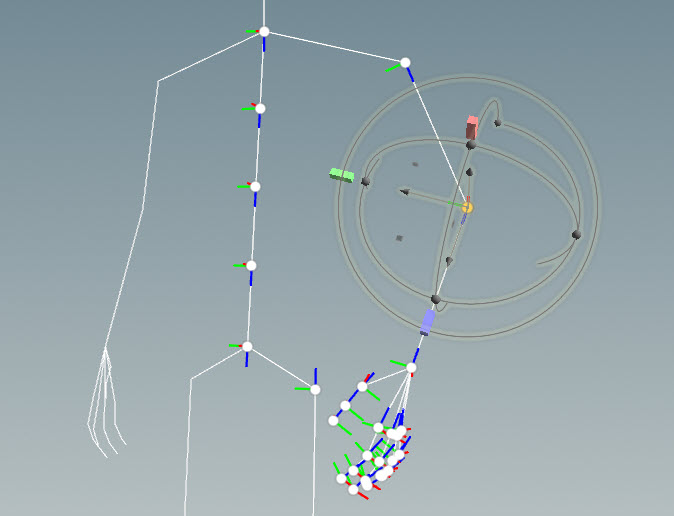
Set the main axis (primary axis) for the joint to rotate around. In this example, we set the primary axis to be the Z-axis because we want the Z-axis to remain as is (since it is pointing down the arm from the elbow to the wrist), and have the other axes orient themselves around the Z-axis. ⌃ Ctrl click the blue box shape at the end of the Z-axis handle; the box will change to a pyramid shape. The Z-axis is now set as the primary axis:
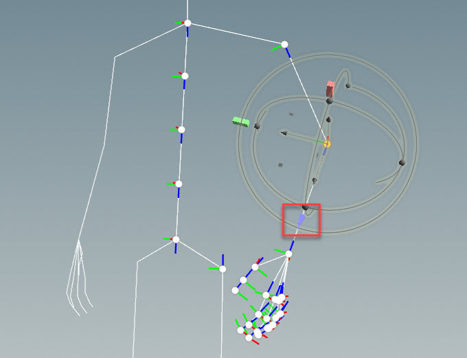
Set the secondary axis, which is the axis you want to line up with a particular link (line between joints). The joint will rotate around the primary axis to line up the secondary axis with the selected link.
In this example, we want to line up the X-axis with the shoulder-elbow link:
Click the red box at the end of the X-axis handle. The box will turn yellow to indicated that it is selected.
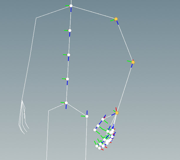
Click the shoulder-elbow link. Imagine a plane that includes the shoulder-elbow link and the elbow-wrist link. The X-axis will rotate about the Z-axis (primary axis) and align itself with this plane:
This technique gives nice orientations for elbows and knees:
Press ; to exit orientation picking mode.
You can orient joints by specifying the primary and secondary axes from the viewport state parameters:
Select the Skeleton SOP in your network.
Hover over the viewport and press Enter to enter the Skeleton viewer state.
![]() click in the viewport, and turn on Display Joint Axes.
click in the viewport, and turn on Display Joint Axes.
Hold S and drag to box select the joints you want to orient.
Hover over the viewport and press P to bring up the Parameters window.
In the Viewer State Dialog tab, set the Primary Axis and Secondary Axis:
Primary Axis
Axis that points toward the child.
Secondary Axis
Axis that points in the up direction.
![]() click in the viewport and select Orient Selected Joints. The axes in the joint chain will be updated.
click in the viewport and select Orient Selected Joints. The axes in the joint chain will be updated.
You can use the construction plane to adjust the joint rotation axes for a joint chain. In this example, we orient the axes of an elbow in a biped arm:
Select the Skeleton SOP in your network.
Hover over the viewport and press Enter to enter the Skeleton viewer state.
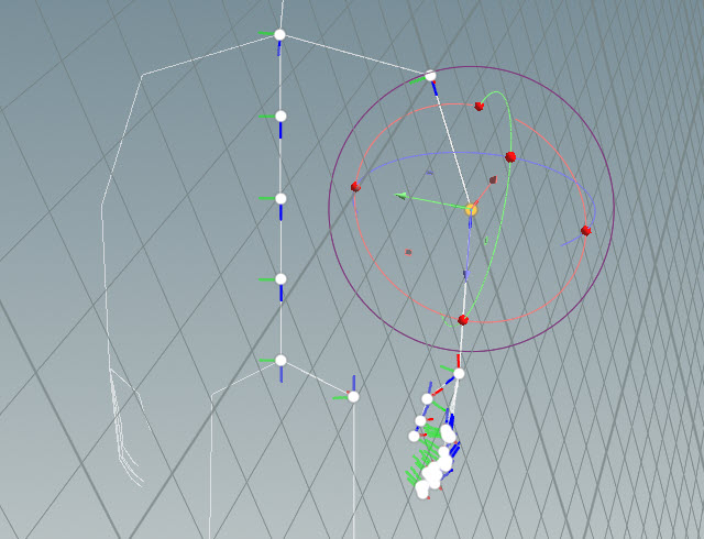
Select the joints surrounding the joint you want to orient. For example, if you want to orient the elbow, select the shoulder, elbow, and wrist joints:
Display the construction plane in the viewport by clicking ![]() on the right toolbar.
on the right toolbar.
![]() click in the viewport and select Orient Construction Plane to Selection. The construction plane will orient itself to the selected joints:
click in the viewport and select Orient Construction Plane to Selection. The construction plane will orient itself to the selected joints:
Select the joint(s) you want to orient. In this example, we select the elbow joint:
![]() click in the viewport and select Snap Selection to Construction Plane to update the joint orientation. This technique gives nice orientations for elbows and knees:
click in the viewport and select Snap Selection to Construction Plane to update the joint orientation. This technique gives nice orientations for elbows and knees:
You can quickly create a skeleton by drawing half a skeleton and using the ![]() Skeleton Mirror SOP to create joints for the other half:
Skeleton Mirror SOP to create joints for the other half:
We start with half a skeleton from our previous example:
Connect the Skeleton SOP to a Skeleton Mirror SOP.
Turn on the template flag for your character’s geometry node.
Select the Skeleton Mirror SOP and turn on its display flag. You can now see your character’s geometry while mirroring its skeleton:

Select the joints you want to mirror:
On the Skeleton Mirror SOP, click the Group parameter’s ![]() icon.
icon.
In the viewport, hold ⇧ Shift and drag to box select the joints you want to mirror (for example, all the limbs), and press Enter. The joints are added to the Group parameter.

Rename the mirrored joints. On the Skeleton Mirror SOP, set Token Position to Start, Find Tokens to L_, and Replace Tokens to R_. This find the joint names that start with L_, and replaces them with R_ for the mirrored joints. For example, if we have a joint named L_arm, its mirrored joint will be named R_arm.

Note
On the Skeleton Mirror SOP, the Mirroring Style parameter determines how the transforms of the original joints are mirrored to the new joints:
Choose By Rotation if you want to mirror the joints by rotating their input transforms. With this mode, any downstream posing can only be performed with FK rotations because the animated translations will be flipped. This is useful if you plan to pose the skeleton using only FK rotations, and do not want to negative scale any joints.
Choose By Scale if you want to mirror the joints by negative scaling their input transforms. With this mode, any downstream posing can be mirrored in both rotation and translation, but all the transforms will be negatively scaled. This may cause issues if you plan to export your skeleton to a game editor or other DCC.
You can blend between the transforms of two animation skeletons (whole or partial) with the ![]() Skeleton Blend SOP. This is useful when you want to blend a sparse hierarchy to a dense hierarchy, or vice versa.
Skeleton Blend SOP. This is useful when you want to blend a sparse hierarchy to a dense hierarchy, or vice versa.
In the example below, we blend an arm animation to a leg animation on the ![]() Electra test geometry:
Electra test geometry:
Set up the network to do skeleton blending:

The two ![]() Rig Pose SOPs animate two different movements.
Rig Pose SOPs animate two different movements.
Connect one of the animated skeletons to the Skeleton Blend SOP’s 1st input, and connect additional animated skeletons to the Skeleton Blend SOP’s multi-input.
The output of the Skeleton Blend SOP is the first input skeleton with the influence of the other skeleton(s).
The Joint Deform SOP allows us to see the deformed geometry.
On the Skeleton Blend SOP, adjust the weight sliders to control the amount of influence the different input skeletons have on the first skeleton. For example, setting the second skeleton’s slider to 0.5 results in the output skeleton using 50% of the second skeleton’s animation.
The Blend Masking parameter lets you choose how the weight sliders are used. You can select from three different modes:
No Masking
Uses the weight sliders to control the amount of influence the input skeletons have on the first skeleton.
Set From Attribute
Overrides the weight slider values with the attribute values from an upstream node. You can specify the attribute in Mask Attribute. This mode supports per-point blending.
Scale From Attribute
Uses the attribute values from an upstream node as a multiplier for the weight slider values. You can specify the attribute in Mask Attribute. This mode supports per-point blending.
Note
If you are blending animation skeletons in world space (World Space is turned on), the skeletons need to be in the same world space location before you use the blend operation.
| To... | Do this |
|---|---|
|
Move a joint and its descendants |
On the Skeleton toolbar, turn on Tweak Mode, and turn off Child Compensate. |
|
Move a joint without moving its descendants |
On the Skeleton toolbar, turn on both Tweak Mode and Child Compensate. |
|
Box select joints |
In the Skeleton viewer state, hold S and drag to select the joints. |
|
See the joint names in the viewport |
|
|
Fully expand a subtree in the rig tree view |
Hold ⇧ Shift and click a joint. |
APEX nodes provide operations for building up the functionality of APEX graphs, which are used in KineFX to create character rigs and perform other geometry manipulation.
A tree view of controls, selections, and selection sets for the animate state. Allows management of control selection and visibility.