| On this page |
|
One of the main purposes of the KineFX framework is to provide a clean, simple solution for transferring animation from one skeleton or rig to another and give you the tools to refine or clean-up the results of your retarget.
The core workflow associated with this framework is the animation retargeting workflow. Retargeting is the process by which you take the animation from one character (known as the source) and transfer it to a different character (known as the target).
Since KineFX is a robust and flexible system, it can handle many possible differences in morphology and hierarchical structure between the source and target characters.
For example:
-
Characters that have different units of measurements (for example, meters vs. centimeters)
-
Characters that have different limb proportions (for example, human vs. gorilla)
-
Characters with a different number of joints
-
Characters with different joint orientations.
Core retargeting workflow 
Note
A basic animation retarget uses the rest poses from the source and target characters when conforming their skeletons during the retarget process.
Step 1: Bring in the source and target 
-
In the Node Editor, do the following:
-
Create one KineFX import node for the source (mocap, animated skeleton, or animated character) of the animation that you want to transfer.
-
Create one KineFX import node for the target (static skeleton or character with skeleton deformations) you want to transfer the source animation to.
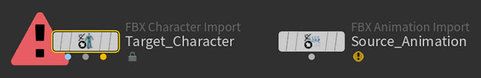
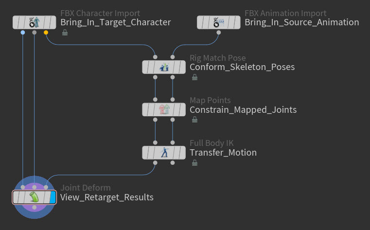
Example: Import nodes for a source animated skeleton and a target skinned character -
-
In the Parameter Editor for both the source and target KineFX import nodes, specify the skeleton or character files to use as their inputs.
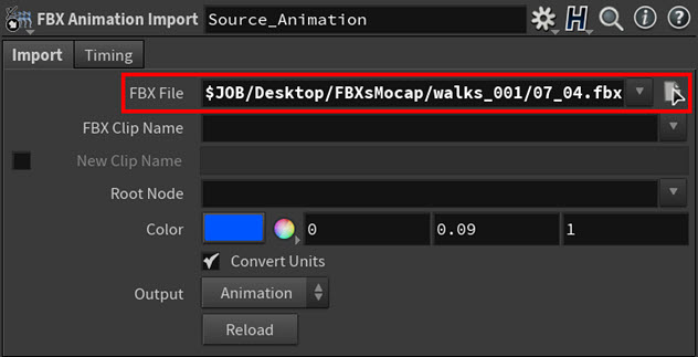
Example: Input file for the source KineFX import node 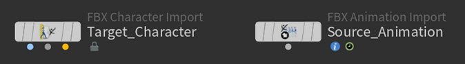
Example: Import nodes with specified inputs

Step 2: Match the poses of the source and target 
-
Create a
 Rig Match Pose SOP node.
The Rig Match Pose SOP node allows you to conform the source and target skeletons' poses in world space and then stores their joint transform values or rest poses as point attributes.
The FBIK (full-body IK) solver will then use the rest poses as one of the data points to compute the retarget.
Tip
The Rig Match Pose SOP node also allows you to match your source and target skeletons even if they have very different scales or proportions.
-
Do the following:
-
Connect the animated pose output from the source KineFX import node to the source skeleton (input 2) on the Rig Match Pose SOP node.
-
Connect the animated pose output from the target KineFX import node to the target skeleton (input 1) on the Rig Match Pose SOP node.
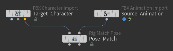
Example: Rig Match Pose connected to the source and target KineFX import nodes
-
-
Select the Rig Match Pose SOP node, click in the viewport, and then press Enter.
You are now in the Rig Match Pose interaction state.
In this state, you now have access to the Rig Match Pose toolbar and
 menu.
menu. 
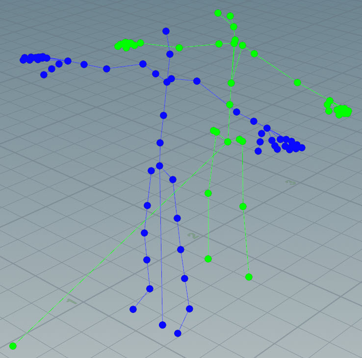
Example: Rig Match Pose state in the viewport You will also see the initial match in the viewport.
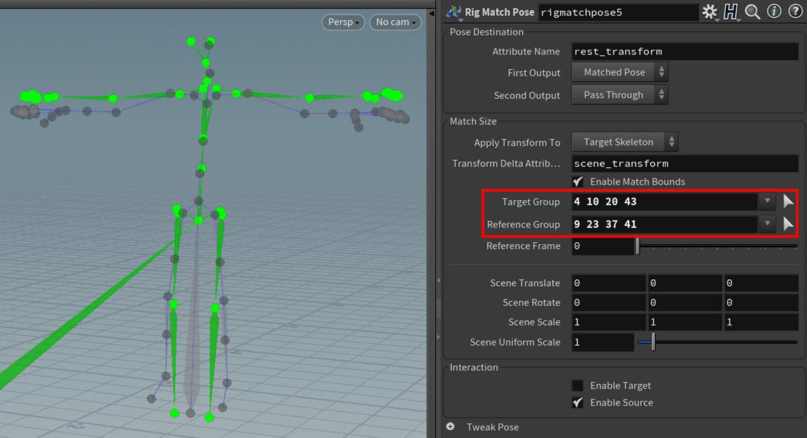
By default, the Rig Match Pose SOP will look at the bounding boxes of the source and target skeletons and then scale and translate their points to match. This behavior is enabled by the Match Size > Enable Match Bounds parameter on the Rig Match Pose SOP (which is on by default).
With the bounding box match, you can define two different point groups–one for the source (Reference Group field) and one for the target (Target Group)–that determine which of the source and target points to include in the bounding boxes. This is very useful if you want to exclude something like a tail or wings from the match. Also if your source and target skeletons are different sizes (for example, a human source and a halfling target), then this process will automatically resize them to match.
Tips
-
If you want to add all or most of the source and target points to the bounding box match groups, then please do not add their root joints to the groups. They are not necessary for the bounding box match and could potentially interfere with it.
-
You can get some really good results just by bounding box matching only the shoulder and hip joints from your biped skeletons.
Example: Bounding box match with shoulders and hips only
If you do not want to use bounding box matching, then you can turn off the Enable Match Bounds parameter and hand-edit 100% of the pose matching yourself.
-
-
If Enable Match Bounds is off or if you did not add any points to the Reference Group and Target Group fields in step 3, then select the global transform handle for the source and translate the source skeleton to the target skeleton’s position in world space. Try to overlap the two skeletons as much as you can.
If the source is a lot smaller/larger than your target, then please also use the global transform handle to scale up/down the source skeleton to match the size of the target skeleton.
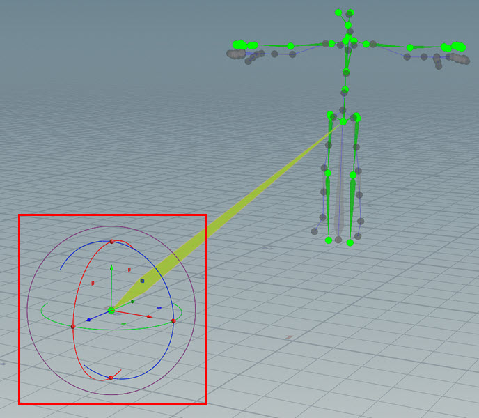
Example: Source skeleton global transform handle -
Tweak the global transformation of the source skeleton by rotating its joints so that each joint overlaps its counterpart in the target skeleton.
You do not have to be exact with the matching, but the goal is to remove as many offsets as you can from between the target and source skeletons.
Notes
-
Do not translate or scale the skeleton joints you see in the Rig Match Pose state.
-
By default, only the source skeleton is enabled for interaction. However, if you want to transform both skeletons while in the Rig Match Pose state, you can turn on Enable Target located in the Interaction section of the Rig Match Pose SOP's parameters.
Tip
When rotating the joints of your source skeleton, remember to view the skeleton from different angles and perspectives to make sure that everything lines up.
-
Rotate the source skeleton’s shoulder joints to align the arms.
-
Rotate the source skeleton’s hip joints to match the leg positions.
Example: Rotating the hip and shoulder joints -
For the last few adjustments, rotate joints like the elbow, wrist, knee, ankle, and head joints so that they overlap their counterparts in the target skeleton.
-
Your source skeletons should now be mostly occupying the same world space positions as its target skeleton counterpart.

Step 3: Map source points to target points 
-
Create a
 Map Points SOP node.
The Map Points SOP node creates references between source-target joint pairs and then stores those associations as mapping attributes. The source-target joint pairs have a constraint-like relationship.
The FBIK (full-body IK) solver will then use the mapping attributes to compute the offsets between the source and target joints in the joint pairs.
-
Do the following:
-
Connect the target skeleton output (output 1) from the Rig Match Pose node to the target skeleton input (input 1) on the Map Points SOP node.
-
Connect the source skeleton output (output 2) from the Rig Match Pose node to the source skeleton input (input 2) on the Map Points SOP node.
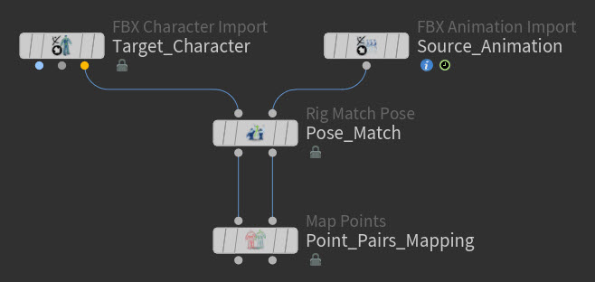
Example: Map Points connected to the Rig Match Pose node
-
-
Select the Map Points SOP node, click in the viewport, and then press Enter.
You are now in the Map Points interaction state.
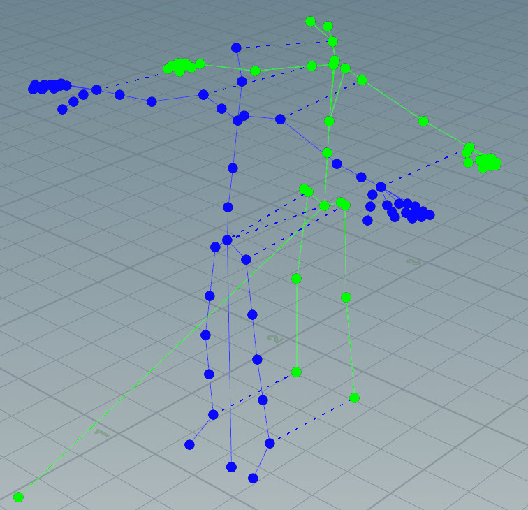
Example: Map Points state in the viewport Notes
-
The Rig Color parameters on your KineFX import nodes determine the colors of the Map Points skeletons.
-
-
Think about which type of FBIK solver you will want to use for your retarget.
-
If you plan to use the Physical Full Body IK solver, then that solver prefers a sparse mapping.
As such, you should only map the main, non-optional joint pairs for your skeletons. For example, the roots, hips, ankles, shoulders, wrists, and heads.
-
If you plan to use the FABRIK solver, then that solver prefers a dense mapping.
As such, you should map all the main and mobility joints pairs for your skeletons. For example, the roots, knees, hips, ankles, shoulders, elbows, wrists, spines, and heads as well as any other joints you deem beneficial to your mapping.
-
-
Map the joints of the target skeleton to their counterparts in the source skeleton.
-
 -click one joint and then its counterpart on the other skeleton to form a link between the joints.
This link appears as a dashed line between the joints in the viewport.
-
⇧ Shift-click one joint and then its counterpart on the other skeleton to mirror their mappings. The success of a mirrored mapping depends on the joint positions and the similarity of the point names in your skeletons. For example, if you ⇧ Shift-click the
l_shoulderon the source skeleton and then ⇧ Shift-click thel_shoulderon the target skeleton, then the right shoulders on both skeletons will also be mapped to each other. -
Select a joint and then ⌃ Ctrl-click on the background to remove that joint’s pair mapping.
-
Select a joint and then ⇧ Shift + ⌃ Ctrl-click on the background to remove that joint’s pair mapping as well as its mirrored joint pair’s mapping.
Example: Mapping joint pairs -
Your source skeleton skeleton and target skeletons should now be fully mapped.
Step 4: Transfer motion from the source to the target 
-
Create a
 Full Body IK SOP node.
The Full Body IK SOP node does the following for each frame of the source animation:
-
Computes the offsets between the joint-pairs you defined with the Map Points SOP in the rest poses you defined with the Rig Match Pose SOP.
-
Uses the offsets and source’s transforms to determine the transform goals or target positions for the joints in your target skeleton.
-
Moves or transforms the target skeleton’s joints to the target positions.
-
-
Do the following:
-
Connect the target skeleton output (output 1) from the Map Points SOP node to the target skeleton input (input 1) on the Full Body IK SOP node.
-
Connect the source skeleton output (output 2) from the Map Points SOP node to the source skeleton input (input 2) on the Full Body IK SOP node.
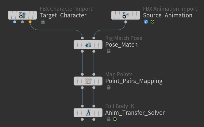
Example: Full Body IK connected to the Map Points node
-
-
Select the Full Body IK SOP node, click in the viewport, and then press Enter.
-
Playback your animation.
The target skeleton now appears to be driven by the source skeleton’s animation.
Tip
If your target character and source animation are different sizes, the ![]() Rig Match Pose SOP resizes its first input (target character) and stores the transform used for the resizing in the Transform Delta Attribute parameter. To reverse this resizing:
Rig Match Pose SOP resizes its first input (target character) and stores the transform used for the resizing in the Transform Delta Attribute parameter. To reverse this resizing:
-
Place a
 Transform By Attribute SOP after retargeting (after the Full Body IK SOP).
 -
On the Transform By Attribute SOP:
-
Set Transform Attribute to the attribute specified in the Rig Match Pose SOP’s Transform Delta Attribute parameter.
-
Turn on Invert Transformation.
-
This is only necessary if the Rig Match Pose SOP’s Apply Transform To parameter is set to Target Skeleton.
Step 5: View the results of the retarget 
-
Create a
 Joint Deform SOP node.
The Joint Deform SOP shows the results of the retarget operation in the viewport. If your target is a skinned character, then it will allow you see your animated character with all its skeleton deformations in the viewport.
-
Do the following:
-
Connect the target skeleton output (output 1) from the Full Body IK SOP node to the animated pose input (input 3) on the Joint Deform SOP node.
-
Connect the rest geometry output (output 1) from the target KineFX import node to the geometry to rest geometry input (input 1) on the Joint Deform SOP node.
-
Connect the capture pose output (output 2) from the target KineFX import node to the capture pose input (input 2) on the Joint Deform SOP node.
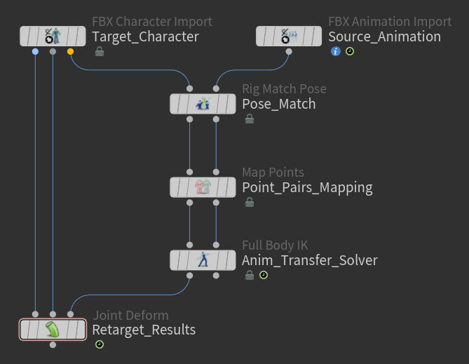
Example: Joint Deform connected to the Full Body IK and KineFX target import nodes
-
-
Playback your animation and view the results of the retarget in the viewport.
Example: Target skeleton with source animation. Character model courtesy of Christophe Desse. -
Select the
Full Body IK SOP node. -
In the Parameter Editor, set the
Full Body IK SOP node parameters to create the solver behavior you are looking for. -
Playback your animation again.
If the FBIK solver type you chose and the other settings you defined did not give you the retarget result you are looking for, then adjust the Full Body IK SOP node’s parameters settings some more (especially the Iterations) or switch its Solver type.
Continue to experiment with these settings until you get the results you want.
-
Clean up and refine the retarget results as needed.
For more information, see Refining the retarget result.
Animation retarget with a separate rest pose 
If the source for your retarget does not have a standard rest pose (like a t-pose), then this can make it very difficult to get a good match between poses for the retarget. For example, it is common for motion capture animation files to not have standard t-poses as their first frames.
To help in this situation, you can specify a new standard rest pose for a skeleton or character. This will make it a lot easier for you to conform your skeletons with the Rig Match Pose SOP as well as to optimize the results of the retarget operation.
How to 
-
Create a
 Rig Stash Pose SOP node.
The Rig Stash Pose SOP node will replace the rest pose in the source with a new rest pose.
-
Create the node that will hold the new rest pose.
For example, you could bring in a new rest pose in a number of ways like:
-
A
 File SOP that references a file on disk that contains a valid rest pose.
 -
A
 Stash SOP node that contains the state of a valid rest pose.
 -
Another KineFX animation import node whose animation skeleton contains a valid rest pose plus a
 TimeShift SOP node to freeze its animation in time at its rest pose.
Note
You can only use static transforms for the new rest pose.
-
-
Do the following:
-
Connect the output of the source’s KineFX import node to the rig input (input 1) of the Rig Stash Pose SOP.
-
Connect the output of the node you created in step 2 to the pose source (input 2) of the Rig Stash Pose SOP.
This node takes the source skeleton or character you want to define the new rest pose for as its first input and the new rest pose as its second input.
-
Connect the output of the Rig Stash Pose SOP node to the input of your retarget network’s Rig Match Pose SOP node.
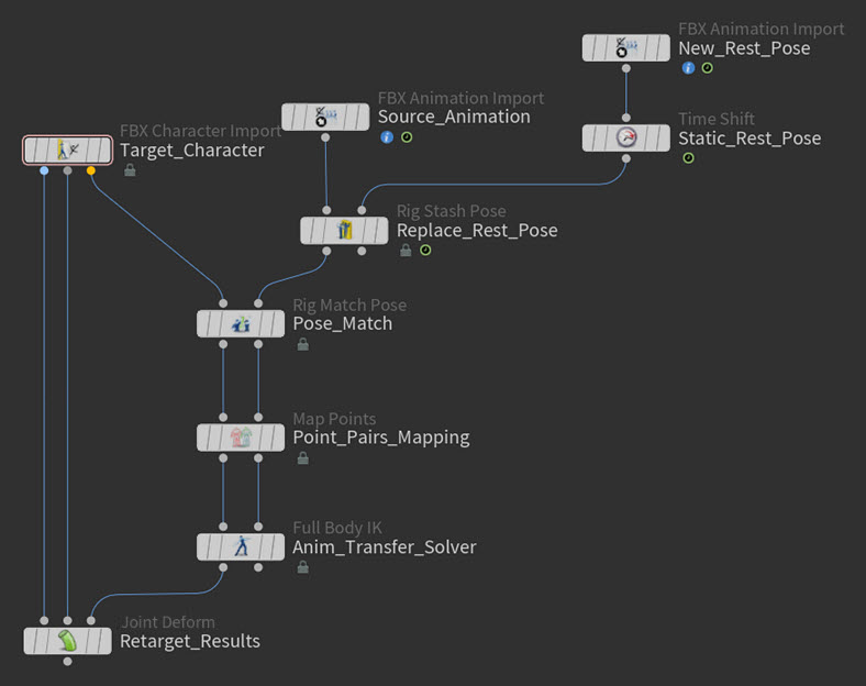
Example: New rest pose network -
The Rig Match Pose SOP in your retarget network will now use the new rest pose.
| See also |