| On this page |
After you have finished setting up the initial animation retarget between your source and target characters, you can refine the results of the retarget using a variety of techniques.
Example 1: Fixing sloped shoulders 
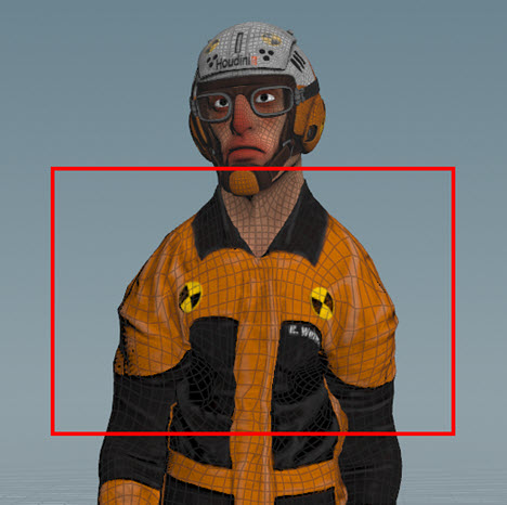
In this example, the character’s shoulders are severely sloped because the clavicles are not being constrained in any way during the FBIK solver’s computations.
To address this issue, there are two easy ways to add constraints to the clavicles during the FBIK solve:
-
Map the clavicles (see below)
-
Configure the joint behavior of the target’s clavicle joints.
Technique 1: Map the clavicles 
-
Select the
 Map Points SOP in you retarget network.
 -
Select the Map Points SOP node, click in the viewport, and then press Enter.
You are now in the Map Points interaction state.
-
⇧ Shift-click one of the clavicles on the source skeleton and then ⇧ Shift-click the corresponding clavicle on the target skeleton.
This will create joint pairs for both the left and right clavicles.
Example: Mapped clavicle joint pairs -
Select the
 Joint Deform SOP node in your retarget network and then playback your character’s animations to see the result of adding the clavicle joint mappings to the FBIK solve.
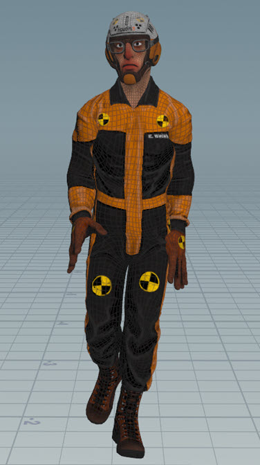
Example: Character’s shoulders before & after. Character model courtesy of Christophe Desse.
Technique 2: Configure the joint behavior of the target’s clavicle joints 
-
Create a
 Configure Joints SOP node.
The Configure Joints SOP will allow you to add limits to the clavicle joints on your target skeleton.
-
Do the following:
-
Connect the target skeleton output (output 1) of the
 Map Points SOP node to the target skeleton input (input 1) on the Configure Joints SOP node.
 -
Connect the target skeleton output (output 1) of the Configure Joints SOP node to the target skeleton input (input 1) on the
 Full Body IK SOP node.
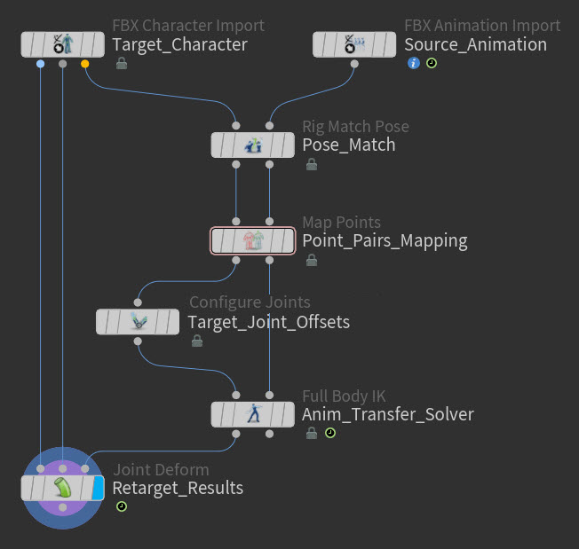
Example: Configure Joints SOP node in a retargeting network -
-
Select the Configure Joints SOP node and view its parameters.
-
Use the Configurations multiparm to create a new joint configurations group.
-
Click the Group parameter’s arrow selection icon, in the viewport ⇧ Shift-click both your character’s clavicle joints, and then press Enter.
The clavicle joints are added to the Group field.
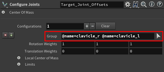
Example: Clavicles in the Group field -
Leave the Configure Joints SOP node selected, but turn on the Display flag for the
Joint Deform SOP node.You will now be able to see your characters skeleton deformations as you adjust its Configure Joints SOP.
-
Back in the Configure Joints SOP node’s parameters, adjust the Rotation Weights values until the roll of your character’s shoulders looks the way you want.
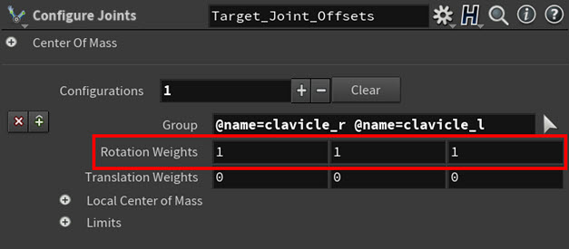
Example: Rotation Weights parameter Example: Adjusting the rotation weights for the clavicle joints. Character model courtesy of Christophe Desse. This adds rotation limits to the clavicle joints on your target skeleton such that the target clavicle joints will now try to maintain their original rest pose rotations.
-
Select the
Joint Deform SOP node in your retarget network and then playback your character’s animations to see the result of adding the clavicle joint rotation limits to the FBIK solve.Example: Character walk animation with its clavicles included in the FBIK solve. Character model courtesy of Christophe Desse.
Example 2: Stopping a reach animation from lifting the character’s feet off the ground 
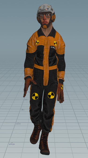
In this example, the character’s feet lift off the ground because the target skeleton can’t reach as far as the much larger source skeleton, but we want to ensure that the character’s feet remain firmly planted on the ground.

To address this issue, you can use a ![]()
![]() Configure Full Body IK Targets SOP node to increase the target’s influence on the feet and remove any translation offsets.
Configure Full Body IK Targets SOP node to increase the target’s influence on the feet and remove any translation offsets.
Technique: Increase the target’s influence on the feet and remove any translation offsets 
-
Create a Configure Full Body IK Targets SOP node.
The Configure Full Body IK Targets SOP will allow you to increase the influence of the target on the foot joints as well as remove any translation offsets from the feet.
Note
All the FBIK target configuration parameters and the Compute Offsets parameter appear in two different node locations:
-
Embedded inside the Full Body IK SOP node.
-
As part of the separate Configure Full Body IK Targets SOP node. This duplication of parameters is purely organizational. For this example, we are going to use the Configure Full Body IK Targets SOP node so that you can see how it should be inserted into your retarget network.
Warning
If you have target Configurations on both the Configure Full Body IK Targets SOP node and the Full Body IK SOP node, then you run the risk of configurations overriding each other. For example, if you have a target configurations group for the foot joints on both the nodes, then the settings on the Full Body IK SOP node will clobber those on the Configure Full Body IK Targets SOP.
-
-
Do the following:
-
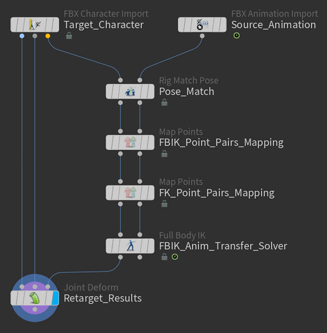
Connect both outputs from the
Map Points SOP node to both the inputs on the Configure Full Body IK Targets SOP node. -
Connect both outputs from the Configure Full Body IK Targets SOP node to both inputs on the
Full Body IK SOP.
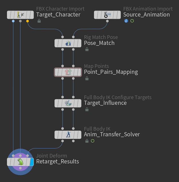
Example: Configure Full Body IK Targets SOP node in a retargeting network -
-
Select the Configure Full Body IK Targets SOP node and in its parameters, expand the Offsets section, and then turn on Compute Offsets.
The Compute Offsets parameter determines on which FBIK node the offsets between the source and target skeletons are computed.
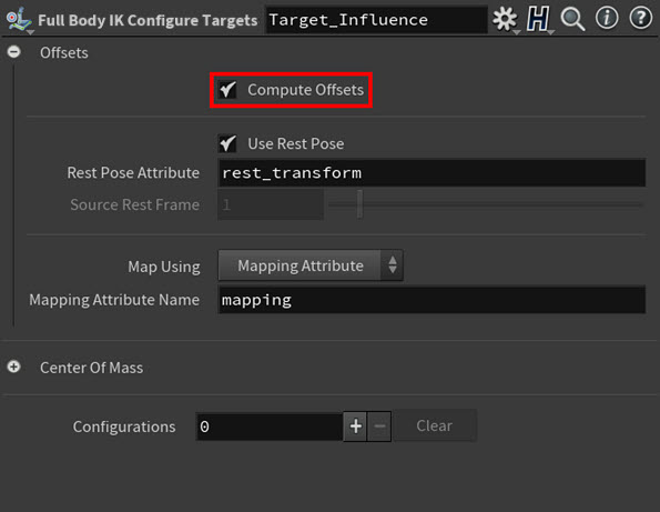
Example: Compute Offsets parameter -
Select the Full Body IK SOP node and in its parameters, turn off Offsets > Compute Offsets.
Now all the offset computations will be done by the Configure Full Body IK Targets SOP node.
You do not want to have Compute Offsets turned on for both nodes. You only need to run one compute offsets operation in the network.
-
Select the Configure Full Body IK Targets SOP node once again and in its parameters, use the Configurations multiparm to create a new target configuration group.
This Configurations multiparm entry will define the weights and offset behavior for a specific group of target joints.
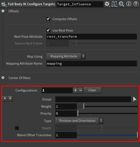
Example: Configurations multiparm -
Click the Group parameter’s arrow selection icon, in the viewport ⇧ Shift-click both your character’s foot joints, and then press Enter.
The names of the foot joints appear in the Group parameter’s field.
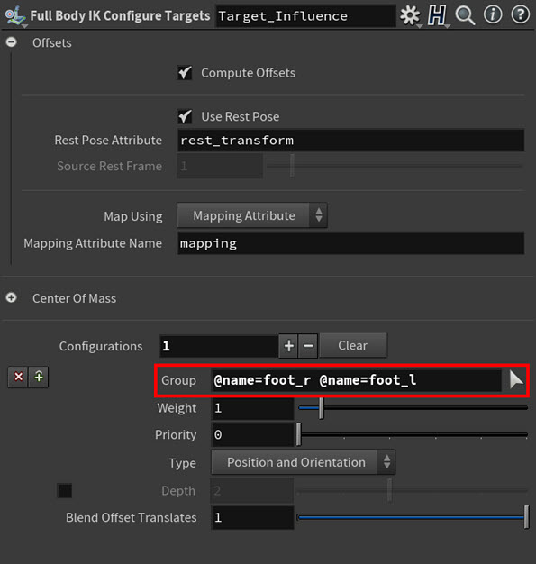
Example: Foot joints in the Group parameter field -
Increase the Weight value.
This will increase the amount of influence the target has on the foot joints, keeping the feet planted on the ground during the character’s reach animation.
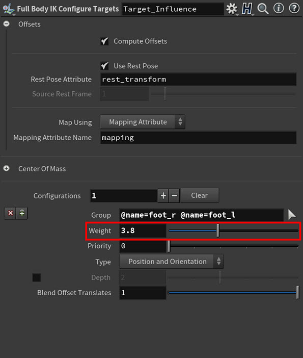
Example: Target influence weighting for the foot joints For example, for our character we increased the Weight to 3.8. This gives the target skeleton just enough influence to pull the character back to the ground.
-
Decrease the Blend Offset Translates parameter’s value.
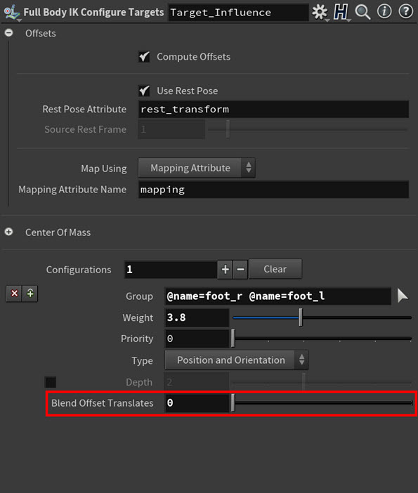
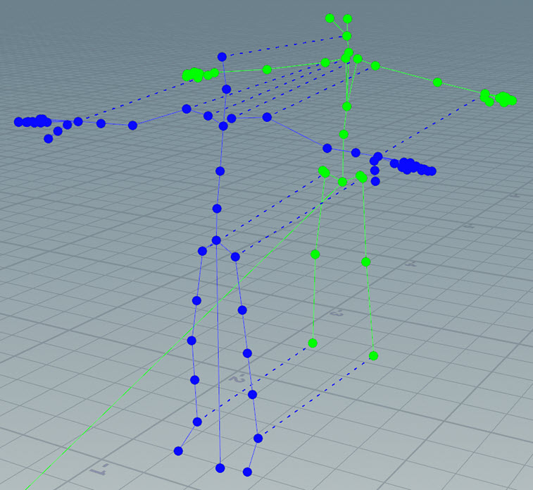
Example: Target translation offsets for the foot joints For example, for our character we will reduced the Blend Offset Translates to 0. If you look at the feet of our character’s source and target skeletons in the Rig Match Pose SOP node, you will notice that the feet are in wildly different positions. Turning the Blend Offset Translates down to 0 ignores that and causes the target’s feet to try and match the source skeletons foot positions.
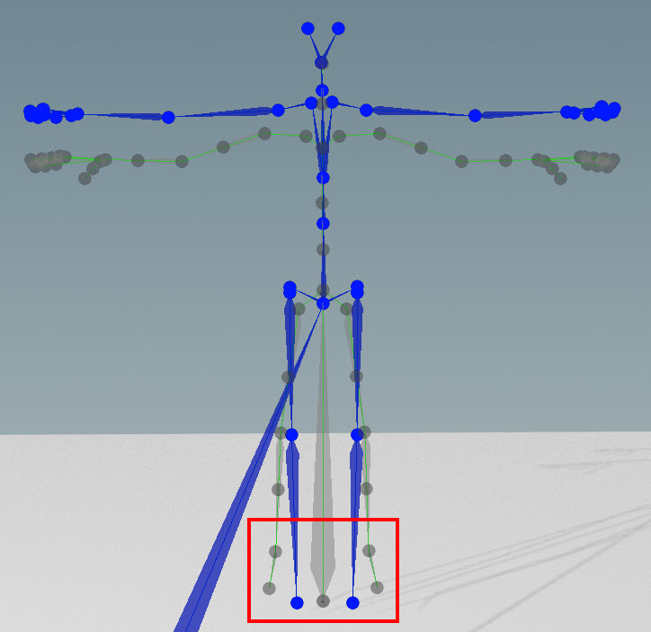
Example: Source and target skeletons' feet in their match poses -
Playback your animation to see the results of your tweaks to the target weighting and translation blending.
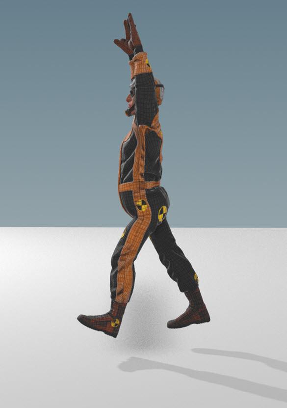

Example: Character’s feet placement before & after. Character model courtesy of Christophe Desse.
Example 3: Transferring fine finger movements 
Since ![]() FBIK is a holistic kinematics solver, adding a character’s finger joints to a FBIK retarget points mapping causes the effects of the fingers' animation to not only affect the hands of the character, but also the rest of the character’s body.
FBIK is a holistic kinematics solver, adding a character’s finger joints to a FBIK retarget points mapping causes the effects of the fingers' animation to not only affect the hands of the character, but also the rest of the character’s body.
To address this issue, you can use an ![]()
![]() FK Transfer SOP node to transfer the fingers' animation from the source to the target in local space.
FK Transfer SOP node to transfer the fingers' animation from the source to the target in local space.
Technique: Use FK transfer to retarget the character’s finger animation and fix the way its fingers curl 
-
Create a
Map Points SOP node.The Map Points SOP node creates references between source-target joint pairs and then stores those associations as mapping attributes.
-
Do the following:
-
Connect both outputs from your FBIK Map Points SOP node to both the inputs on the new FK Map Points SOP node you just created.
-
Connect both outputs from the FK Map Points SOP node to both inputs on your
Full Body IK SOP node.
Example: FK Map Points SOP node in the retarget network -
-
Select the FK Map Points SOP node and in its parameters, type
mapping_fkin the Mapping Attribute Name field.This will designate this node’s point mappings as being for the FK transfer and not for the FBIK solve (which already uses the
mappingattribute).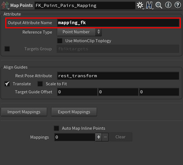
Example: Mapping Attribute Name for the FK Map Points SOP -
Click in the viewport and then press Enter.
You are now in the Map Points interaction state.
-
⇧ Shift-click one of the hand joints on the source skeleton and then ⇧ Shift-click the corresponding hand joint on the target skeleton.
This will create joint pairs for both the left and right hands.
Repeat these mirrored selections for each finger tip.
All the point mappings you created are now listed in the Map Points SOP parameters.
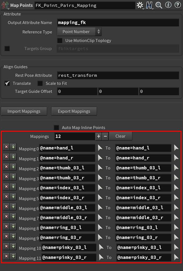
Example: Manual point mappings for the FK Map Points SOP -
In the Parameter Editor, turn on the Auto Map Inline Points parameter.
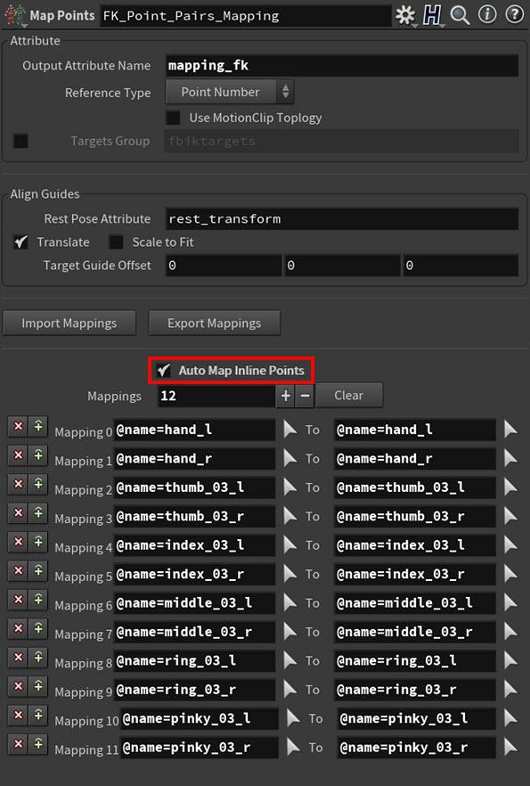
Example: Auto Map Inline Points parameter All the finger joints between the hand joint and finger tip joints are automatically mapped, and their point pair mappings are indicated by black dashed lines in the viewport.
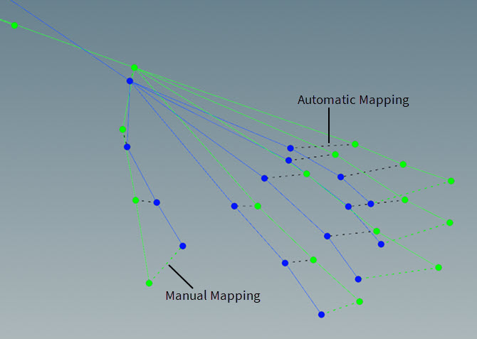
Example: Auto mapped finger points in the viewport -
Create an FK Transfer SOP node.
The FK Transfer SOP node will allow you to copy across the local space delta between the source animation and rest pose for a particular joint or group of joints.
-
Do the following:
-
Connect both outputs from the Full Body IK SOP node to both the inputs on the FK Transfer SOP node.
-
Connect the target skeleton output (output 1) from the FK Transfer SOP node to the deform point transform input (input 3) on the
Joint Deform SOP node.
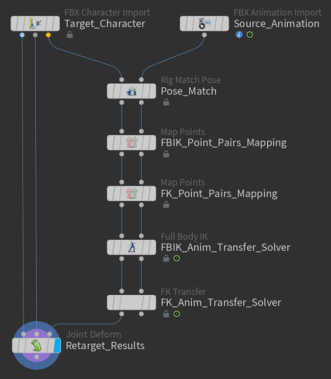
Example: FK Transfer SOP node in the retarget network -
-
Select the FK Transfer SOP node and in its parameters, do the following:
-
Click the Group parameter’s arrow selection icon, in the viewport ⇧ Shift-select the hand joint and all the finger joints, and then press Enter.
All the hand and finger joints are added to the Group field.
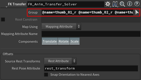
Example: Hand and finger joints in the Group field -
Type
mapping_fkin the Mapping Attribute Name field.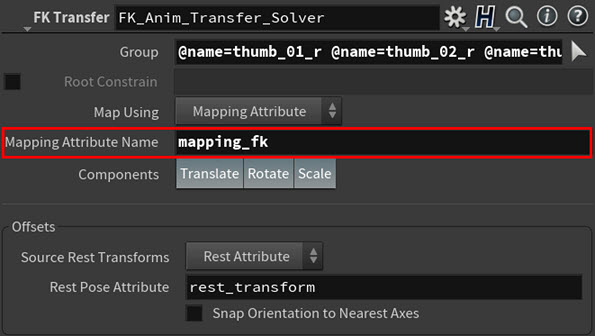
Example: Mapping attribute specified in the Mapping Attribute Name field The FK Transfer SOP node will now use the point mappings from the new FK Map Points SOP you created.
-
Turn on Snap Orientation to Nearest Axes.
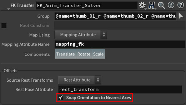
Example: Snap Orientation to Nearest Axes parameter Now when the FK Transfer SOP computes the offsets in orientation between the finger joints prior to doing the transfer, it will do an initial snapping to the transforms. This should improve the finger curling motions in the hands.
Note
The effectiveness of Snap Orientation to Nearest Axes relies on a reasonably matched set of source and target inputs.
-
-
Create a
 Rig Pose SOP node.
The fingers upturn a little too much in their animation, so we need to use the Rig Pose SOP node to add a few FK keys to correct this finger hyper-extension motion.
-
Do the following:
-
Connect the source skeleton output (output 2) from the Full Body IK SOP node to the input on the Rig Pose SOP node.
-
Connect output from the Rig Pose SOP node to the animated pose input (input 3) on the
Joint Deform SOP node.
Example: Rig Pose SOP node in the retarget network -
-
Select the Rig Pose SOP node, click in the viewport, and then press Enter.
You are now in the Rig Pose state.
-
Select the finger tip joints, scrub to the points in the animation where the fingers curl up the most, rotate the finger joints that are participating in the curl motions downward, and then key their new positions.
This should lessen the finger curl hyper-extension motions.
-
Playback your character’s animation to see the finger motion and the improved finger curling.
Example: Character’s final finger animation. Character model courtesy of Christophe Desse.
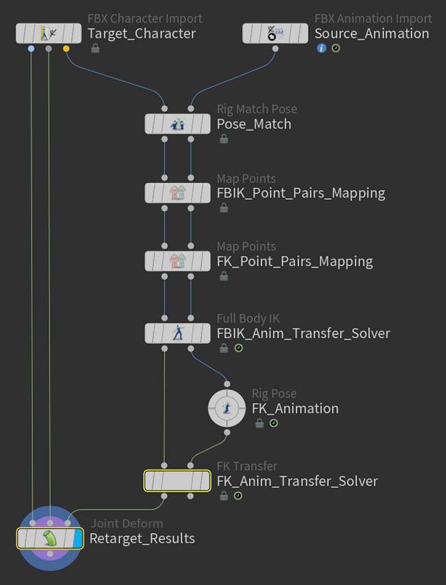
Example 4: Making a character appear to balance on a moving platform 
In this example, we want our character to act like it has mass and a sense of balance so that it appears to balance itself while standing on a moving platform.
To create this behavior, we will use the Center of Mass parameters with the ![]() Physical FBIK solver type.
Physical FBIK solver type.
Technique: Use center of mass to give your character the ability to balance and react to movement 
-
Do the following:
-
Create a
 Configure Joints SOP node. This will allow us to set up the center of mass capabilities.
 -
Create a
Rig Pose SOP node. This will allow you to pose your character’s joints while setting up the center of mass so that you can see the affect of the set-up steps on the character’s movements. -
Connect the animated pose output (output 3) from the KineFX character import node to the input of the Rig Pose SOP node.
-
Connect the output of the Rig Pose SOP node to the input of the Configure Joints SOP node.
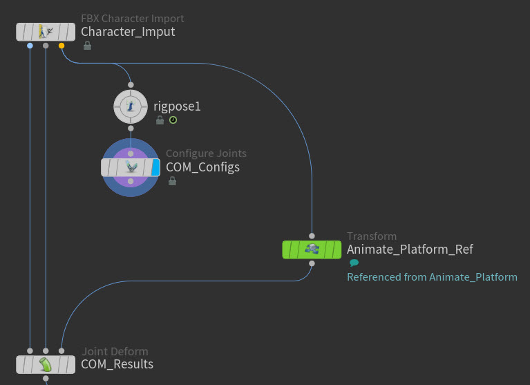
Example: Configure Joints SOP node in the network -
-
Select Configure Joints SOP and in its parameters, expand the Center Of Mass section.
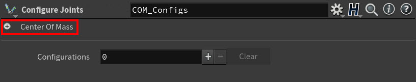
Example: Center of Mass parameters -
In the Center Of Mass section, turn on the Auto-Compute Joint Local Centers of Mass and Add Point at Center of Mass parameters.

Example: Center of Mass buttons This adds a new point to the skeleton that represents the center of mass.
Example: Center of Mass point’s affect on the skeleton -
Create a Delete Joints SOP node to create the point drivers for the center of mass.
-
Connect the output of Configure Joints SOP node to the input of Delete Points SOP node.
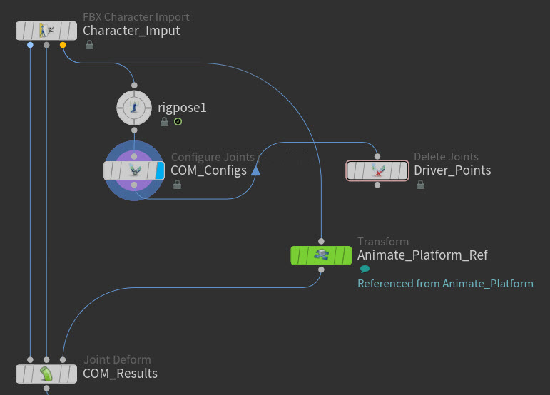
Example: Delete Joints SOP node in the network -
Do the following:
-
Select the Delete Joints SOP.
-
In the Delete Joints SOP's parameters, click the Group parameter’s arrow selection icon.
-
In the viewport, ⇧ Shift-select the COM point and both foot joints, and then press Enter.
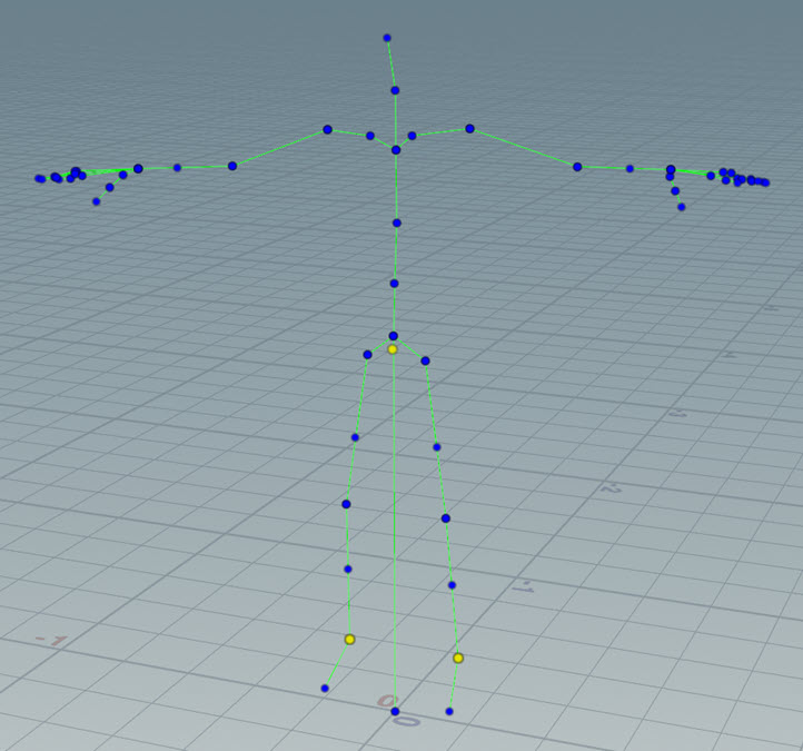
Example: COM point and both foot joints selected in the viewport The names of the COM point and both foot joints appear in the Group field.
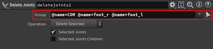
Example: COM point and both foot joints in the Group field
-
-
Select Delete Non-Selected from the Operation drop-down menu.
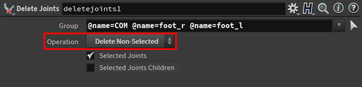
Example: Delete Non-Selected parameter You can now see the point drivers you created in the viewport. These points will help drive the center of mass movements.
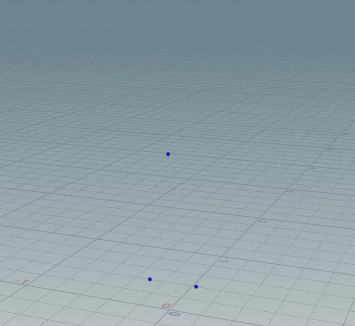
Example: Point drivers in viewport -
Create a Full Body IK SOP node.
-
Do the following:
-
Connect the output of Configure Joints SOP node to the target skeleton input (input 1) of the Full Body IK SOP node.
-
Connect the output of the Delete Points SOP node to the source skeleton input (input 2) of the Full Body IK SOP node.
-
Put platform’s transform node between the Delete Points SOP node and the Full Body IK SOP node.
-
Connect the target skeleton output (output 1) of the Full Body IK SOP node to the animated pose input (Input 3) on the Joint Deform SOP node.
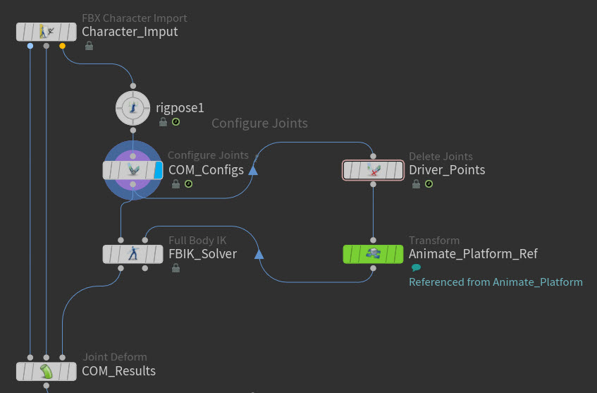
Example: Full Body IK SOP node in the network -
-
Select the Full Body IK SOP node and in its parameters, do the following:
-
Turn on Add Center of Mass Target.

Example: Add Center of Mass Target parameter -
Select Match by Attribute from the Map Using drop-down list.
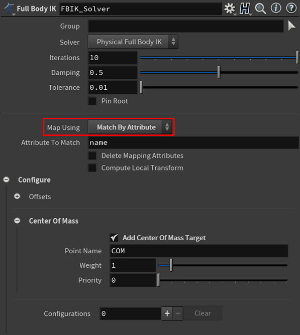
Example: Match by Attribute parameter
-
-
Add a Configurations multiparm and do the following:
-
Click the Group parameter’s arrow selection icon.
-
In the viewport, ⇧ Shift-select both the foot joints, and then press Enter.
The names of both the foot joints appear in the Group field.
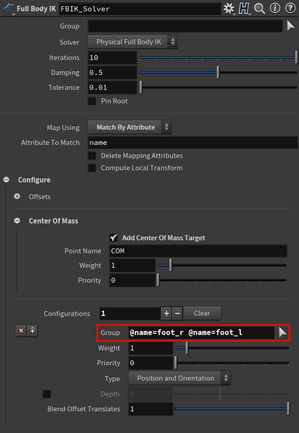
Example: Foot joint names in the Group field -
-
Increase the Configurations multiparm’s Priority to 1.
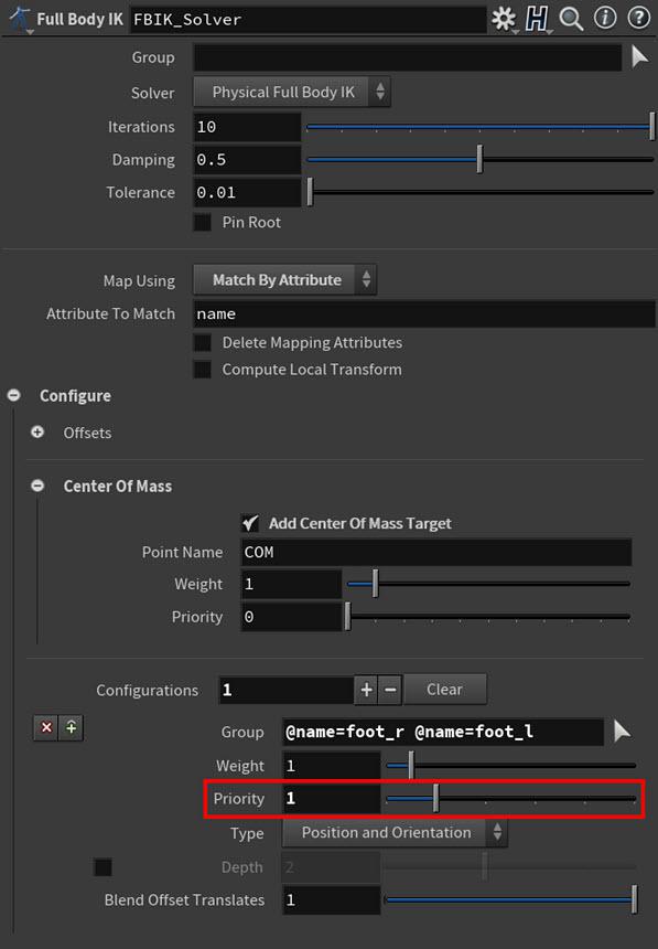
Example: Priority parameter The solver will now try to first achieve the foot transforms before it starts to look at the rest of the body’s joint transforms.
This will help stabilize the feet and keep them planted on the platform.
As the platform moves, you will now see the character striving to maintain its balance.
Example: Character balancing on platform. Character model courtesy of Christophe Desse. However, you may also see a little bit of jittering. This is common when working with different priorities and working with the Center of Mass target.
-
To combat the jittering and because the Physical FBIK solver likes to have a few more iterations, increase the Iterations to 150.
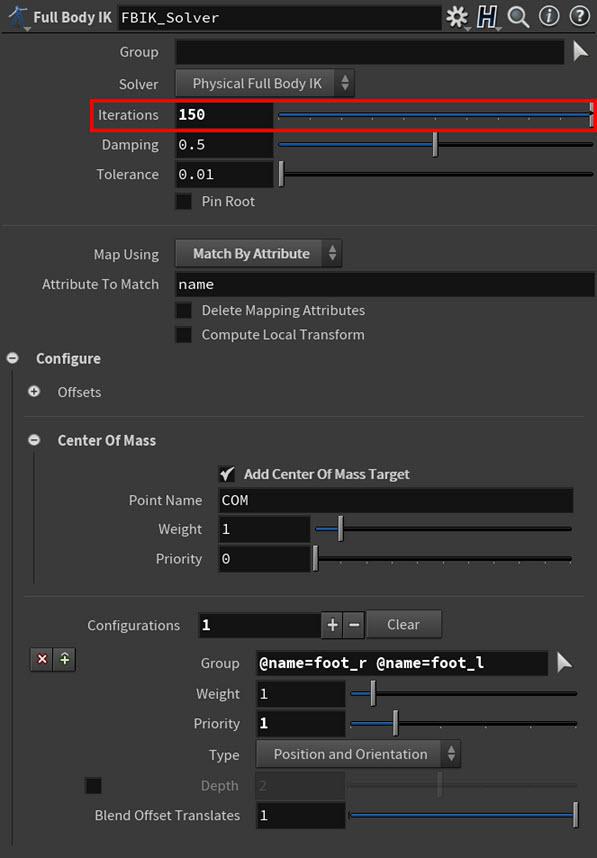
Example: Iterations parameter This will make the character’s balancing movement begin to look pretty convincing.
The arms and legs look a bit rigid though. To combat this, you can add a little bit of softness to the shoulder and knees joints.
-
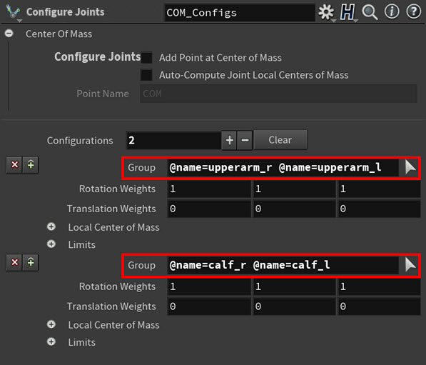
In the Configure Joints SOP node, create one Configurations multiparm for both shoulder joints and one for both knee joints.
-
For the shoulder joints, click the Group parameter arrow selection icon in the first Configurations multiparm. And in the viewport, ⇧ Shift-select the shoulder joints and then press Enter.
-
For the knee joints, click the Group parameter arrow selection icon in the first Configurations multiparm. And in the viewport, ⇧ Shift-select the knee joints and then press Enter.
The names of the shoulder and knee joints appear in their respective Group fields.
-
-
Increase the Rotation Weights values for both the shoulder and knee Configurations multiparms.
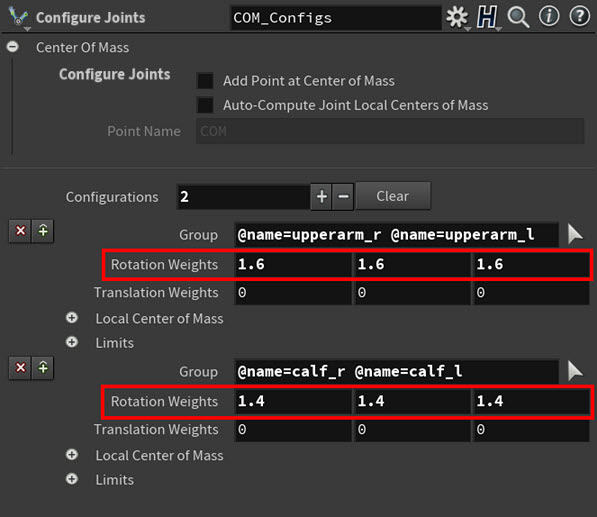
Example: Increased weights for the shoulders and knees This will cause the shoulders and knees to be slightly more willing to rotate than the other joints in the skeleton when the Full Body IK SOP node is trying to achieve the solve.
This adds an extra bit of realism to the way he is maintaining his balance.
Example: Final character balancing on platform behavior. Character model courtesy of Christophe Desse.
| See also |