On this page
This feature is still under development. The current functionality is unfinished and subject to change, and may have thin or no documentation. Please bear this in mind when using it.

Overview

The animate state is a viewer state that can display multiple characters in an animation scene and allow users to perform posing such as FK or IK for characters, interact with controls on characters, and add constraints between characters. Functionality like physics-based motion and ragdoll can also be applied to animation within the animate state.

To enter the animate state, select the APEX Scene Animate SOP in the network editor, turn on its display flag, and click Animate on the left toolbar.

Note

Only packed character elements can be displayed in the animate state. See the packed character format for information on how to prepare character data for the animate state.

Hotkeys

Hotkey or Interaction

Action

⌃ Ctrl + ⇧ Shift

With multiple controls selected, holding ⌃ Ctrl + ⇧ Shift puts the handle in global transform mode.

B

Displays a radial menu with the available tool options.

F

Frames the selected controls.

⇧ Shift + V

Toggles the display of the selection sets HUD.

V

Brings up a HUD window with a filtered list of the selection sets that contain selected controls.

MMB drag in empty space

Translates the selected controls.

P

Brings up the handle parameters window.

Y

Cycles through the different handle modes for the active handle.

T

Changes the active handle to translate mode.

R

Changes the active handle to rotate mode.

E

Changes the active handle to scale mode.

⌃ Ctrl

Holding ⌃ Ctrl while moving the different transform handles changes the handle component (translate, rotate, scale) by the step size set in the handle parameters window.

Animate mode

Hotkey or Interaction

Action

G

Select a control and press G to bring up a HUD window that allows you to change the transform components (translate, rotate, scale) of the selected control. You can also use the value ladder to change the component values.

⌃ Ctrl + G

Brings up a HUD window that allows you to change various settings including handle and framing options.

Locator tool

Hotkey or Interaction

Action

H

Creates a new locator at the mouse location. If a control is selected, creates a new locator at the location of the control handle.

⌃ Ctrl + H

Removes the selected locator.

mouse_wheel

Changes the shape of the selected locator.

⇧ Shift + mouse_wheel

Changes the size of the selected locator.

G

Brings up a HUD that allows you to change the color of the locator.

Constraints tool

Hotkey or Interaction

Action

H

Adds a constraint.

⌃ Ctrl + H

Removes a constraint.

G

Brings up a HUD with options for baking and turning on/off a constraint.

Dynamic motion tool

Hotkey or Interaction

Action

H

Pressing H the first time sets the center of mass control. Subsequently pressing H sets the start/end of a section of projectile motion.

⌃ Ctrl + H

Removes the current section of projectile motion.

G

Brings up a HUD for adjusting the projectile motion options.

⌃ Ctrl + G

Brings up a HUD with options for baking keys.

⇧ Shift + mouse_wheel

Changes the size of the selected projectile motion path ticks.

⌃ Ctrl + mouse_wheel

Changes the size of the selected projectile motion path height plane.

Ragdoll tool

Hotkey or Interaction

Action

H

Starts creating ragdoll for a character.

⌃ Ctrl + H

Removes ragdoll for a character.

G

Brings up a HUD for adjusting various ragdoll configuration parameters.

⌃ Ctrl + G

Brings up a HUD with options for reloading animation, visualizing the ragdoll simulation, and baking keys.

M

Enters an interactive mode for mapping character controls to ragdoll joints.

Transform handle

The handle in the animate state is used to select, manipulate, and transform characters and controls.
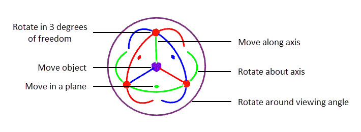
Transform handle modes

Press Y to cycle through the available transform handle modes.
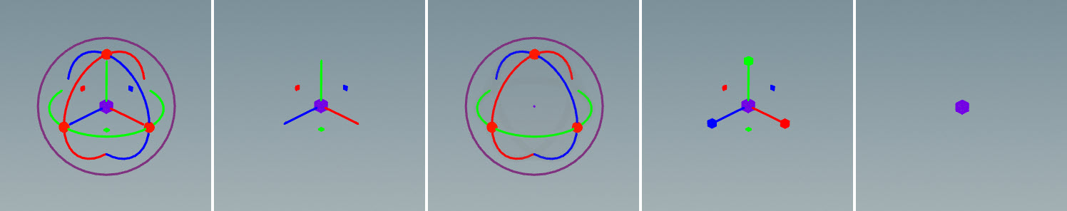
Animate state handle modes (left to right): full transform mode, translate mode, rotate mode, scale mode, minimized mode

See using handles for more information on the basic handle modes.

Handle context menu

The following options are available in the handle’s RMB menu:

Option

Functionality

Cycle Mode

Cycles through the different transform handle modes.

Xform Mode

Select a transform handle mode:

  • x - Full transform handle

  • t - Translate mode

  • r - Rotate mode

  • s - Scale mode

  • c - Minimized mode

  • Minimize All Xforms - If there are multiple handles in the scene, this option collapses all the handles to minimized mode.

Alignment

Determines how the transform handles are aligned.

  • world - Aligns the handle with the world axes. Does not rotate the actual control.

  • local - Aligns the handle with the control’s local transforms. Does not rotate the actual control.

  • c-plane - Aligns the handle with the construction plane; the handle axes are set by the construction plane. Does not rotate the actual control.

  • view - Aligns the handle with the view transform (the angle you are looking at the control). Does not rotate the actual control.

  • parent - Aligns the handle with the parent control. Does not rotate the actual control.

  • Separate Alignments - When turned on, unties the different components of the handle (translate, rotate, and scale). You can then choose to separately align the different components using the Translate Alignment, Scale Alignment, and Rotate Alignment options that show up under the Alignment setting when Separate Alignments is turned on.

  • World Axes - Rotates the control to align with the world axes, but does not change the handle alignment.

  • View Axes - Rotates the control to align with the view axes, but does not change the handle alignment.

  • C-Plane Axes - Rotates the control to align with the construction plane, but does not change the handle alignment.

  • Start Orientation Picking - Aligns the selected handle axis to templated geometry. Select Start Orientation Picking, click the handle axis you want to align, and click the point or edge of the geometry you want to align the axis to.

    Orientation picking
  • Cancel Orientation Picking - Cancel out of orientation picking mode.

Move Pivot

Moves the location of the control:

  • Move Pivot to World Origin - Moves the pivot to (0, 0, 0).

  • Move Pivot to C-Plane Origin - Moves the pivot to the origin of the construction plane.

  • Project Pivot onto C-Plane - Moves the pivot “up” or “down” onto the construction plane. The pivot is projected onto the construction plane at an angle perpendicular to the construction plane.

Snap To

When Pivot Mode is turned on, the pivot could be moved away from the control.

  • Snap Pivot to Centroid - Moves the pivot back to the control.

  • Snap Centroid to Pivot - Moves the control to the pivot.

Key Components

Sets keyframes for the translate, rotate, or scale components of the active handle.

Gimbal Mode

When Gimbal Mode is turned off, Houdini does background work so that you always see three rotation ring handles. When you drag a ring, the other rings rotate with it, regardless of the order of rotations.

The benefit is that it is impossible to gimbal lock the control axes by dragging the rotation handles. The downside is that in this mode, Houdini changes all three rotation components, not just the one you are dragging, and performing rotations this way can lead to very bad animation curves.

When Gimbal Mode is turned on, Houdini displays the true position of the rotation handles, and dragging the rotation handles changes the rotation components directly without Houdini trying to fix gimbal lock.

The benefit is that you have direct, independent control over the three rotation components, so you can use the handles to set up your animation without worrying about Houdini changing the other components. The downside is the possibility of gimbal lock.

For more information, see gimbal mode and fixing gimbal lock.

Pivot Mode

When turned on, you can move the handle away from the control so that the handle is offet from the control. When turned off, the handle is used as a pivot point for the control.

Revert to Default Values

Reset the handle values.

Handle parameter window

Press P when hovering over the viewport to bring up the handle parameters window.

Option

Functionality

Handle Translate Step

The step size to move the control when holding ⌃ Ctrl and moving the translate handle.

Handle Rotate Step

The number of degrees to rotate the control axes when holding ⌃ Ctrl and moving the rotate handle.

Handle Scale Step

The step size to scale the object when holding ⌃ Ctrl and adjusting the scale handle.

Handle Line Width

Adjusts the handle line thickness.

Handle Scale Factor

Adjusts the handle size.

Handle Brightness

Adjusts the handle brightness.

Draw Handles in All Viewports

When the viewport is split to show multiple views, turning this on displays handles in all the views. When turned off, only displays handles in the view that the mouse is hovering over.

Show Handle Plane Controls

When turned on, shows the handles that allow you to move the control in a plane.

Alternate Rotate Mode as Default

When turned on, continues rotating the control axes as you drag away from the rotate rings.

Pose Tools

Select the animate tool to use.

Use Click and Drag

When turned on, allows you to click and drag controls in one step. When turned off, controls need to first be selected, and then dragged in the next mouse action.

Use Control XRay

When turned on, controls are visible behind objects.

XRay Strength

Controls the opaqueness of controls behind objects.

Hide Controls During Playback

When turned on, hides controls when playing back the animation.

Selection sets and posing

Selection sets are used to organize controls into groups, or sets, in the animate state. These sets can then be used to select, hide, pin, and isolate groups of controls. See selection sets for more information.

Use selection sets to manipulate groups of controls

In the animate state, you can pose characters and set keyframes to perform animation. By default, when you select multiple controls and translate/rotate the active handle, the selected controls translate/rotate about their local axes.

Holding ⌃ Ctrl + ⇧ Shift puts the handle in global transform mode. When you translate the active handle, the selected controls translate in world space. When you rotate the active handle, the selected controls rotate about the active handle.

The videos below show the default and ⌃ Ctrl + ⇧ Shift behaviors when translating/rotating a group of controls.

Default translation behavior
Translation when holding Ctrl+Shift
Default rotation behavior
Rotation when holding Ctrl+Shift

In global transform mode, it is easy to pose characters in a variety of configurations by translating and rotating groups of controls about the last selected pivot. This can be done without the use of constraints.

Rotating controls about the last selected pivot
To...Do this

Rotate about the last selected control

  1. Select the group of controls (or selection set) you want to rotate about a pivot control.

  2. Hold ⇧ Shift while selecting the pivot control.

  3. If necessary, change the handle mode to one that has rotation handles (press Y to cycle through the different handle modes, or press R to change the handle to rotate mode).

  4. Hold ⌃ Ctrl + ⇧ Shift and drag the rotate handles to rotate the group of controls about the pivot control.

Rotate about the last selected control

Adjust the transform component values (translate, rotate, scale) of a control

  1. Select a control.

  2. Press G to bring up a HUD window that allows you to change the transform component values of the selected control. You can also use the value ladder to change the component values.

Change the handle alignment

  1. Press ⌃ Ctrl + G to bring up a HUD that allows you to change various handle settings.

  2. In the Handle Align option, select to align the handle to the world axes, local axes, construction plane, view angle, or parent control.

Keep the same transform handle mode when selecting different controls

  1. Press ⌃ Ctrl + G to bring up a HUD that allows you to change various handle settings.

  2. Turn off Auto Handle Xform Mode.

  3. In the Handle Mode option, select the transform handle mode you want displayed.

Change the amount of zoom when framing a selection

  1. Press ⌃ Ctrl + G to bring up a settings HUD.

  2. Adjust the Framing Zoom option.

Turn on gimbal mode

  1. Press ⌃ Ctrl + G to bring up a settings HUD.

  2. Turn on Use Gimbal Mode.

You can also turn on gimbal mode by RMB clicking in the viewport, and turning on Gimbal Mode.

Animate state tools

The following tools are used to add different functionality to your animation within the animate state:

Locator

Add locators to use as pivot points for controls.

Constraints

Add constraints between controls.

Dynamic motion

Replace animation curves with projectile motion.

Ragdoll

Add a ragdoll simulation to your animation.

The tools can be selected from the top toolbar in the animate state, as well as from the animate state radial menu. Press B when hovering over the viewport to bring up the radial menu.

Tools radial menu

Locator tool

A locator is an element that is added to the animate state for use as a pivot point for rotating groups of controls. It can be used to perform FK-type posing for a character. A locator is not part of the rig.

To enter the Locator tool, click Locator on the top toolbar, or select Locator from the radial menu.

To...Do this

Create a locator as a pivot

Place your mouse over the desired locator position, and press H.

Rotate about a locator / Perform FK-type posing

  1. Select the locator.

  2. Select the selection set or group of controls you want to rotate about the locator.

  3. Hold ⌃ Ctrl + ⇧ Shift when rotating.

Note

If you don’t hold ⌃ Ctrl + ⇧ Shift when rotating groups of controls, all the controls will rotate about their local axes. See global transform mode.

Rotate about locator
FK-type posing

Change the size and shape of a locator

mouse_wheel changes the shape of the selected locator.

⇧ Shift + mouse_wheel changes the size of the selected locator.

Change the color of a locator

Press G to bring up a HUD to set the color of the locator.

Constraints tool

Constraints create a parent-child relationship between controls, where the child control follows the parent control.

To enter the Constraints tool, click Constraints on the top toolbar, or select Constraints from the radial menu.

To...Do this

Add a constraint

  1. Select the child control.

  2. Hold ⇧ Shift and select the parent control. A dotted line will appear with an arrow pointing from the parent to the child.

  3. Press H. A constraint will be added, and the child control will turn gray.

In the below example, the right hand initially comes off the pole. Once a constraint is added, the right hand stays on the pole.

Before adding a constraint on the right hand
After adding a constraint

Remove a constraint

Select the child control and press ⌃ Ctrl + H. The child control will change back to its original color.

Turn a constraint on or off

  1. Select the child control.

  2. Press G to bring up the HUD.

  3. Turn on or off the Enable Constraints option.

Bake the constraint over a frame range

  1. Select the child control.

  2. Press G to bring up the HUD. Make sure Enable Constraints is turned on.

  3. Select a frame range on the playbar.

  4. Click Bake Range.

Keyframes will be added to every frame in the selected frame range. If you turn off Enable Constraints, the child control will still look like it is constrained to the parent within the frame range.

Update existing keyframes over a frame range to match the constrained position

Similar to Bake Range, but only updates the existing keyframes.

  1. Select the child control.

  2. Press G to bring up the HUD. Make sure Enable Constraints is turned on.

  3. Select a frame range on the playbar.

  4. Click Update Range.

If you turn off Enable Constraints, the child control will still match the constrained position at the existing keyframes.

Dynamic motion tool

The dynamic motion tool allows you to add physically-accurate projectile motion trajectory to your animation. See physics-based motion for more information.

To enter the dynamic motion tool, click Dynamic Motion on the top toolbar, or select Dynamic Motion from the radial menu.

Create projectile motion

To replace the current motion paths in an animation with projectile motion:

  1. Select the center of mass control(s) that will be used to calculate the projectile motion path, and press H. The path of the current keyframed animation with rough posing will be shown.

    Animation trajectory with rough posing
  2. Set the start and end of a section of projectile motion.

    • On the playbar, move the animation to the start of the first jump, and press H. A green arrow indicates the start of the projectile motion section.

    • Move to the end of the first jump, and press H. A red arrow indicates the end of the projectile motion section. The path of the first jump will be replaced with projectile motion.

    Replace path with projectile motion
  3. Add projectile motion for the remaining jumps.

    Animation with projectile motion

Put projectile motion back onto the animation

At this point, the projectile motion can only be seen within the Dynamic Motion tool, and not in the default Animate mode. To put the projectile motion back onto the original animation:

  1. Press Ctrl+G to bring up the HUD.

  2. Click Update Keys.

The existing keyframes will be moved to the projectile motion path.

To...Do this

Adjust the height of the projectile motion

Select the height plane that appears at the top of the projectile motion arc, and adjust the height using the handles.

Note

Select the height plane and press R to switch the transform handle to rotate mode. This allows you to rotate the plane so that the projectile motion path skims the plane instead of reaching a specific height.

Change height of projectile motion arc

or

  1. On the playbar, move the animation to within the frame range of the projectile motion section.

  2. Press G to bring up the HUD, and adjust the Life option.

Change the start and end positions of the projectile motion section

Select the green/red arrow at the start/end of the projectile motion path, and adjust the position using the handles.

Change projectile motion start and end positions

Put the projectile motion back onto the animation

Moves the existing keyframes to the projectile motion path.

  1. Press Ctrl+G to bring up the HUD.

  2. Click Update Keys.

Add additional keyframes to the projectile motion regions

  1. Press Ctrl+G to bring up the HUD.

  2. The following options are available:

    Keep Existing Keys

    When turned off, the existing keys are replaced by the new keys.

    Bake Essential Keys

    When turned on, adds keyframes at the most important points of the arc - the landing points, halfway up the arc on either side, and the peak of the arc.

    Resample Keys and Every N Frames

    When turned on, resamples the projectile motion regions Every N Frames.

  3. Click Bake to Keys.

Change the size of the projectile motion path ticks

⇧ Shift + mouse_wheel

Change the size of the projectile motion height planes

⌃ Ctrl + mouse_wheel

Ragdoll tool

The ragdoll tool allows you to add a ragdoll simulation to your animation.

To enter Ragdoll mode, click Ragdoll on the top toolbar, or select Ragdoll from the radial menu.

In this example, we will add ragdoll to the top character.

Starting animation

Note

Before using the ragdoll tool in the animate state, ragdoll collision shapes need to be set up (Ragdoll Collision Shapes SOP) and joint limits configured (Configure Joint Limits SOP) for your character.

Set up

  1. Press H to start creating a ragdoll simulation.

  2. In the Character Source Data window, select the skeleton (.skel) of the character you want to turn into a ragdoll. Click Accept.

  3. Select the ragdoll collision shapes that were previously set up for the character. Click Accept.

    The collision shapes are generated by the 2nd output of the Ragdoll Collision Shapes SOP. If these collision shapes are packed into the character and named, say, RagdollCollision.shp, then select the RagdollCollision.shp that appears under the character (.char).

    If you bring in a copy of a character that is already in the scene, but don’t have collision shapes for the new character, you can use the collision shapes on the original character.

  4. Select the animation channel data you want to use. If this is a new ragdoll simulation, you don’t need to select anything. Just click Accept.

    If you have previously configured ragdoll data and want to use the stored animation channel data, select ragdolldata > *_channelprims, and click Accept.

    Note

    Channel primitives are animation curves that are stored along with the geometry and are optimized for the animate state. When a control on a character is selected, channel primitives for that control are added to the channel list, and you can interact with them like regular channels.

  5. Select the MotionClip you want to use. If this is a new ragdoll simulation, you don’t need to select anything. Just click Accept.

    If you have previously configured ragdoll data and want to use the stored MotionClip, select ragdolldata > *_motionclip.

  6. Enter a name for the ragdoll, and click OK.

  7. Specify where to look for the original animation that the ragdoll inherits.

    We want the ragdoll to inherit the original animation of the character before the ragdoll simulation takes over. On the character rig, the movement of the skeleton is driven by the animation. The skeleton input of the rig is in its rest pose. The skeleton output of the rig has updated positions that are driven by the animation. This skeleton output is used to build a MotionClip, which stores a set of skeleton poses over a frame range.

    In the dialog, specify the skeleton output (.skel) of the source character rig. The character format hierarchy is as follows: character > rig > rig output node > skeleton output. For example:

    character
      -- Base.rig
        -- output
          -- Base.skel
    
  8. Click Accept.

    You will see the character’s collision shapes. If you play the animation, the ragdoll will fall on the ground plane, which is the basic default behavior for a ragdoll character.

    Default ragdoll behavior

Create the ragdoll motion

  1. To have a better view of the ragdoll, press ⌃ Ctrl + G to bring up a HUD, and click Toggle Visualiser Offset. This places the ragdoll to the side of the source character.

    Visualize ragdoll

    Note

    If the ragdoll controls don’t show up, make sure that visibility for ragdoll is turned on under the All Controls selections set.

  2. Set the spine joints to follow the animation, while the rest of the character stays as ragdoll.

    • Select the collision shapes along the spine and press G to bring up a HUD to configure the collision shape parameters.

    • In the Animated tab, turn on Match World Transforms. The joints in the selected collision shapes will follow the original skeleton joints.

      When Match World Transforms is turned on, a keyframe is set at the current frame for each of the selected joints. Channels for the selected collision shape joints will appear in the channel list appended with _matchworldtransforms.

    Partial ragdoll

    Tip

    If the collision shapes are jittering, it could be that they are colliding against each other. Try turning off Active instead of turning on Match World Transforms.

    Collision shapes jittering
  3. Specify that the ragdoll simulation takes over at the end of the throw. Go to the frame where you want the ragdoll simulation to take over, and turn off Match World Transforms. Keyframes will be set on the selected *_matchworldtransforms channels.

    Switch to full ragdoll at the end of the throw

Put the ragdoll simulation back onto the animation

  1. Map the source skeleton controls to the ragdoll joints.

    Press M to enter the interactive mapping mode. This works similar to the Map Points SOP.

    Map source skeleton controls to ragdoll joints
  2. Select the controls that have the ragdoll motion you want to put back onto the animation. You can also create a selection set for the group of controls, and select the set from the selection sets HUD or pane.

  3. Press ⌃ Ctrl + G to bring up a HUD with the following baking options for writing out the ragdoll motion to the animation:

    Bake Keys

    Adds a keyframe at a particular frame.

    Start Recording Poses

    Sets keyframes on selected frames or over a frame range.

  4. Click Start Recording Poses.

    If you select certain frames on the timeline, keyframes will be added at those frames.

    If you scrub the timeline, keyframes will be added to every frame in the frame range while scrubbing.

    If you press the Play button on the playbar, keyframes will be added to every frame until you press the Stop button.

  5. Click Stop Recording Poses when you have added all the keyframes you want.

The animation will now include ragdoll motion.

Ragdoll motion written out to the animation
To...Do this

Start creating a ragdoll

Press H and follow the prompts.

Display the ragdoll collision shapes off to the side of the animation

  1. Press ⌃ Ctrl + G to bring up the action buttons HUD.

  2. Click Toggle Visualiser Offset.

Set the status of whether or not a character is a ragdoll at a particular frame

  1. Press G to bring up the configuration parameters HUD.

  2. Select the Animated tab.

  3. Select any collision shape on the character.

  4. Turn on or off Character Active. This setting is per character.

    When turned on, the character becomes a ragdoll at the current frame. When turned off, the character is no longer a ragdoll at the current frame, but other objects can still collide against it.

    When the Character Active setting is updated, a keyframe is set on the globalactive channel that appears in the channel list.

Set certain collision shapes to follow the original animation

  1. Select the collision shape(s).

  2. Press G to bring up the configuration parameters HUD.

  3. Select the Animated tab.

  4. Turn off Active. This setting is per collision shape.

Other objects can still collide against the collision shape.

Set certain collision shapes to not collide with other shapes

  1. Select the collision shape(s).

  2. Press G to bring up the configuration parameters HUD.

  3. Select the Animated tab.

  4. Turn on Disable Collisions. This setting is per collision shape.

Set certain joints to match the joint positions of the original skeleton

  1. Select the collision shape(s).

  2. Press G to bring up the configuration parameters HUD.

  3. Select the Animated tab.

  4. Turn on Match World Transforms. A keyframe will be set at the current frame for each of the selected joints. Channels for the selected collision shape joints will appear in the channel list appended with _matchworldtransforms.

  5. Optionally adjust the Position Stiffness, Position Damping, Orientation Stiffness, and Orientation Damping values.

The selected joints will follow the original skeleton joints, while the rest of the character will be ragdoll.

Bring in other objects that can collide with the ragdoll

  1. Add the object to the scene as a prop rig.

  2. Set up ragdoll collision shapes (Ragdoll Collision Shapes SOP) for the object.

  3. In the scene, set up the object as a ragdoll.

Reload a MotionClip in the scene

  1. Press ⌃ Ctrl + G to bring up the action buttons HUD.

  2. Click Reload Target Animation.

Pin unattached collision shapes to the skeleton

  1. Press G to bring up the configuration parameters HUD.

  2. Select the Constant tab.

  3. Turn on Solver Pin Root.

This is a global option that applies to all the characters. See Pin Root in the Ragdoll Solver SOP for more information.

Change the density, bounce, and friction of the collision shapes

  1. Select the collision shape(s).

  2. Press G to bring up the configuration parameters HUD.

  3. Select the Constant tab.

  4. Adjust the Density, Bound, or Friction parameters. These values are configured per collision shape.

Turn on or off the ground plane

  1. Press ⌃ Ctrl + G to bring up the action buttons HUD.

  2. Select the Ground Plane tab.

  3. Turn on or off Enable.

Show or hide the ground plane

  1. Press G to bring up the configuration parameters HUD.

  2. Select the Ground Plane tab.

  3. Turn on or off Display.

Descriptions for the parameters in the configuration parameters HUD (G hotkey) can be found in the Ragdoll Solver SOP node doc.

KineFX

Preparing rig inputs

Procedural Rigging

Deformation

Animation

Appendix

Animation Retargeting

KineFX 19.5 functionality

Compatibility

Panes