| On this page |
|
You can create simulated motion and collision effects for your characters by running them through an RBD (rigid body dynamics) simulation using the ![]() Ragdoll Solver SOP. The
Ragdoll Solver SOP. The ![]() Configure Joint Limits and
Configure Joint Limits and ![]() Ragdoll Collision Shapes SOPs perform setup steps that are used in the ragdoll simulation.
Ragdoll Collision Shapes SOPs perform setup steps that are used in the ragdoll simulation.
The steps for creating a ragdoll simulation are:
-
Set joint limits on the character skeleton.
-
Create ragdoll collision shapes.
-
Run the ragdoll simulation.
-
View the simulation results.
The following workflow adds a ragdoll simulation to the ![]() Electra test geometry:
Electra test geometry:
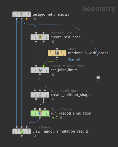
On the Electra test geometry, set the Output parameter to Skin Surface.
The ![]() Rig Stash Pose SOP creates the rest pose for the character by storing the
Rig Stash Pose SOP creates the rest pose for the character by storing the rest_transform attribute that is used later by the ![]() ragdoll solver.
ragdoll solver.
Set joint limits 
The ![]() Configure Joint Limits SOP provides an interactive way of setting and modifying joint limits for a skeleton. The joint limits are created in the Configure Joint Limits viewer state:
Configure Joint Limits SOP provides an interactive way of setting and modifying joint limits for a skeleton. The joint limits are created in the Configure Joint Limits viewer state:
-
Select the Configure Joint Limits SOP.
-
Press Enter over the viewport, or click
 on the left toolbar to enter the Configure Joint Limits viewer state.
 -
By default, the Rotation Limit Display option on the top toolbar is turned on, so if you select a joint, its rotation limits are displayed.
Select a joint and adjust the rotation limit handles:
Set joint rotation limits -
To set the joint translation limits:
-
On the top toolbar, turn on Translation Limit Display.
-
Enable the translation limits:
-
Press F over the viewport to bring up the limit enablers HUD.
-
Turn on Translation Limits.
-
-
Select a joint and adjust the translation limit handles.
Set joint translation limits The joint limits are stored in a dictionary attribute on each point. The name of the dictionary attribute is set in the Output Configuration parameter on the Configure Joint Limits SOP.
Note
Currently, the ragdoll solver doesn’t support translation limits for joints. Translation limits are only used for posing.
-
-
To see whether the joints are outside their limits:
-
On the Configure Joint Limits SOP, turn on Display Joints Outside Their Limits.
or
-
In the Configure Joint Limits viewer state, on the top toolbar, turn on Display Joints Outside Their Limits.
The sphere at the joint turns red when the joint is outside its limits.
Joint limits indicator Joint limits apply in local space. If the parent of the joint is moved, the limits follow along with the parent, but if the joint itself is moved, then the limits apply.
Joint limits apply in local space -
Some notes about the display of the rotation and translation limit handles:
Configure Joint Limits SOP
-
The Display Rotation Limits and Display Translation Limits parameters allow you to view the rotation and translation limits without entering the Configure Joint Limits viewer state. These parameters show all the joint limits as guide geometry.
Configure Joint Limits viewer state
-
Selecting a joint creates a limit for the joint with all the values set to 0. You can see the limit values by press G over the viewport, which brings up the limit values HUD.
-
The Rotation Limit Display option on the top toolbar is on by default, so if you select a joint, the rotation limit handle for the joint is displayed.
-
If Show All Handles is off, and Rotation Limit Display or Translation Limit Display is on, the limit handles are only displayed for the selected joint(s).
-
If Show All Handles is on, all the joint limits are displayed.
-
If Rotation Limit Display or Translation Limit Display is off, those limits are not displayed, regardless of the setting of Show All Handles.
Note
If Rotation Limit Display or Translation Limit Display is turned on, but these limits are not displayed when you select a joint, make sure the limits are enabled. To enable the limits:
-
In the Configure Joint Limits viewer state, press F over the viewport to bring up the limit enablers HUD, and turn on Rotation Limits or Translation Limits.
or
-
Press P over the viewport to bring up the joint limit parameters window. In the Viewer State Dialog tab, turn on Enable R Limits or Enable T Limits.
Compute joint limits from MotionClip 
If you have a MotionClip, the Configure Joint Limits SOP can automatically compute joint limits based on the poses from the MotionClip.
This example provides a MotionClip that can be used as a starting point for setting joint rotation limts.
We have a MotionClip that is generated from the following poses:
-
Connect the MotionClip to the MotionClip input (2nd input) of the Configure Joint Limits SOP.
-
On the Configure Joint Limits SOP, turn on Compute Limits for Joints from MotionClip.
-
In the Compute Limits section, Group parameter, specify the joints you want to compute joint limits for.
-
Enter the Configure Joint Limits viewer state:

Joint limits computed from MotionClip
How-to 
| To... | Do this |
|---|---|
|
Display the handles for all joints that have limits |
On the Configure Joint Limits SOP, Guide Geometry section, turn on Display Rotation Limits or Display Translation Limits. or In the Configure Joint Limits viewer state, turn on Show All Handles, Rotation Limit Display, and Translation Limit Display. |
|
Display only the selected rotation and/or translation limits |
In the Configure Joint Limits viewer state:
|
|
Adjust the joint limits |
In the Configure Joint Limits viewer state: On the top toolbar, turn on Show All Handles and adjust the joint limit handles. or Select a joint, and press G over the viewport to bring up the limit values HUD. or Select a joint, and press P over the viewport to bring up the joint limit parameters window. In the Viewer State Dialog tab, adjust the X Angle Range, Y Angle Range, and Z Angle Range values. |
|
Only set limits on certain joints |
In the Configure Joint Limits viewer state:
On the Configure Joint Limits SOP, the Group parameter is updated to list the joints that don’t have limits set (the joint names are preceded with a |
|
Copy and paste joint limits |
In the Configure Joint Limits viewer state:
|
|
Mirror joint limits |
In the Configure Joint Limits viewer state:
|
|
Flip the display of the rotation limits handle |
In the Configure Joint Limits viewer state, select the joint and press ⇧ Shift + F. |
|
Delete all configured joint limits |
On the Configure Joint Limits SOP, click Clear Overrides. |
|
Delete specific joint limits |
In the Configure Joint Limits viewer state:
|
|
Reset joint limit values |
In the Configure Joint Limits viewer state:
|
|
Enable/Disable joint limits |
In the Configure Joint Limits viewer state:
If you turn off Enable R Limits/Enable T Limits, the joint no longer has a limit assigned to it. The limit values will not be written out to the dictionary attribute on the point, and the limit handle will not be displayed in the Configure Joint Limits viewer state. However, the limits are not deleted, and can be made active again by turning on Enable R Limits/Enable T Limits. |
|
Display the joints that are outside their limits |
On the Configure Joint Limits SOP, turn on Display Joints Outside Their Limits. or In the Configure Joint Limits viewer state, on the top toolbar, turn on Display Joints Outside Their Limits. |
|
Extend the limits for joints that are outside their limits |
In the Configure Joint Limits viewer state:
|
|
Change the size of the joint limits guide geometry |
On the Configure Joint Limits SOP, adjust the Guide Geometry Scale. |
Create ragdoll collision shapes 
The ![]() Ragdoll Collision Shapes SOP creates collision shapes based on how the character geometry (skin) is weighted to the skeleton joints. The collision shapes can be displayed and updated in the Ragdoll Collision Shapes viewer state:
Ragdoll Collision Shapes SOP creates collision shapes based on how the character geometry (skin) is weighted to the skeleton joints. The collision shapes can be displayed and updated in the Ragdoll Collision Shapes viewer state:
-
Select the Ragdoll Collision Shapes SOP.
-
Press Enter over the viewport, or click
on the left toolbar to enter the Ragdoll Collision Shapes viewer state.By default, the Ragdoll Collision Shapes SOP creates convex hull collision shapes for all the joints.

Convex hull collision shapes Note
It is faster for the ragdoll solver to perform solves for basic shapes like capsules and boxes, as opposed to the convex hull shape. However, this is more relevant for crowds when the solver is running thousands of ragdolls at the same time.
-
To manually adjust the position, orientation, and scale of collision shapes, use the transform handle on the shape:
-
Select a shape or joint.
-
On the top toolbar, turn on Enable Handle.
-
(Optional) Press Y over the viewport to cycle through the different transform handle modes.
-
-
To create one collision shape that encapsulates multiple joints, for example, one collision shape for the entire hand:
-
Select the finger joints/shapes.
-
 click and select Merge Convex Hull with Parent.
Generate one collision shape from selected joints
On the Ragdoll Collision Shapes SOP, Generate Shapes section, the Generate Shapes Group parameter is updated to list the joints for which collision shapes are not generated (the joint names are preceded with a
^). These joints have their collision shapes merged together with the parent shape.Note
Selecting a joint or shape will automatically change the shape to the Shape setting on the top toolbar.
-
-
To undo the merging of multiple collision shapes with the parent shape:
-
Press Z to enter the Restore from Groups mode. The joints that have been merged are available to be selected.
-
Select the joints.
-
click over the viewport and select Restore Convex Hull.
-
Press Z again to exit the Restore from Groups mode.
-
Create custom collision shapes 
-
In the Ragdoll Collision Shapes viewer state, select a shape or joint.
-
On the top toolbar, set Shape to Custom. The current shape will disappear.
-
(Optional)
click the  Select button from the left toolbar, and choose one of the selection options.
 -
Press S over the viewport, which shows the character skin.
-
Select the areas on the character skin that you want to use to create the custom shape.
-
Press S or Enter to exit the selection mode. A convex hull is built out of the selection.
Create custom collision shape -
To remove the custom shape:
-
Select the shape or joint.
-
Press S over the viewport to show the character skin.
-
Click away from the character skin so that nothing is selected.
-
Press S or Enter to exit the selection mode.
-
Working with basic shapes 
You can choose to use basic shapes for all the collision shapes, which can be useful in cases where you don’t have a skin (Rest Geometry input), but still want to create all the collision shapes automatically based on the skeleton joints.
To set all the collision shapes to use basic shapes:
-
On the Ragdoll Collision Shapes SOP, turn off Generate Convex Hulls from Skin Geometry. This parameter is not available if nothing is connected to the Rest Geometry input (3rd input) of the Ragdoll Collision Shapes SOP.
-
Turn on Generate Basic Shapes.
-
Select the shape to use from the drop-down menu.
To set certain collision shapes to use basic shapes:
-
In the Ragdoll Collision Shapes viewer state, select the shape(s).
-
On the top toolbar, select from the Shape drop-down menu.
Orienting and positioning basic shapes 
To orient basic collision shapes toward certain joints:
-
In the Ragdoll Collision Shapes viewer state, select a basic shape or its associated joint.
-
Press A. The joint options that the shape can be oriented towards are shown:

Joints that the collision shape can be oriented towards -
Select the joint to orient the shape towards:
Orient basic collision shape Note
If Compute Shape Transform on the top toolbar is set to Off, you won’t see the effect of reorienting the shape until Compute Shape Transform is set to From Convex Hull or From Reference Joint.
To automatically position basic collision shapes:
-
Select a basic shape or its associated joint.
-
On the top toolbar, select from the Compute Shape Transform drop-down menu:
-
From Convex Hull scales the shape and places it within the bounds of the convex hull.

Collision shape placed within convex hull bounds -
From Reference Joints uses the distance between the selected joint and reference joint to scale the shape.

Collision shape between selected and reference joints -
Off centers the shape at the selected joint.

Collision shape placed at selected joint
-
How-to 
| To... | Do this |
|---|---|
|
Display the collision shapes without entering the Ragdoll Collision Shapes viewer state |
On the Ragdoll Collision Shapes SOP, turn on Display Collision Shapes. |
|
Change a collision shape |
In the Ragdoll Collision Shapes viewer state:
|
|
Use basic shapes for all the collision shapes |
|
|
Revert back to the original collision shapes |
On the Ragdoll Collision Shapes SOP, click the Clear Overrides button. This reverts all the collision shapes. or To revert specific shapes, in the Ragdoll Collision Shapes viewer state:
This does not revert collision shapes that are merged with the parent shape. To do this, see “Undo the merging of multiple collision shapes with the parent shape”. |
|
Delete the collision shapes for certain joints |
In the Ragdoll Collision Shapes viewer state:
On the Ragdoll Collision Shapes SOP, the Group parameter is updated to list the joints without collision shapes (the joint names are preceded with a |
|
Restore the collision shapes that were deleted |
In the Ragdoll Collision Shapes viewer state:
|
|
Change the algorithm used for generating a convex hull shape |
In the Ragdoll Collision Shapes viewer state:
|
|
Create a custom collision shape |
|
|
Orient a basic collision shape towards a joint |
|
|
Automatically position basic collision shapes |
|
|
Mirror a collision shape on the other side of the character |
In the Ragdoll Collision Shapes viewer state:
|
|
Manually adjust the position, orientation, and scale of collision shapes |
In the Ragdoll Collision Shapes viewer state:
|
|
Revert updates that were manually made to the collision shape transforms |
In the Ragdoll Collision Shapes viewer state:
|
|
Cycle through the different transform handle modes |
In the Ragdoll Collision Shapes viewer state:
|
|
Create one collision shape that encapsulates multiple joints |
|
|
Undo the merging of multiple collision shapes with the parent shape |
In the Ragdoll Collision Shapes viewer state:
or On the Ragdoll Collision Shapes SOP, Generate Shapes section, Generate Shapes Group parameter, remove the relevant joints preceded with |
|
Display where collision shapes intersect |
On the Ragdoll Collision Shapes SOP, turn on Display Intersections. or In the Ragdoll Collision Shapes viewer state, top toolbar, turn on Display Intersections. The areas where non-adjacent collision shapes intersect each other are displayed in red. This is useful for highlighting potential problem areas that could affect the ragdoll solver when it tries to deal with overlapping shapes. |
|
Fix collision shape intersections |
In the Ragdoll Collision Shapes viewer state:
|
Run the ragdoll simulation 
The ![]() Ragdoll Solver SOP runs a ragdoll RBD simulation on the input skeleton.
Ragdoll Solver SOP runs a ragdoll RBD simulation on the input skeleton.
-
On the Ragdoll Solver SOP, turn on the ground plane so Electra has something to collide against. In the Ground Collision section, set Ground Type to Ground Plane.
-
Select the Ragdoll Solver SOP and turn on its display flag.
-
Press
 Play on the playbar to play the simulation.
Ragdoll simulation -
If joint limits were not created for certain joints in the Configure Joint Limits SOP upstream, the ragdoll solver treats those joints as if they are locked in place and not allowed to move. In this example, joint limits were not created for the leg joints. The ragdoll simulation is still run for all the joints, but the leg joints are locked in place:
Joint limits not created for leg joints
Simulate only the upper body as ragdoll 
In this example, we only want the ragdoll simulation to run on the upper body joints:
-
On the Ragdoll Solver SOP, Ragdoll section, click
 beside the Group parameter.
 -
Select the upper body joints:
-
In the rig tree view that opens up, ⇧ Shift or ⌃ Ctrl select the upper body joints, and click Accept.
or
-
In the viewport, select the upper body joints and press Enter.
The joints that are not populated in the Group parameter are treated as inactive collision shapes (objects that are not simulated).
Ragdoll simulation only on upper body -
-
To see the input collision shapes as a reference beside the ragdoll simulation:
-
On the Ragdoll Solver SOP, Guide Geometry section, turn on Display Reference Collision Shapes.
-
Adjust the Offset parameter values to offset the ragdoll simulation result from the input animation.
The skeleton from the ragdoll simulation is shown at the position of the input shapes:
Original animation (left); ragdoll simulation (right) -
Match the input animation 
We add a simple animation before running the ragdoll solver:
To attempt to match the input animation when running the ragdoll simulation, turn on Match Local Transforms on the Ragdoll Solver SOP:
To more strongly follow the input animation, increase the Bend Stiffness with Match Local Transforms turned on:
Pin joint position to input animation 
To pin Electra’s right hand to the position of the input animation:
-
On the Ragdoll Solver SOP, Ragdoll section, leave the default values for the first set of configurations (Group set to
*, Match Local Transforms turned off). -
Add another set of configurations by clicking
 beside Configurations.
 -
On this second set of configurations, select the right hand joint:
-
Click
beside the Group parameter. -
In the rig tree view that opens up, select the right hand joint and click Accept.
or
In the viewport, select the right hand joint and press Enter.
Note
Later entries in the Configurations multiparm overrides earlier entries.
-
-
Turn on Match World Transforms.
Pin right hand to input animation
Pin root of unattached collision shapes 
If collision shapes were only created for a subset of joints in the Ragdoll Collision Shapes SOP upstream, for example, the right arm, simulating the right arm would cause it to fall under gravity because it is not pinned to anything:
One way to get the arm to follow the input animation is to turn on Match World Transforms. Another option is to turn on Pin Root, which pins the root joint of the arm (that has a collision shape) to the input animation.
This is useful for cases when you have a joint chain that is not connected to any collision shapes higher up in the hierarchy. The Pin Root option provides a convenient way for the joint chain to follow along with the motion of the root joint without having to manually constrain objects together. The root joint follows along with the input animation, and the rest of the joint chain is simulated ragdoll.
Constrain character to object 
In this example, we constrain Electra’s hand to the corner of a box.
-
Create a
 Box SOP, and set keyframes to provide a simple motion on the box.
 -
Connect the Box SOP to the Collision Geometry input (3rd input) of the Ragdoll Solver SOP.
Box collides with Electra -
In the Constraints section, add a set of constraints by clicking
beside Constraints.Default constraints Note
The properties of the box can be configured in the Ragdoll Solver SOP under the Collision Geometry section. By default, the Collision Type is set to Animated (Rigid), so the box follows its animation. If Collision Type is set to Active, the box is simulated as ragdoll, where it acts under gravity and just stays where it is.
-
Constrain Electra’s left hand to the box:
-
Click
beside the Joint Group parameter. -
In the rig tree view that opens up, select the left hand joint, and click Accept.
or
In the viewport, select the left hand joint and press Enter.
-
-
Constrain Electra’s hand to the closest corner on the front box face:
-
Set Constrain To to Closest Location on Primitive.
-
Click
beside the Target Primitives Group parameter. -
In the viewport, select the front box face and press Enter.
-
-
Decrease the Rest Length Scale, and increase the Stiffness to keep Electra’s hand close to the box.
Constrain Electra’s hand to a box
| To... | Do this |
|---|---|
|
Only run the simulation on certain joints |
On the Ragdoll Solver SOP, Ragdoll section, set Group to the joints you want to simulate. |
|
Display the input animation along with the ragdoll simulation |
In the Guide Geometry section, turn on Display Reference Collision Shapes, and set the Offset values. |
|
Match the input animation motion |
Turn on Match Local Transforms, and adjust the Bend Stiffness and Bend Damping parameters. |
|
Pin a joint to the input animation |
Turn on Match World Transforms, and adjust the Position Stiffness, Position Damping, Orientation Stiffness, and Orientation Damping parameters. |
|
Pin the root of a joint chain to the input animation motion |
Turn on Pin Root. |
|
Constrain a ragdoll character to an object |
|
|
Turn on the ground plane for the character to collide against |
In the Ground Collision section, set Ground Type to Ground Plane. |