| On this page |
|
Overview 
Capture is the method of creating weights on geometry for skin deformation. Capture weights are created on geometry and weighted to skeleton joints; when the joints move, the geometry is deformed according to the capture weights and position of the joints.
As opposed to other DCC software, Houdini’s capture process separates weight creation and deformation. In this way, you can procedurally skin geometry using Houdini’s extensive node networks, and work in a non-destructive workflow.
Capture weights are created and modified using the following SOP nodes:
Create Capture Weights |
Description |
|---|---|
|
Creates smoothed-out capture weights based on joint position and volume. Works well for softer, non-mechanical, organic deformation. |
|
|
Creates capture weights based on the geometry’s distance to the skeleton joints. This is a quicker and less computationally-intensive operation than the Joint Capture Biharmonic SOP, but results in weights that are not as evenly distributed or smoothed out, especially for organic surfaces. The Joint Capture Proximity SOP works well for rigging simple geometry like a tube. |
|
|
This is a rigid weighting method where geometry pieces are assigned to a given joint with 100% weighting. |
|
|
Allows you to interactively paint capture weights on geometry. |
Modify Capture Weights |
Description |
|---|---|
|
Attaches geometry to joints, with the geometry influencing the capture result. |
|
Joint Capture Paint SOP |
Allows you to interactively paint capture weights on geometry that have existing weights. |
Create capture weights 
A basic workflow for creating capture weights and deforming geometry is shown below. The ![]() Joint Capture Biharmonic SOP creates capture weights on the geometry based on the joint positions, and the
Joint Capture Biharmonic SOP creates capture weights on the geometry based on the joint positions, and the ![]() Joint Deform SOP moves the geometry points according to the capture weights:
Joint Deform SOP moves the geometry points according to the capture weights:

Set the display flag on the Joint Capture Biharmonic SOP to view the geometry regions affected by each joint. In the example below, the geometry points in the red region follow the position of joint_0, the points in the purple region follow joint_1, and the points in the blue region follow joint_2:

The ![]() Rig Pose SOP can be used to modify the pose of the skeleton, and the deformed geometry can then be viewed in the viewport:
Rig Pose SOP can be used to modify the pose of the skeleton, and the deformed geometry can then be viewed in the viewport:

-
Select the Rig Pose SOP.
-
Set the display flag on the Joint Deform SOP.
-
Click
 Show Handle on the left toolbar, or hover over the viewport and press Enter. You are now in the Rig Pose viewer state where you can select and move joints, and see the deformed geometry:
 Deform geometry using the Rig Pose SOP
Capture attributes 
Capture weights are stored on the boneCapture attribute created by the joint capture nodes (Joint Capture Biharmonic SOP, Joint Capture Proximity SOP, Joint Capture Paint SOP). The boneCapture attribute can be in a “packed” or “unpacked” format.
The boneCapture attribute generated by the joint capture nodes are in a packed format, which is easier to read and move around. The unpacked format exists to allow for easier manipulation of the boneCapture attribute using VEX.
Packed capture attribute 
In the previous example, biharmonic capture was performed on a tube geometry. In the image below, we can see that point 110 on the tube geometry is mostly affected by joint_1 of the skeleton (purple region), and less affected by joint_0 (red region):

The packed format of the boneCapture attribute is a point index-pair attribute. For each point on the geometry, a pair of values is stored for every joint that has an effect on the point. The pair of values consists of the joint capture region and its corresponding weight. The weight values are normalized between the capture regions.
The geometry spreadsheet displays the boneCapture attribute for each point on the tube geometry:
-
Select the Joint Capture Biharmonic SOP.
-
At the top of a pane, click the
 New Tab icon and select New Pane Tab Type ▸ Inspectors ▸ Geometry Spreadsheet.
 -
In the geometry spreadsheet, select
 Points from the top toolbar. In the example below, we can see that point 110 is mostly affected by joint_1 (it has a higher weight), as well as joint_0 to a lesser degree:
Index-pair boneCapture attribute
Unpacked capture attribute 
The index-pair attributes can be “unpacked” into array attributes, which are easier to manipulate with VEX. The boneCapture array attributes consist of detail and point attributes, and can be obtained from the index-pair attributes using the ![]() Capture Attribute Unpack SOP:
Capture Attribute Unpack SOP:

Unpacked Array Attributes |
Attribute Type |
Description |
|---|---|---|
|
Detail |
An array that contains the inverse rest transforms of the capture region at the time of capturing as well as extra data for the regions. It is an array of 20 floats per region: 16 for the 4×4 matrix, 2 for the taper, and 2 for the min/max weighting. KineFX only uses the 4×4 matrix; the other data is used by the legacy object-based character system. |
|
Detail |
An array that stores the joints that are used in the capturing process. |
|
Point |
An array that stores the indices to the |
|
Point |
An array that stores the weights associated with each joint referenced by |
The unpacked array attributes can be viewed in the geometry spreadsheet:
-
Select the Capture Attribute Unpack SOP.
-
In the geometry spreadsheet, select
 Detail or Points from the top toolbar:
Unpacked boneCapture detail array attributes The weight values in the
boneCapture_datapoint attribute match those in the packed index-pair boneCapture attribute: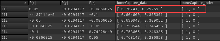
Unpacked boneCapture point array attributes
Unpacked boneCapture array attributes can be packed into index-pair attributes using the ![]() Capture Attribute Pack SOP.
Capture Attribute Pack SOP.
Modify capture weights with capture geometry shapes 
The ![]() Attach Joint Geometry SOP can be used to attach geometry to skeleton joints, with the geometry affecting the results of the capture weight creation in the
Attach Joint Geometry SOP can be used to attach geometry to skeleton joints, with the geometry affecting the results of the capture weight creation in the ![]() Joint Capture Biharmonic SOP downstream.
Joint Capture Biharmonic SOP downstream.
The process for creating geometry shapes to influence biharmonic capture is:
-
Create the capture geometry shapes.
-
Assign the capture geometry shapes to skeleton joints.
-
Apply the capture geometry shapes to the biharmonic capturing process.
The example in this file demonstrates the use of attaching geometry to joints to influence the result of biharmonic capturing.
Create capture geometry shapes 
In the network editor, create the capture geometry shapes at their world space positions inside the volume of the character. Only the capture geometry points inside the volume are considered for the biharmonic calculations. To modify the size or shape of the capture geometry, use SOP nodes like the ![]() Edit SOP or
Edit SOP or ![]() Transform SOP.
Transform SOP.
Warning
Only use polygonal geometry for the capture shapes. NURBS do not work properly.


The ![]() Merge Packed SOP,
Merge Packed SOP, create_capture_geo_library, merges the set of capture geometry to create a library of shapes. In the Merge Packed SOP:
-
The Name Primitive Attribute parameter is turned on by default. When an input is connected to the Merge Packed SOP, a Name parameter is automatically created and populated with the name of the input node. You can define new names for the capture geometry shapes by updating the Name parameters with meaningful names like
wrist_leftorhips_tilt. -
Turn on the Name Override Attribute parameter, which is set to the
nameattribute by default. When Name Override Attribute is turned on, the Merge Packed SOP sets the shape names to the value of thenameattribute present on the input geometry. If thenameattribute is not present, the Name parameter is used instead.
Warning
After you assign shapes to joints using the Attach Joint Geometry SOP downstream, do not click the Reload Node Names button on the Merge Packed SOP. This will invalidate all your shape-joint assignments by reverting the shapes' names to their defaults.
Assign capture geometry shapes to joints 
Use the Attach Joint Geometry SOP to assign the capture geometry shapes to skeleton joints. This links the shape to the joint, and designates the shape as the joint’s capture object:

In the Attach Joint Geometry SOP, set the Role parameter to Capture Geo so that the attached geometry is used to influence the result of the biharmonic capture.
To assign the capture geometry shapes to the character’s joints:
-
Select the Attach Joint Geometry SOP.
-
Click
Show Handle on the left toolbar, or hover over the viewport and press Enter. You are now in the Attach Joint Geometry viewer state. -
On the viewer state’s toolbar, select Mode ▸ Assign Shapes to set the interaction mode to shape assignment, and turn on Assign in World Space. The world space shapes appear in blue:

-
In the viewer state, click a joint on the skeleton, hold G, and click the shape you want to assign to the joint.
In the parameter editor, Add Shapes tab, a new Assign Shapes multiparm for the joint appears with the following parameters:
-
Group - The selected joint.
-
Shape Name - The capture geometry shape.
-
Keep Shape World Transform is turned on.
A blue ring appears around the joint indicating that it has a shape assigned to it. The capture geometry shape in the Shape Name parameter is now assigned to the joint in the Group parameter. The world space shape’s position (in world space and relative to the character) does not change.

Blue ring indicates the joint has an assigned shape You could also create a new Assign Shapes multiparm by either clicking the Create New Group button in the viewer state toolbar or manually adding the multiparm in the parameter editor.
-
Tip
If you want to remove a joint from a shape assignment, hold ⌃ Ctrl and click the joint in the viewer state.
Apply capture geometry shapes to capture process 
The Joint Capture Biharmonic SOP takes the updated skeleton with the capture geometry shapes assigned to joints, and creates capture weights on the character geometry. The character geometry is then deformed by the Joint Deform SOP:

On the Joint Capture Biharmonic SOP, create_capture_weights, the Capture Geo Role parameter is set to Capture Geo by default. This causes the capture geometry to influence the result of the biharmonic capture.
Mirror capture geometry shapes 
If capture geometry shapes have been assigned to one side of the skeleton, the ![]() Skeleton Mirror SOP can be used to mirror the shapes on the other side. The mirrored shapes are then transferred to the input skeleton using another Attach Joint Geometry SOP:
Skeleton Mirror SOP can be used to mirror the shapes on the other side. The mirrored shapes are then transferred to the input skeleton using another Attach Joint Geometry SOP:

keep_left_side_joints
This ![]() Delete Joints SOP deletes the joints from one side of the skeleton so that we can have a cleaner starting point in the subsequent mirroring step (when both the capture shapes and joints are mirrored). For example, if capture shapes were added to the left side of the skeleton, you would delete all the joints on the right side of the skeleton. In the subsequent Skeleton Mirror SOP, the joints and capture shapes, both on the left side of the skeleton, are mirrored back to the right side.
Delete Joints SOP deletes the joints from one side of the skeleton so that we can have a cleaner starting point in the subsequent mirroring step (when both the capture shapes and joints are mirrored). For example, if capture shapes were added to the left side of the skeleton, you would delete all the joints on the right side of the skeleton. In the subsequent Skeleton Mirror SOP, the joints and capture shapes, both on the left side of the skeleton, are mirrored back to the right side.
In the Group parameter, specify the set of joints you want to delete.
mirror_joints_and_capture_geo
This Skeleton Mirror SOP duplicates the points on the skeleton in a mirrored fashion. The output of the Skeleton Mirror SOP is a skeleton with joint shapes mirrored on both sides of the character.
Set the Find Tokens parameter to match the prefix or suffix of the skeleton joints. The mirrored joint names will have the original joint names with the prefix or suffix replaced with the Replace Tokens parameter. For example, if Find Tokens = L_ and Replace Tokens = R_, the mirrored joint of L_Arm is R_Arm.
transfer_mirrored_capture_geo
This Attach Joint Geometry SOP transfers the mirrored shapes to the skeleton.
In the Add Shapes tab, set Role to Capture Geo.
In the Shape Template tab, specify how to transfer the mirrored shapes to the skeleton:
-
Target Joints - Specify the skeleton joints to apply the new mirrored shapes to, for example,
@name=R_*. -
Template Joints - Specify the shapes to transfer to the skeleton, for example,
@name=R_*. -
Set Match By to Attribute Value. This matches the shapes in the capture geometry library to the skeleton joints based on the
nameattribute on the shapes and joints (thenameattribute is specified in the Attribute to Match parameter). -
Turn on Keep Template World Transform to use the world positions of the shapes.
Shape templates 
You can automatically assign shapes from the capture geometry library to skeleton joints using the Shape Template input (3rd input) of the Attach Joint Geometry SOP:

promote_prim_to_point
This ![]() Attribute Promote SOP converts the primitive
Attribute Promote SOP converts the primitive name attributes from the capture geometry library (create_capture_geo_library) to point attributes that the Attach Joint Geometry SOP accepts on its Shape Template input.
Set the following parameters:
-
Original Name =
name -
Original Class = Primitive
-
New Class = Point
-
Turn on Delete Original to delete the primitive
nameattributes since they are no longer needed.
attach_capture_geo_to_joints
In the Add Shapes tab, set Role to Capture Geo.
In the Shape Template tab, specify how to transfer the shapes in the shape template to the skeleton:
-
Target Joints - Specify the skeleton joints to apply the shape template to.
-
Template Joints - Specify the shapes to assign to the skeleton.
-
Set the Match By parameter to Attribute Value. This matches the shape template to the skeleton joints based on the
nameattribute on the shapes and joints (thenameattribute is specified in the Attribute to Match parameter). -
Turn on Keep Template World Transform to use the world positions of the shapes.
Paint capture weights 
The ![]() Joint Capture Paint SOP allows you to interactively paint capture weights on geometry. It can be used to create new capture weights or modify existing capture weights:
Joint Capture Paint SOP allows you to interactively paint capture weights on geometry. It can be used to create new capture weights or modify existing capture weights:

You can also add animation using a ![]() Rig Pose SOP and view the deformation while painting weights on the Joint Capture Point SOP:
Rig Pose SOP and view the deformation while painting weights on the Joint Capture Point SOP:

Associated nodes 
The following SOP nodes are used to create, edit, paint, and work with capture weights:
Node |
Description |
|---|---|
|
Attaches geometry to joints to influence the result of the biharmonic capture. This can be more efficient than purely joint position-based biharmonic capture (Joint Capture Biharmonic SOP) and weight painting (Joint Capture Paint SOP), as it gives you more control over influencing areas per joint. |
|
|
Takes a set of array attributes and uses a naming convention to convert them into a single index-pair attribute. |
|
|
Takes an index-pair attribute and uses a naming convention to convert it into a set of array attributes. |
|
|
Mirrors capture weights from one half of a character to the other half. |
|
|
Sets a joint to control an entire piece of geometry. This is mainly used for rigidly deformed parts of a character. |
|
|
Creates smoothed-out capture weights on geometry based on joint position and volume. The geometry is then deformed by the Joint Deform SOP. Works well for softer, non-mechanical, organic deformation. |
|
|
Allows you to interactively paint capture weights on geometry. |
|
|
Creates capture weights based on the geometry point’s distance to joints. This is a quicker and less computationally-intensive operation than the Joint Capture Biharmonic SOP, but results in weights that are not as evenly distributed or smoothed out, especially for organic surfaces. The Joint Capture Proximity SOP works well for rigging simple geometry like a tube. |
|
|
Works in conjunction with joint capture nodes (Joint Capture Biharmonic SOP, Joint Capture Proximity SOP, Joint Capture Paint SOP) to deform geometry. |