| On this page |
After retargeting animation and cleaning up your retarget results, you can tweak the imported animation or add some of your own animation on top of the source input by using the ![]()
![]() Rig Pose SOP node.
Rig Pose SOP node.
The Rig Pose SOP node allows you to pose your character, select and manipulate its joints, and key your poses.
Where you place the Rig Pose SOP in your retargeting network in relation to the ![]()
![]() Full Body IK SOP node and what Mode you use for each point’s transform is very important. This is because where you place the Rig Pose SOP node determines when any new keys are applied to your character’s existing animation and the Mode you choose for each point’s transform decides how those transformations are applied.
Full Body IK SOP node and what Mode you use for each point’s transform is very important. This is because where you place the Rig Pose SOP node determines when any new keys are applied to your character’s existing animation and the Mode you choose for each point’s transform decides how those transformations are applied.
Adding multiple Rig Pose SOP nodes to your network will create a layered animation effect. You can add Rig Pose SOPs to any location on the animated pose stream of your retargeting network, or on the source skeleton stream just before the Full Body IK SOP. How you layer your animation will affect the FBIK solve and change the network’s output animation.
Baking animation 
You can use a ![]() Rig Pose SOP node to bake down any animation in your retarget network to a series of animation channels. For example, you can bake down a single pose, the source animation for your retarget, or a series of IK keyframes.
Rig Pose SOP node to bake down any animation in your retarget network to a series of animation channels. For example, you can bake down a single pose, the source animation for your retarget, or a series of IK keyframes.
You can then open the baked animation channels in the Animation Editor to edit or delete their individual keyframes. This is very useful when you need to cull the dense keyframes from a motion capture animated source skeleton.
-
Select the Rig Pose SOP node that contains the keyframes you want to bake or the Rig Pose SOP that is downstream from the input animation you want to bake.
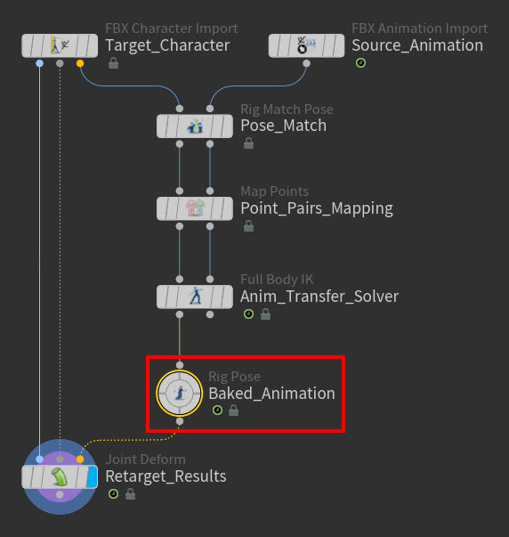
Example: Rig Pose SOP containing the source animation that has been run through the FBIK solve -
In the Parameter Editor, select the Pose tab and then click Bake.
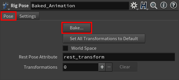
The Rig Pose Baking controls dialog window appears.
-
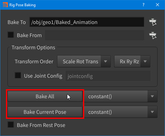
In the Rig Pose Baking controls dialog, select the bake settings you want to use for your animation and then click either Bake All or Bake Current Pose.
A Transformations multiparm Group appears in the node’s parameters for every animated transform in the Rig Pose SOP you selected, and each multiparm’s Mode is automatically set to Override.
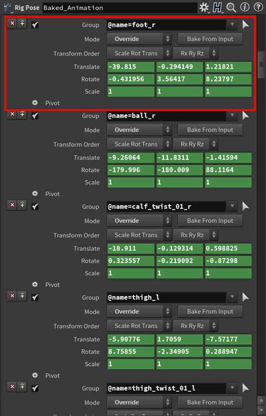
Example: Right Foot and the rest of the baked anim channels in the Parameter Editor -
Close the Rig Pose Baking controls dialog window.
-
Open the Animation Editor.
All the Rig Pose SOP’s animation channels and keyframes are loaded in the Animation Editor.
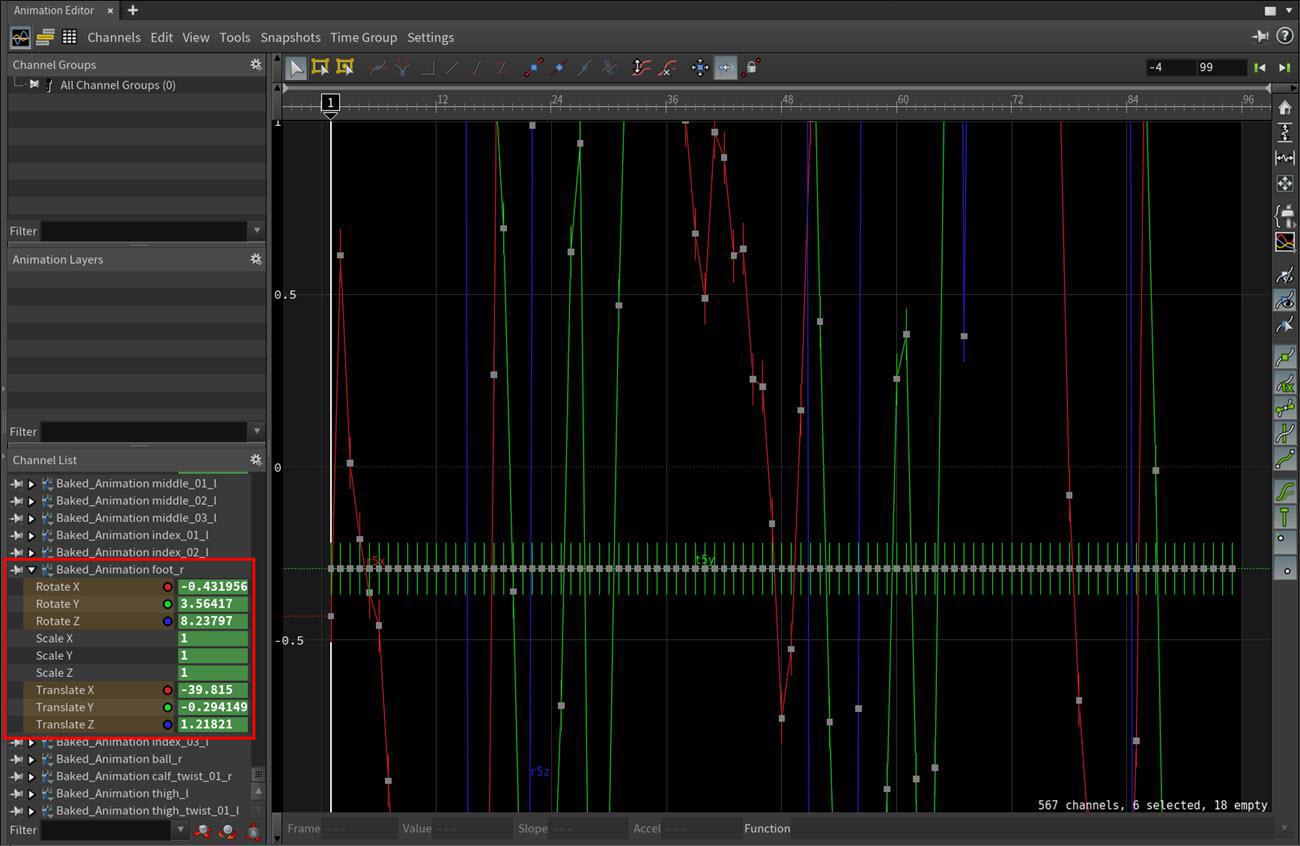
Example: Right Foot and the rest of the baked anim channels in the Animation Editor -
Edit the baked animation channels and keyframes as you desire.
Creating control shapes for posing 
Posing and animating retargeted skeletons and characters with FK 
You can pose and animate individual joint transforms in your retarget with a ![]() Rig Pose SOP. This is useful when you need to make little pose tweaks to avoid intersections of geometry or you want to make small animation additions that do not require an IK chain.
Rig Pose SOP. This is useful when you need to make little pose tweaks to avoid intersections of geometry or you want to make small animation additions that do not require an IK chain.
-
In the Node Editor, create a
 Rig Pose SOP node.
 -
Place the Rig Pose SOP node on the deformed point transforms stream of your retargeting network based on when you want it’s influence to be applied.
-
If you want the Rig Pose SOP node’s pose or keyframes to be applied before the FBIK solve, then place it on the source skeleton stream before the Full Body IK SOP. This way the Rig Pose SOP node’s pose or keyframes will be run through the FBIK solve.
-
If you want the Rig Pose SOP node’s pose or keyframes to be applied after the FBIK solve, then place it on the target skeleton stream after the Full Body IK SOP. This way Rig Pose SOP node’s pose or keyframes will not be run through the FBIK solve. This is the typical placement location.
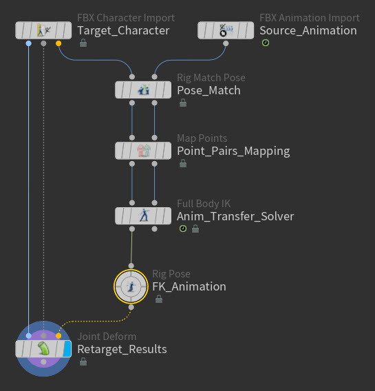
Example: Rig Pose SOP at the end of a retarget network -
-
Turn on the Display flag for the Joint Deform SOP and then select the Rig Pose SOP node.
-
Click in the viewport and then press Enter.
You are now in the Rig Pose interaction state.
In this state, you now have access to the Rig Pose toolbar and
 pop-up menu.
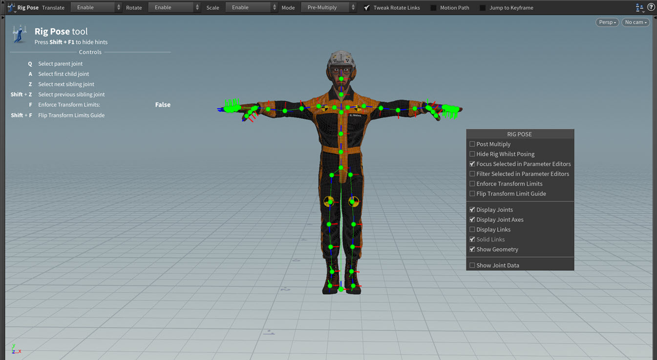
Example: Rig Pose state -
For each joint that you want to pose or animate, select the joint or its control geometry and then use the joint’s manipulator handles to pose it and the K hotkey to key it until you have created the animation you are looking for.
When you select a joint, a Transformations multiparm Group is automatically created for it. This multiparm stores all the transform data for that joint.
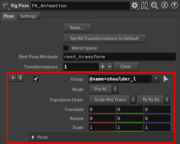
Example: Transformations multiparm If you transform a joint without placing a key, then you will change that joint’s pose for its skeleton or character’s entire animation.
If you transform a joint and key its various poses, then you will animate that joint using FK.
When you are manipulating the joints in your skeleton or character, please switch the Modes as needed. Depending on which Mode you select, your modifications to the joint’s transforms will be applied:
-
In parent space (Post-Multiply), changing the joint’s offsets from its parent.
-
In local space (Pre-Multiply & From Rest Pose), layering the joint’s transforms on top of the input animation.
-
As a replacement (Override), completely overriding any input animation.
Example: Manipulating joints and setting FK keys -
Posing and animating retargeted skeletons and characters with IK 
You can pose and animate 3-joint triplets in your retarget with IK by using an ![]()
![]() IK Chains SOP node with a
IK Chains SOP node with a ![]() Rig Pose SOP node. This is useful when you need to make pose tweaks to elbows or knees that are not bending quite right or you need to add some gestural animation to your target skeleton or character’s limbs.
Rig Pose SOP node. This is useful when you need to make pose tweaks to elbows or knees that are not bending quite right or you need to add some gestural animation to your target skeleton or character’s limbs.
-
Create the geometry that will drive the IK.
In KineFX, you can’t apply an IK Chains SOP directly to the geometry that it will be driving. Instead, you need to use separate driver geometry, either created from scratch or created by using a subset of the skeleton geometry it is intended to manipulate. A powerful feature of the second approach is that incoming animation will be inherited by these IK controls.
-
Create a
 Delete Joints SOP.
 -
Connect the target skeleton output (output 2) from the
 Full Body IK SOP node to the input of the Delete Joints SOP.
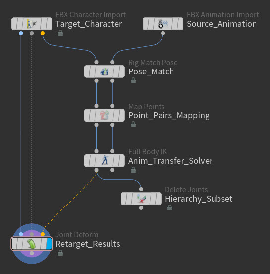
Example: Delete Joints SOP node in the network -
Select the Delete Joints SOP and in the Parameter Editor, select the arrow icon next to the Group field and in the viewport, use that selection tool to select the three joints you want to drive with the IK chain, and then press Enter.
The selected joints appear in the Group field.
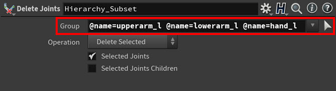
Example: Joints listed in the Group parameter field -
Select Delete Non-Selected from the Operation drop-down menu.
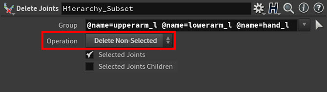
Example: Delete Points SOP node’s Delete Non-Selected parameter
You now have three new driver points that will act as your IK chain’s handle. Since you just thinned out part of the original hierarchy, the names of the three points correspond to the joints they will be driving.
-
-
Create a Rig Pose SOP, and then connect the output from the Delete Joints SOP to the input from the Rig Pose SOP.
This Rig Pose SOP will allow you to select, pose, and key the IK chain.
-
Create a IK Chains SOP, and then do the following:
-
Connect the target skeleton output (output 1) from the Full Body IK SOP node to the input of the IK Chains SOP node.
-
Connect the output from the Rig Pose SOP to the input of the IK Chains SOP node.
-
Connect the output from the IK Chains SOP node to the deform point input (input 3) on the Joint Deform SOP.
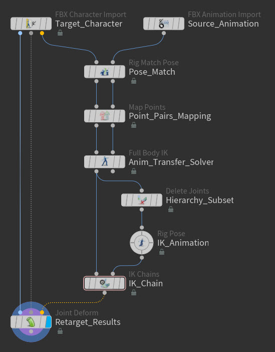
Example: IK Chains node in the network -
-
Select the IK Chains SOP node.
-
In the Parameter Editor, do the following:
-
For the Root Name parameter, select the arrow icon next to its field, in the viewport use that selection tool to select the joint where the IK chain will begin, and then press Enter.
-
For the Mid Name parameter, select the arrow icon next to its field, in the viewport use that selection tool to select the middle joint for IK chain, and then press Enter.
-
For the Tip Name parameter, select the arrow icon next to its field, in the viewport use that selection tool to select the joint where the IK chain will end, and then press Enter.
-
Turn on the Match by Name parameter.
Since the subset geometry you created with the Delete Joints SOP has the same names of the joints they will be driving with the IK, this option automatically matches the subset geometry to the hierarchy points they will drive.
-
Set the Blend parameter to 1.
The IK chain is now active.
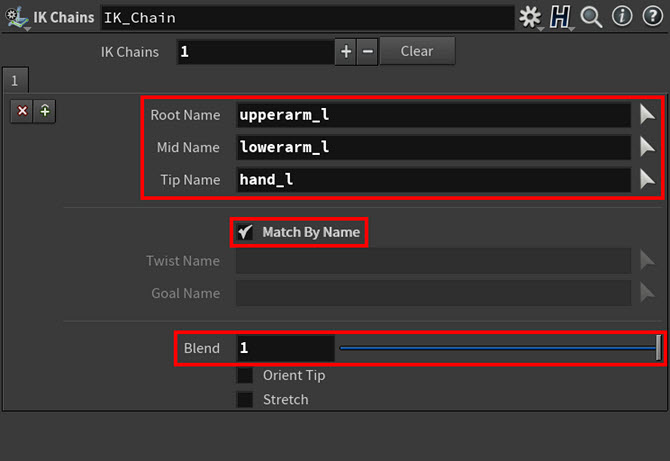
Example: IK Chains SOP node parameter settings 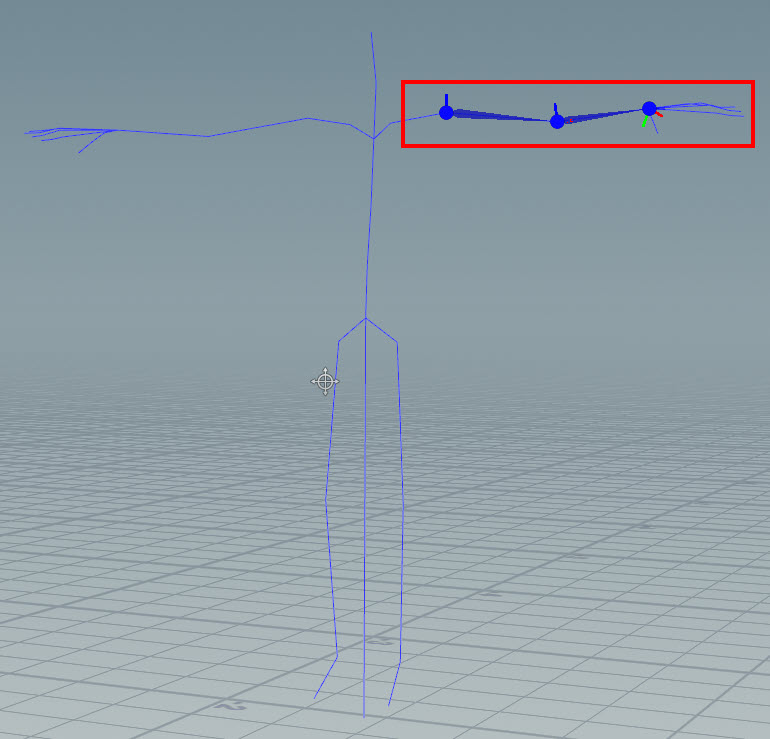
Example: IK Chain in the viewport
-
-
Turn on the Display flag for the Joint Deform SOP and select the Rig Pose SOP node.
-
You can now select, manipulate, and key the IK chain driver points in the viewport.
When you select an IK driver point, a Transformations multiparm Group is automatically created for its driven joint. This multiparm stores all the transform data for that IK driver’s joint.
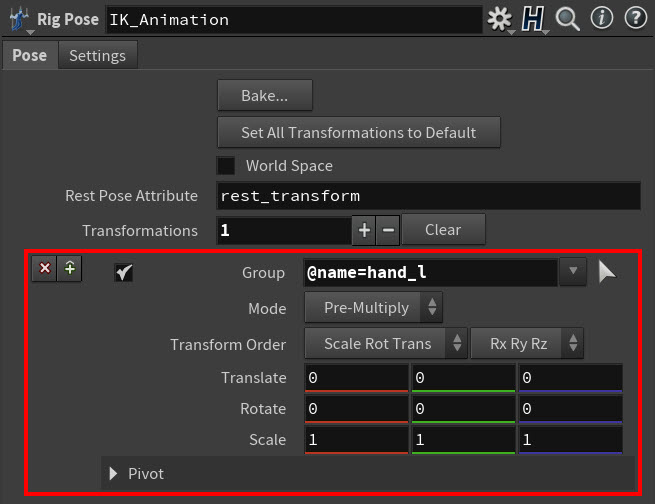
Example: Transformations multiparm If you transform the IK chain driver points without placing a key, then you will change their joints' poses for their skeleton or character’s entire animation.
If you transform an IK chain driver point and key its various poses, then you will animate its driven joint using IK.
When you are manipulating your skeleton or character’s IK chain driver points, please switch the Modes as needed. Depending on which Mode you select, your modifications to all the driven joint transforms will be applied:
-
In parent space (Post-Multiply), changing the joint’s offsets from its parent.
-
In local space (Pre-Multiply & From Rest Pose), layering the joint’s transforms on top of the input animation.
-
As a replacement (Override), completely overriding any input animation.
-
Mirroring poses or animation 
You can mirror the animation inside a retargeting operation by using the ![]()
![]() Rig Mirror Pose SOP node.
Rig Mirror Pose SOP node.
You can predictably mirror your animation at three possible points in your retarget network:
-
Just after the source input (the input animation), but before the retarget operation.
-
After the FBIK solve, but before any FK or IK poses and keys.
-
At the end of your network, but before the Joint Deform SOP.
There are multiple parameter setting combinations you could use for the Rig Mirror Pose SOP, but the following process has consistently proven to generate good results.
-
In the Node Editor, make sure that your source KineFX import node is set to it’s first frame, and then create a Rig Mirror Pose SOP node and a
 Rig Stash Pose SOP node.
 -
Do the following:
-
Connect the output from the source KineFX import node to the rig input (input 1) on the Rig Stash Pose SOP node.
-
Connect the rig output (output 1) from the Rig Stash Pose SOP node to input on the Rig Mirror Pose SOP.
-
Connect the output from the Rig Mirror Pose SOP node to the source skeleton input (input 2) on the
 Rig Match Pose SOP node.
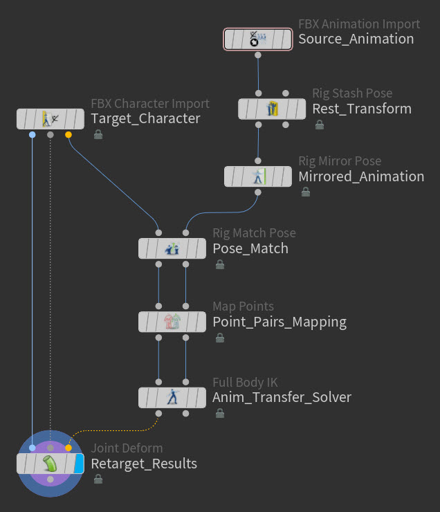
Example: Rig Mirror Pose in the network
-
-
In Parameter Editor, select the Rig Stash Pose SOP node and look at its parameters.
You will see a
rest_transformattribute in the Attribute Name field. This rest pose will help the Rig Mirror Pose SOP fix any flipped axes and generate good joint orientations in the mirrored animation.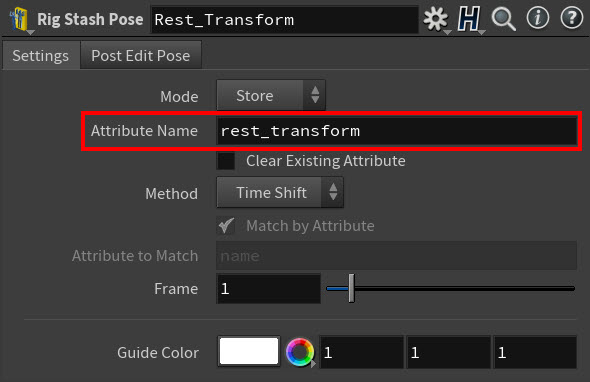
Example: Rig Stash Pose parameters -
In the Node Editor, select the Rig Mirror Pose SOP.
-
In Parameter Editor, expand the Compute Mirroring Options section.
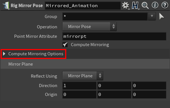
Example: Compute Mirroring Options section -
In the Compute Mirroring Options section, set Rest Pose Source to Attribute and make sure that Compute Flip Axes From is set to Rest Pose.
The Rest Pose Attribute field auto fills with the
rest_transfromattribute you created with the Rig Stash Pose SOP node.With this rest pose, the Rig Mirror Pose SOP will be able to automatically compute and fix any flipped axes and produce good joint orientations in the mirrored animation.
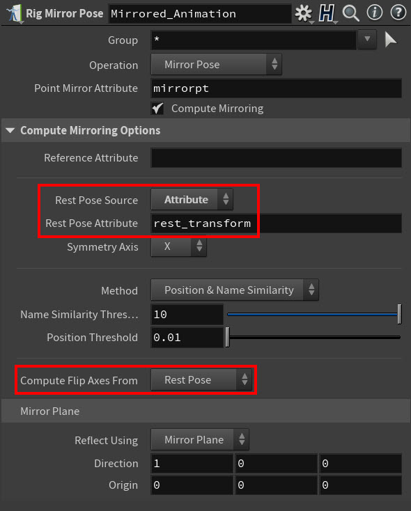
Example: Rest pose-related Rig Mirror Pose parameter settings -
Go to the viewport.
You can now see the mirrored animation in the viewport. All the skeleton joints that were successfully mirrored are highlighted in red.
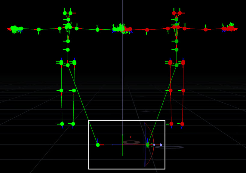
Example: Mirrored skeletons and the mirror plane manipulator -
Select the mirror plane manipulator and drag it until each skeleton is on one side of the mirror plane.
-
Playback your animation to view the results of the mirror pose operation.
Example: Mirrored animation pose