| On this page |
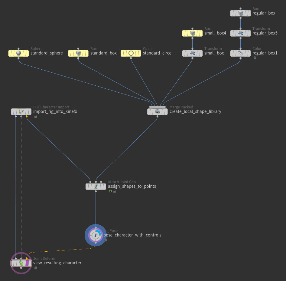
Control objects or shapes are named packed or unpacked primitives created in local space or world space that you can assign to the joints (points) in your KineFX skeleton using the ![]()
![]() Attach Joint Geometry SOP node.
Attach Joint Geometry SOP node.
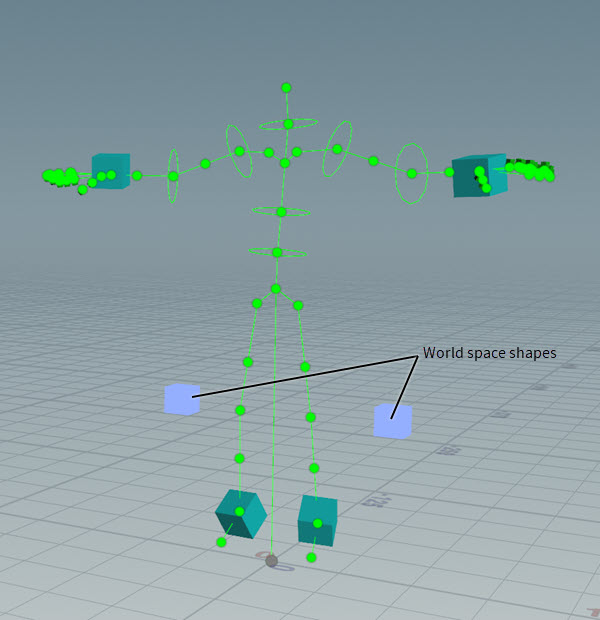
When a control is a local space shape, it means that it was modeled at the scene origin and it will be automatically moved to the local space of its target point when it is assigned. When a control is a world space shape, it means that it was modeled in-context at its correct position in world space near its target point and its position will not change when it is assigned.
Once you have assigned control shapes to your joints, you can use the controls as selectors for those joints. These controls make it easier to select your skeleton’s joints when posing your character with the ![]()
![]() Rig Pose SOP node.
Rig Pose SOP node.
Important Note
We strongly recommend that your character have a rest pose (default attribute: rest_transform). The rest pose can come in on your imported character, or you can create one for it using a ![]()
![]() Rig Stash Pose SOP node. A rest pose is needed to produce optimal control shape viewport state behavior and performance, especially when assigning control shapes in world space.
Rig Stash Pose SOP node. A rest pose is needed to produce optimal control shape viewport state behavior and performance, especially when assigning control shapes in world space.
Shape libraries 
Creating local space control shapes 
-
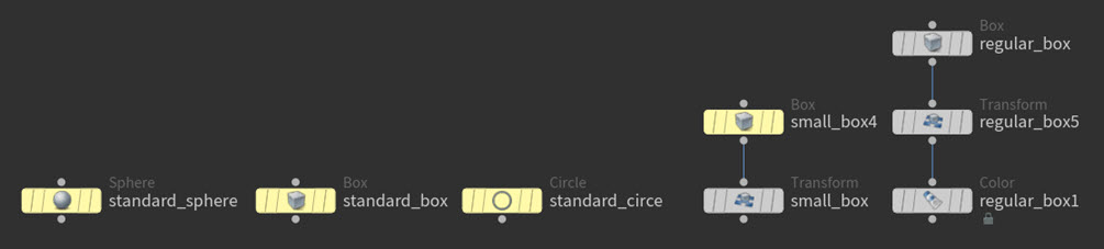
In the Network Editor, create unpacked or packed primitive geometry objects at the scene origin. These will be your local space control shapes.
Warning
Only use polygons primitives for your control shapes. Nurbs will not work properly.
-
If you want to change the shape or size of the local space shapes you created, then use common SOP nodes like the
 Edit SOP or the
  Transform SOP to modify them.
 -
If you want to define a custom color for your control shapes, then use a
 Color SOP node for each shape.
Note
On the Color SOP node, be sure to set the Class parameter to Primitive.
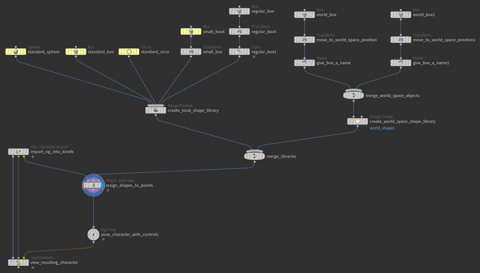
Creating a local space shape library 
A local space shape library should contain all the shapes that you want to assign locally to your joints.
-
Once you have created all the local space shapes you want to use as control shapes, create a
 Merge Packed SOP node.
 -
Connect all the local space shapes to the Merge Packed SOP node.
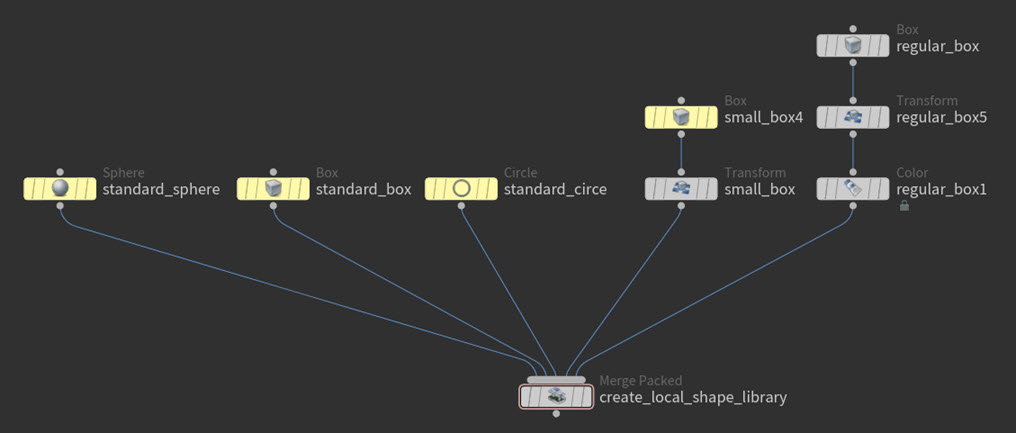
Example: Local space objects connected to the Merge Packed SOP node Note
Older control shape set-ups that use a
 Merge SOP node instead of the Merge Packed SOP to combine the shapes will still work with the Attach Joint Geometry SOP node.
 -
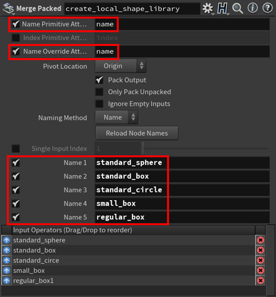
In the Merge Packed SOP node’s parameters, do the following:
-
Turn on the Name Primitive Attribute and Name Override Attribute parameters. This will allow you to define new names for your local space shapes.
-
Use the Name parameters to specify meaningful names for all the local space shapes. For example,
wrist_leftorhips_tilt. We recommend that you always name your shapes properly as it will make them much easier to identify in the future.
Warning
After you have assigned your shapes in the Attach Joint Geometry SOP node, do not click the Reload Node Names button on the Merge Packed SOP node as this will invalidate all your shape-joint assignments by reverting all the control shapes' names to their defaults.
-
-
When you are happy with your local space shapes library, create the
 Attach Joint Geometry SOP node.
 -
Connect the animated pose output from your character’s import node to the first input on the Attach Joint Geometry SOP, and then connect the Merge Packed SOP node’s output to the second input (shape library input) on the Attach Joint Geometry SOP node.
-
Do one of the following:
-
If your imported character is not animated:
-
On the character’s import node, remove the expression (if one exists) from the Timing ▸ Time parameter field. This will prevent the node from needlessly recooking.
-
(Optional) On the Attach Joint Geometry SOP node, turn off the Add Shapes ▸ Rest Pose Attribute parameter.
-
-
If your imported character is animated:
-
When the character does not already have a rest pose, use a
 Rig Stash Pose SOP node to create one for it, insert a
  Rig Doctor SOP node just after the Rig Stash Pose SOP node in the graph, and then type
 rest_transforminto the Freeze Time Dependent Attributes ▸ Attributes to Freeze parameter field on the Rig Doctor SOP node. This will prevent the node from needlessly recooking. -
When the character already has a rest pose, make sure that the Add Shapes ▸ Rest Pose Attribute parameter on the Attach Joint Geometry SOP node is turned on.
-
-
-
(Optional) Store the shape library as a standard you can reuse later.
Do the following
-
Connect the Merge Packed SOP node’s output to a
 ROP Geometry Output SOP node.
 -
Use the ROP Geometry Output SOP node to save the library to disk.
-
Then whenever you want to use the shape library for a character, load the stored geometry library with a
 File SOP node and then connect the File SOP node’s output to the second input on the Attach Joint Geometry SOP node.
-
You can now start assigning your local space shapes to your character’s joints.
Creating world space control shapes 
-
In the Network Editor, model the geometry objects that you want to use as control shapes in-context at their world space positions near the character.
This is a convenient way to model complex controls shapes to match the outline of your character since you do not need to model them with an offset.
Warning
Only use polygonal geometry for your control shapes. Nurbs will not work properly.
-
If you want to change the shape or size of the world space shapes you created, then use common SOP nodes like the
Edit SOP or the Transform SOP to modify them. -
If you want to choose a custom color for your control shapes, then use a
Color SOP node for each world space shape.Note
On the Color SOP node, be sure to set the Class parameter to Primitive.
-
Create a
 Name SOP node for each world space shape and then use their Name parameters to specify meaningful names for the objects. For example,
 wrist_leftorhips_tilt. We recommend that you always name your shapes properly as it will make them much easier to identify in the future.
Tip
If you did not name your control shapes, you can turn on Create Missing Names by Connectivity parameter on the ![]()
![]() Attach Joint Geometry SOP node. All the missing names for your world space control shapes will then be automatically created based on their shape connectivity. However, be careful with this option as changing the number of unnamed input shapes will affect the naming of any already assigned shapes.
Attach Joint Geometry SOP node. All the missing names for your world space control shapes will then be automatically created based on their shape connectivity. However, be careful with this option as changing the number of unnamed input shapes will affect the naming of any already assigned shapes.
Creating a world space shape library 
A world space shape library should contain all the shapes that you want to assign to your joints but keep them at their world space offsets.
-
Once you have created all the world space shapes you want to use as controls and have also assigned them names (
nameattribute), create a Merge SOP node. -
Connect all the world space control shape’s Name SOP nodes to the Merge SOP node.
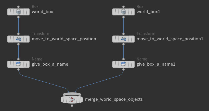
Example: World space control shapes connected to the Merge SOP node -
Create a
Group Create SOP node and connect the Merge SOP to its first input. This will be your world space shape library. -
In the Group Create SOP node’s parameters, set the Group Name to
world_shapesand the Group Type to Primitives.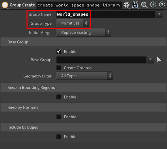
Example: Group Create SOP node parameters 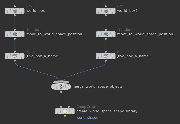
Example: Merge SOP node connected to the Group Create SOP node -
When you are happy with your world space shapes library, create the
Attach Joint Geometry SOP node. -
Connect the animated pose output from your character’s import node to the first input on the Attach Joint Geometry SOP, and then connect the Group Create SOP node’s output to the second input (shape library input) on the Attach Joint Geometry SOP node.
-
Do one of the following:
-
If your imported character is not animated:
-
On the character’s import node, remove the expression (if one exists) from the Timing ▸ Time parameter field. This will prevent the node from needlessly recooking.
-
(Optional) On the Attach Joint Geometry SOP node, turn off the Add Shapes ▸ Rest Pose Attribute parameter.
-
-
If your imported character is animated:
-
When the character does not already have a rest pose, use a
Rig Stash Pose SOP node to create one for it, insert a Rig Doctor SOP node just after the Rig Stash Pose SOP node in the graph, and then type rest_transforminto the Freeze Time Dependent Attributes ▸ Attributes to Freeze parameter field on the Rig Doctor SOP node. This will prevent the node from needlessly recooking. -
When the character already has a rest pose, make sure that the Add Shapes ▸ Rest Pose Attribute parameter on the Attach Joint Geometry SOP node is turned on.
-
-
-
In the Attach Joint Geometry SOP parameters, turn on the Has Input World Space Shape Group parameter in the Add Shapes ▸ Advanced Shape Settings settings section and then make sure that its Group parameter is set to
world_shapes. This ensures that your world space shapes will be visible and selectable in the viewport state when Assign in World Space is turned on in the viewport state’s toolbar.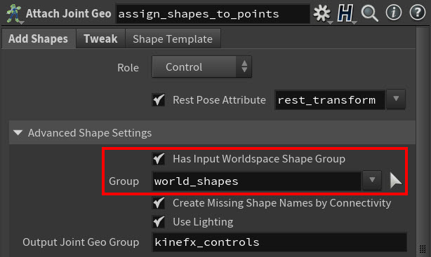
Example: Has Input World Space Shape Group = on and Group = world_shapes -
(Optional) Store this library as a standard you can reuse later.
Do the following
-
Connect the Merge Packed SOP node’s output to a
ROP Geometry Output SOP node. -
Use the ROP Geometry Output SOP node to save the library to disk.
-
Then whenever you want to use the shape library for a character, load the stored geometry library using a
File SOP node and use the File SOP node’s output directly as the local shape library.
-
You can now start assigning your world space shapes to your character’s joints.
Combining local space and world space shape libraries as a single input 
If you want to use both local space controls shapes and world space control shapes with your character, then you can merge your control object inputs into a single input.
-
Create a
Merge SOP node. -
Connect the output of the world space shape library (the
Group Create SOP node) to the Merge SOP node. -
Connect the output of the local space shape library (the
Merge Packed SOP node) to the Merge SOP node.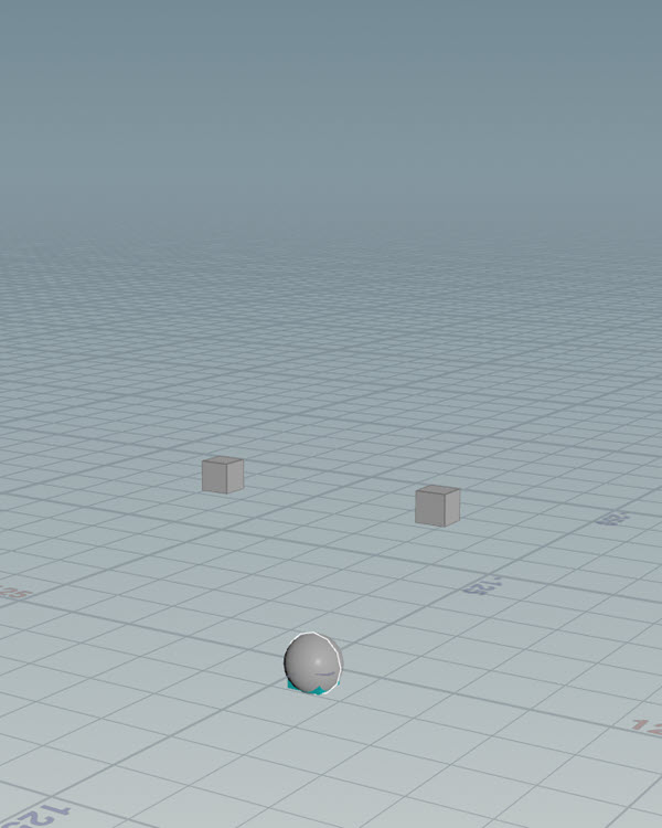
Example: Merged local space and world space shape libraries -
Create the
Attach Joint Geometry SOP node. -
Connect the animated pose output from your character’s import node to the first input on the Attach Joint Geometry SOP, and then connect the Merge SOP node’s output to the second input (shape library input) on the Attach Joint Geometry SOP node.
Example: Merged local space and world space shape libraries -
Do one of the following:
-
If your imported character is not animated:
-
On the character’s import node, remove the expression (if one exists) from the Timing ▸ Time parameter field. This will prevent the node from needlessly recooking.
-
(Optional) On the Attach Joint Geometry SOP node, turn off the Add Shapes ▸ Rest Pose Attribute parameter.
-
-
If your imported character is animated:
-
When the character does not already have a rest pose, use a
Rig Stash Pose SOP node to create one for it, insert a Rig Doctor SOP node just after the Rig Stash Pose SOP node in the graph, and then type rest_transforminto the Freeze Time Dependent Attributes ▸ Attributes to Freeze parameter field on the Rig Doctor SOP node. This will prevent the node from needlessly recooking. -
When the character already has a rest pose, make sure that the Add Shapes ▸ Rest Pose Attribute parameter on the Attach Joint Geometry SOP node is turned on.
-
-
-
In the Attach Joint Geometry SOP parameters, turn on the Has Input World Space Shape Group parameter in the Add Shapes ▸ Advanced Shape Settings settings section and then make sure that its Group parameter is set to
world_shapes. This ensures that your world space shapes will be visible and selectable in the viewport state when Assign in World Space is turned on in the viewport state’s toolbar.
Example: Has Input World Space Shape Group = on and Group = world_shapes
You can now start assigning your local space shapes and world space shapes to your character’s joints.
Assigning a local space control shape to a joint 
You can assign a local space shape to a joint in your input skeleton to link it to the joint and designate the shape as the joint’s new control object.
-
Select the
Attach Joint Geometry SOP node, click in the viewport, and then press Enter. You are now in the viewport state. -
In the viewport state’s toolbar, select Mode ▸ Assign Shapes to set the interaction mode to shape assignment.

Assign Shapes mode in the Attach Joint Geometry viewport state toolbar -
Click the joint in your skeleton that you want to assign the local space shape to as a control and then press G.
Tip
You can also add more than one joint to the same Assign Shapes multiparm by ⇧ Shift +
 -clicking them to include them all in your selection when you are creating the multiparm.
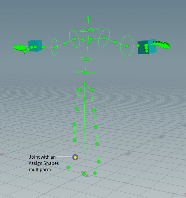
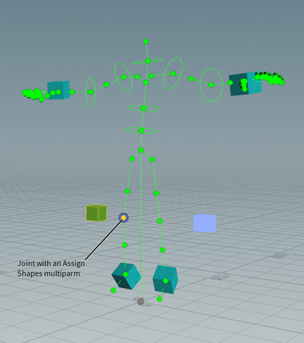
In the Parameter Editor, a new Assign Shapes multiparm for the joint appears in the Add Shapes tab and the name of the joint you selected appears in the Group field.
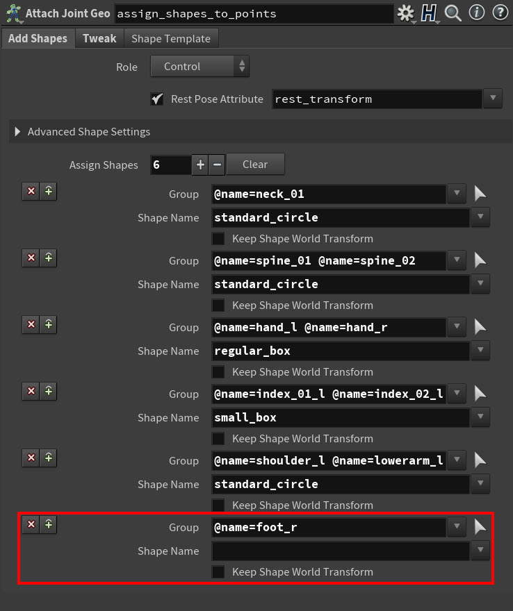
New Assign Shapes multiparm And a blue ring also appears around the joint indicating that it now has an active Assign Shapes multiparm.
Blue ring that indicates the joint has an Assign Shapes multiparm Tip
Alternatively, you can also create a new Assign Shapes multiparm by either clicking the Create New Group button in the viewport state toolbar or manually adding the multiparm in the Parameter Editor.
-
In the viewport state, use your
 to scroll through the local shape library in the mulitparm’s Shape Name field, stop at the name of the shape that you want to assign as the control for the joint you selected, and then -click in the viewport to confirm your selection.
Example: Scrolling through the local shape library The local space shape you selected in the Shape Name parameter field is now assigned as the control for the joint listed in the Group field.
The local space shape is also automatically moved from the scene origin to its target joint’s local space location.
Tip
-
If you ever need to remove a joint from a shape assignment, ⌃ Ctrl -
click the joint in the viewport state. -
If you ever need to re-assign a joint to a new multiparm, you can select the joint and press G again. The joint will automatically be removed from its old multiparm and will be added to a new one.
Assigning a world space control shape to a joint 
You can assign a world space shape to a joint in your input skeleton to link it to the joint and designate the shape as the joint’s new control object.
-
Select the
Attach Joint Geometry SOP node, click in the viewport, and then press Enter. You are now in the viewport state. -
In the viewport state’s toolbar, select Mode ▸ Assign Shapes to set the interaction mode to shape assignment and then turn on Assign in World Space.

Assign Shapes and Assign in World Space modes and in the Attach Joint Geometry viewport state toolbar The world space shapes appear as light blue in the viewport state.
-
In the viewport state, click the joint in your skeleton that you want to assign the world space shape to as a control, press-hold G, and then
-click the world space shape that you want to assign to the joint.Example: Assigning the world space shape in the viewport state In the Parameter Editor, a new Assign Shapes multiparm for the joint appears in the Add Shapes parameters tab.
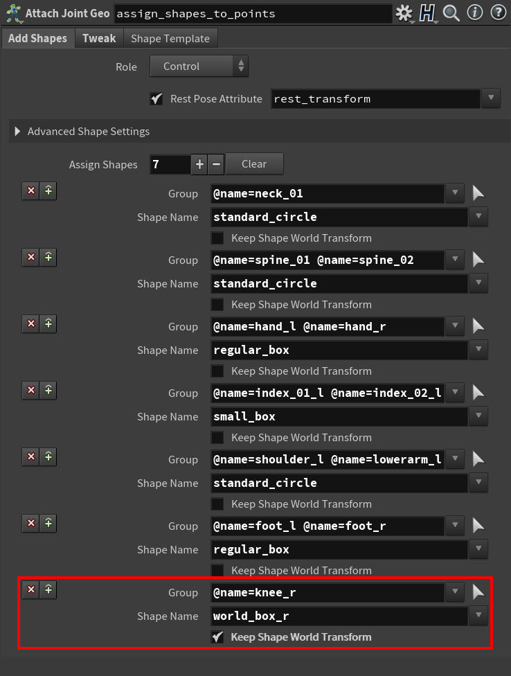
In the Assign Shapes multiparm, the joint you selected appears in its Group field, the world space shape you clicked appears in the Shape Name field, and the Keep Shape World Transform parameter is turned on.
New Assign Shapes multiparm for a world space shape And a blue ring also appears around the joint indicating that it now has an active Assign Shapes multiparm.
Blue ring that indicates the joint has an Assign Shapes multiparm Tip
Alternatively, you can also create a new Assign Shapes multiparm by either clicking the Create New Group button in the viewport state toolbar or manually adding the multiparm in the Parameter Editor.
The world space shape you selected in the Shape Name parameter field is now assigned as the control for the joint listed in the Group field.
The world space shape’s position (in world space and relative to your character) does not change.
Tip
-
If you ever need to remove a joint from a shape assignment, ⌃ Ctrl -
click the joint in the viewport state. -
If you ever need to re-assign a joint to a new multiparm, you can select the joint and press G again. The joint will automatically be removed from its old multiparm and will be added to a new one.
Tweaks 
Tweaks are transform offsets that you can apply to your input joints that the control shapes (local space or world space) assigned to them will then inherit. Tweaks are useful when you want to change the offsets or color of control shapes that were supplied by a shape template and/or an offset attribute.
Creating a tweak 
-
Select the
Attach Joint Geometry SOP node. -
In the Parameter Editor, select its Tweak tab.
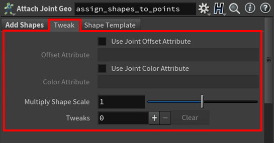
Tweak parameters tab All the parameters that let you define tweaks for your control objects live in this tab.
-
Click in the viewport and then press Enter. You are now in the viewport state.
-
In the viewport state’s toolbar, select Mode > Tweak Shapes to set the interaction mode to tweak creation and then select an Offset Mode to determine how the tweak to the control shape will behave in relation to any the other offset values supplied by a shape template and/or an offset attribute.

Attach Joint Geometry SOP viewport state’s Tweak mode toolbar -
Click the joint in your skeleton that you want to apply the tweak to and then press G.
In the Parameter Editor, a new Tweaks multiparm for the joint appears in the Tweak parameters tab and the name of the joint you selected appears in its Group field.
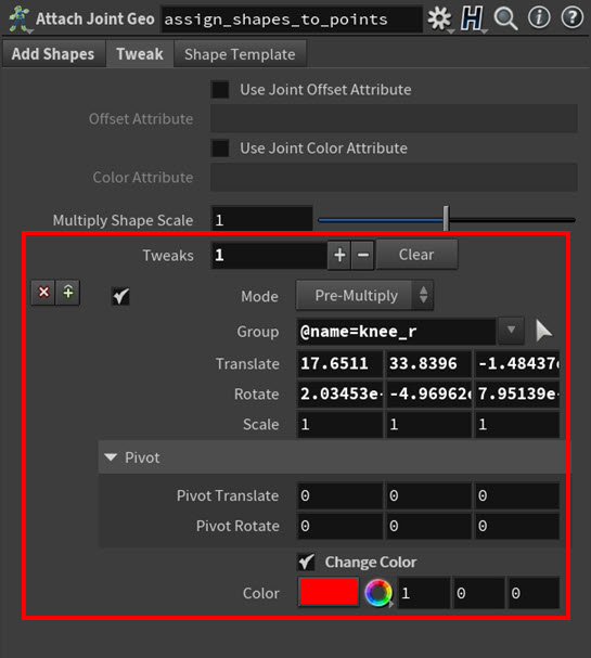
Tweak multiparm And a green ring appears around the joint indicating that it now has an active Tweaks multiparm.
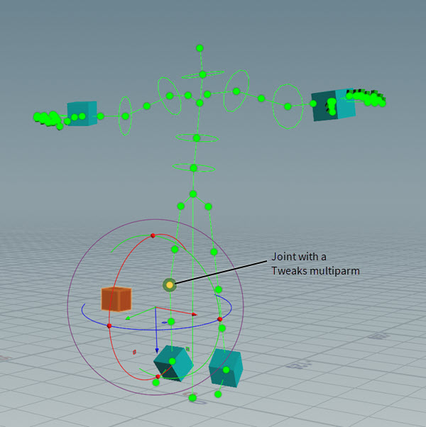
Joint with an active Tweaks multiparm Tip
If you want to remove a tweak from a joint, select the joint in the viewport state and then press ⌃ Ctrl + G.
-
Adjust the Tweaks multiparm’s settings from the viewport state using the tweak’s transform handle or from the Parameter Editor by adjusting its parameter values.
Note
You can only set the Color tweak parameter from the Parameter Editor.
Shape templates 
You usually do not want to create and assign your control shapes from scratch every time you build a character. In order to avoid that situation, you can use shape templates to export and import shape assignments and tweaks. And in addition to the template, you can always apply additional shape assignment and tweak changes on top of the shape template in the same ![]()
![]() Attach Joint Geometry SOP node.
Attach Joint Geometry SOP node.
Creating a shape template 
Once you have finished setting up your local space shape library, world space shape library, or your combined local and world shape libraries, you can then export your shape library as a shape template.
-
Create a
ROP Geometry Output SOP node and connect its input to the output of your shape library’s Attach Joint Geometry SOP node.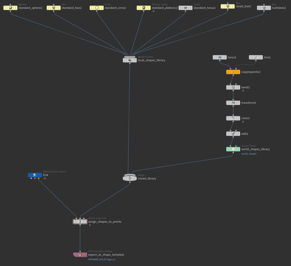
Example: Exporting the shape template network 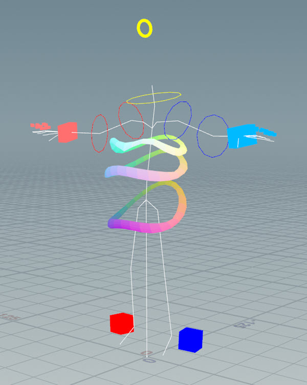
Example: What is being saved to the shape template -
In the ROP Geometry Output SOP node, set the Output File path to the network location where you want to save the
.bgeoshape library to. -
Click Save to Disk.
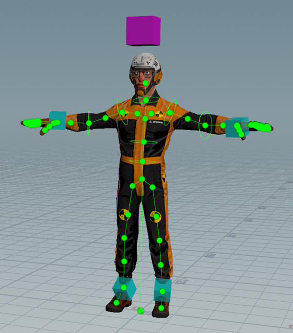
The output of the Attach Joint Geometry SOP node with the complete skeleton is saved to disk as a
.bgeoshape template file.A shape template contains points with packed primitives that have a point attribute for matching and optionally have metadata for offsets stored on the
jointgeoprimitive attribute.
Using a shape template 
-
Create a File SOP node and use its Geometry File parameter to load the shape template you want to use with your character.
-
Create a
Attach Joint Geometry SOP node and then do the following:-
Connect the third output from your character’s import node to the first input on the Attach Joint Geometry SOP,
-
Connect the output from the File SOP node to the third input on the Attach Joint Geometry SOP node.

Example: Importing and using the shape template network 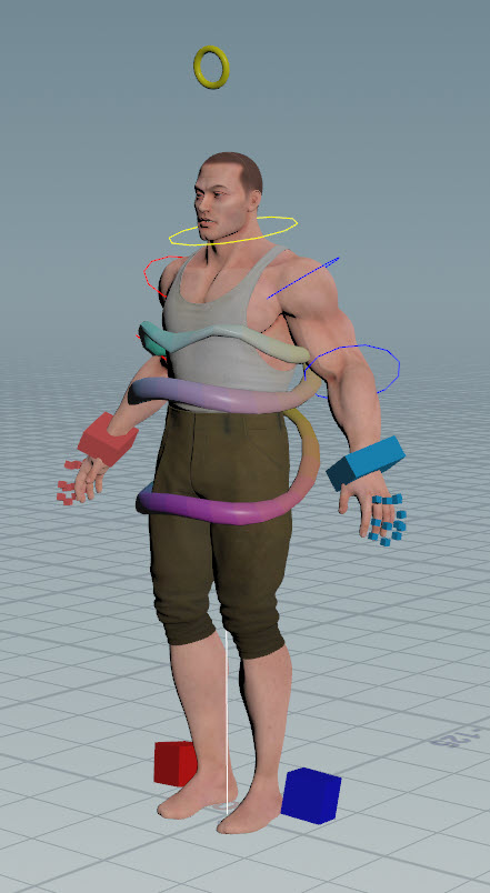
Example: Tommy using of the shape template that came from Erik -
-
Do one of the following:
-
If your imported character is not animated:
-
On the character’s import node, remove the expression (if one exists) from the Timing ▸ Time parameter field. This will prevent the node from needlessly recooking.
-
(Optional) On the Attach Joint Geometry SOP node, turn off the Add Shapes ▸ Rest Pose Attribute parameter.
-
-
If your imported character is animated:
-
When the character does not already have a rest pose, use a
Rig Stash Pose SOP node to create one for it, insert a Rig Doctor SOP node just after the Rig Stash Pose SOP node in the graph, and then type rest_transforminto the Freeze Time Dependent Attributes ▸ Attributes to Freeze parameter field on the Rig Doctor SOP node. This will prevent the node from needlessly recooking. -
When the character already has a rest pose, make sure that the Add Shapes ▸ Rest Pose Attribute parameter on the Attach Joint Geometry SOP node is turned on.
-
-
-
Select the Attach Joint Geometry SOP node.
-
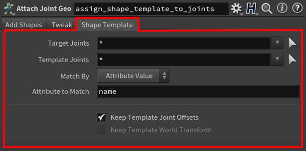
In the Parameter Editor, select the Shape Template tab and then use its parameters to configure how the shape template is transferred to your character and how its shapes are matched to its joints.
Shape Template tab parameters -
Use the Target Joints parameter to determine which joints will get a template assignment.
-
Use the Template Joints parameter to determine which control shapes will get assigned to the skeleton.
-
Use the Match By parameters to determine how to match the shape template to your skeleton.
-
Use Attribute Value (the default setting) when you want to match based on point attribute values on the skeleton and the shape template.
-
Use Point Value when you want to match based on point number values from the skeleton and the shape template.
Warning
If you use Point Number, be aware that the point numbers of your joints will change if you add or remove any joints from your skeleton. So be careful when you use this option.
-
Use Mapping Attribute when you want to match using a dictionary attribute. This is incredibly useful since you can use this Match By parameter to map your template to a differently named skeleton or to mirror a supplied template.
-
-
Determine how existing shape offsets are transferred. By default, the local shape offsets are transferred.
-
Turn on Keep Template Joint Offsets if you only want to transfer the shapes but not the tweaks or offsets.
-
Turn on Keep Template World Transform if you want to use the world positions of the template shapes as offsets.
-
-
Tip
It is possible to match one template shape to multiple joints. For example, the template shape box with the shape name my_box could be applied to several input joints if more than one joint has the same my_box matching point value.
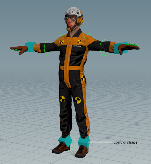
Posing a character with a control shape 
-
Create a
 Rig Pose SOP node and then connect the output of the Attach Joint Geometry SOP node node to the input of the Rig Pose SOP node.
 -
In the Rig Pose SOP node’s parameters lock any transform parameters that you don’t want the control to access. For example, for a
head_controlyou may want the control to only access the Rotate parameter, and not the Translate or Scale parameters. -
Turn on the Selectable Template flag for your network’s Joint Deform SOP node and then select the Rig Pose SOP node and turn on its Display flag.
Example: Joint Deform and Rig Pose Nodes and Erik with his control shapes. Character model courtesy of Christophe Desse. -
Click in the viewport and press Enter to enter the Rig Pose SOP's viewport state.
Example: Erik with his control shapes in the Rig Pose viewport state. Character model courtesy of Christophe Desse. -
Select the control shape.
The manipulator handles appear around the joint the control shape is assigned to.
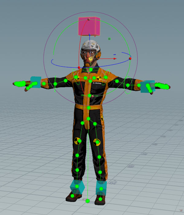
Example: Selected control. Character model courtesy of Christophe Desse. A new Transformations multiparm for the control appears in the Rig Pose node’s parameters.
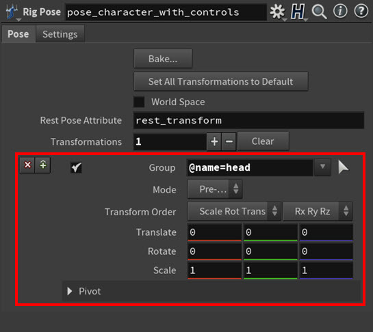
Example: Rig Pose node’s parameters with new multiparm -
Use the control shape to transform the joint as you desire.
Any transform changes you make to the control shape’s target joint are inherited by the control shape’s geometry. This way you will always know the transform state of a joint just by looking at its control.
Example: Adjusting the rotation of the head with the control. Character model courtesy of Christophe Desse.
| See also |