VELLUM CLOTH: TIPS & TRICKS
VELLUM CLOTH: TIPS &TRICKS
The improved character tools for Vellum in Houdini 18 introduce some superb new features and workflow techniques designed to better improve accuracy and realism, and, overall, assist in making the development of a cloth simulation a relatively straight-forward and art-directable process.
In this tutorial, I will guide you through some good workflow practices when working with Vellum Cloth in Houdini 18. I will begin by talking about the initial set-up and discuss which geometry types are favoured in terms of a cloth simulation, followed by best practices for preparing incoming intersecting collision geometry, and, finally, end with a troubleshooting example and some useful tips and tricks for post-sim fixes.
Let’s get started!
Using a Planar Patch
The input geometry for a cloth simulation is important because this will affect how the material will behave, and so it is useful to understand which types of geometry work best. Using a planar polygonal patch, for instance, is often superior to a using a regular grid. This is because a planar polygonal patch is geometry constructed with a randomized collection of uniformly sized triangles, and so its structure achieves smoother, more organic results.
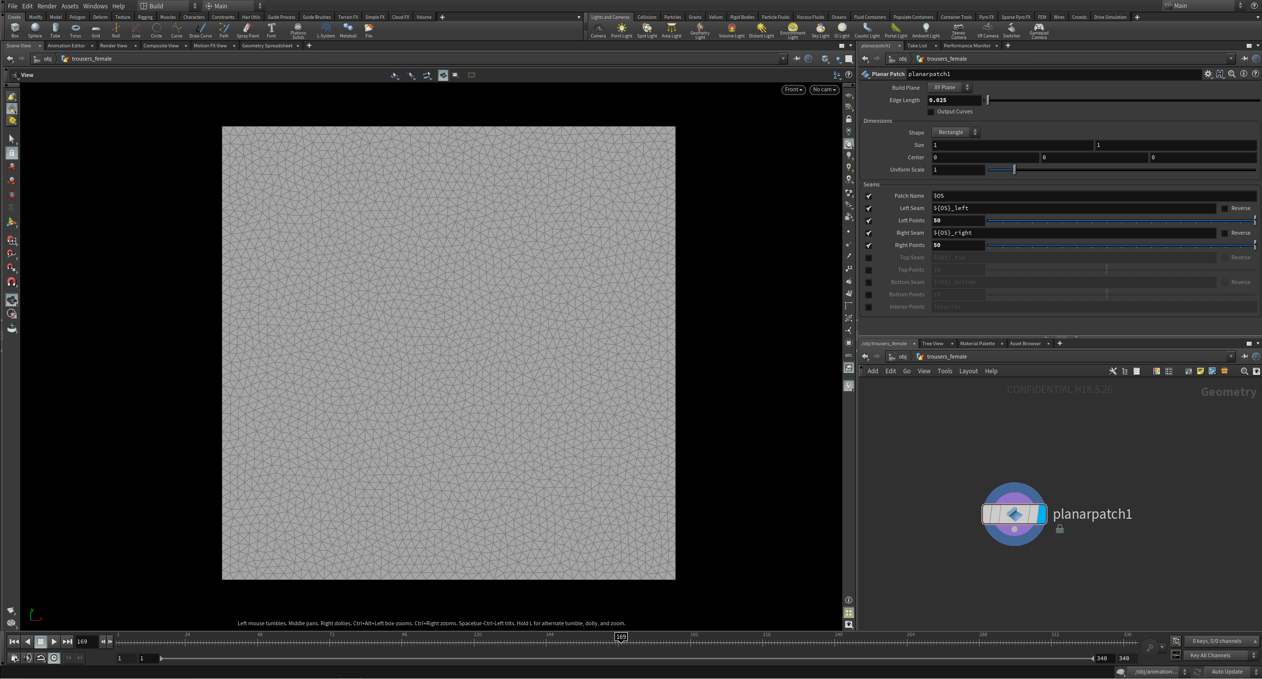
The planar patch is advantageous when compared to a regular grid because it achieves smoother looking results at a lower resolution; which, in turn, is beneficial for optimizing your scene. A regular grid will often require a greater resolution to attain similar looking smooth results.
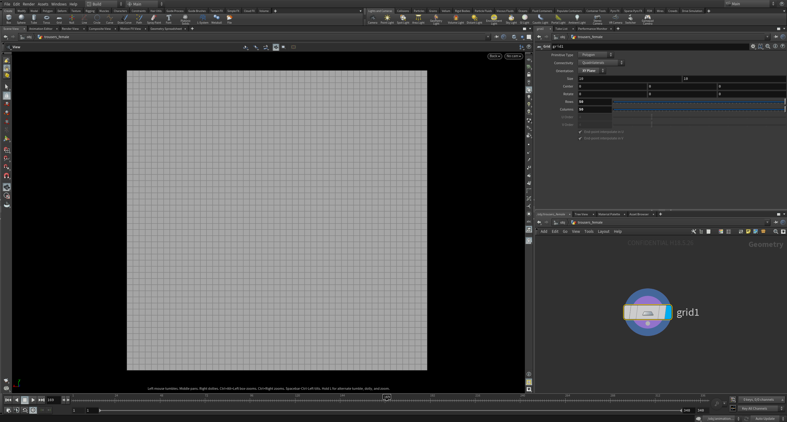
You can use a Remesh SOP after a regular grid to achieve a similar construction to a planar patch, however, the planar patch is favored, particularly when making clothing, because it also allows exact specification of boundary point counts to make procedural stitching possible. This is particularly useful where different panels need to be stitched together.
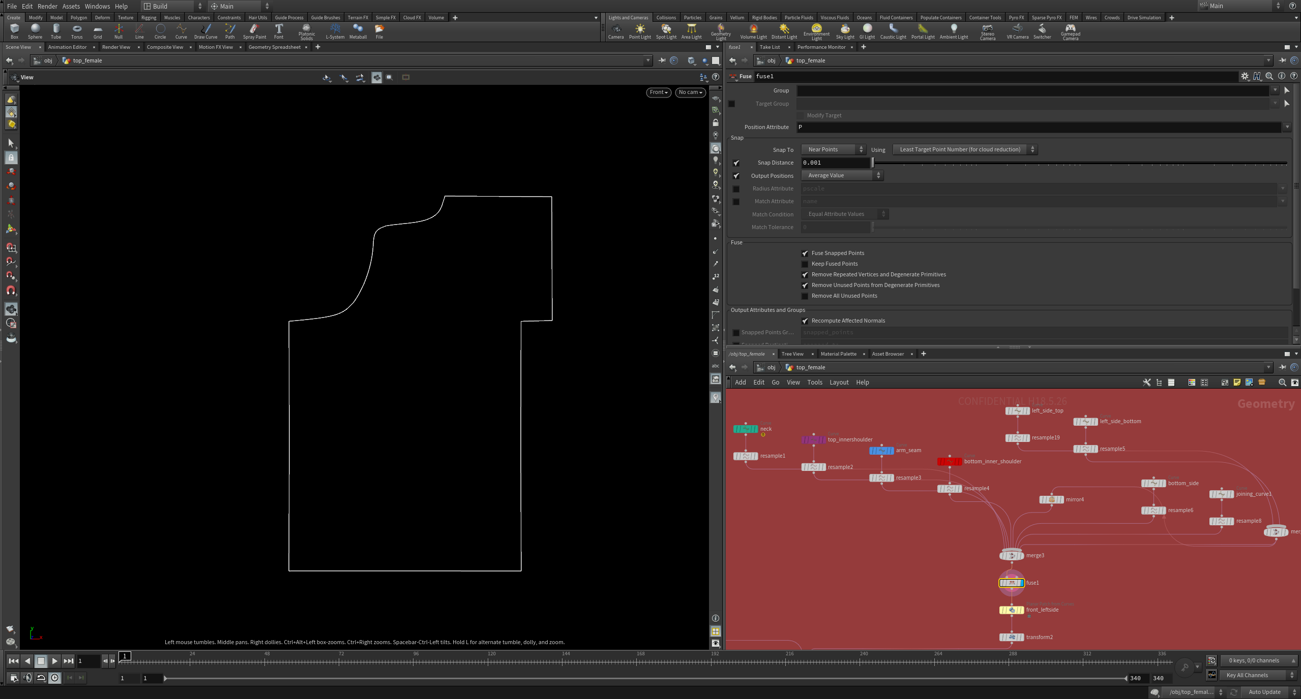
For custom clothing panel shapes that are not square, however, I tend to draw curves and use the ‘Planar Patch from Curves’ node. A Resample SOP after each drawn curve allows for the same procedural control for boundary point counts.
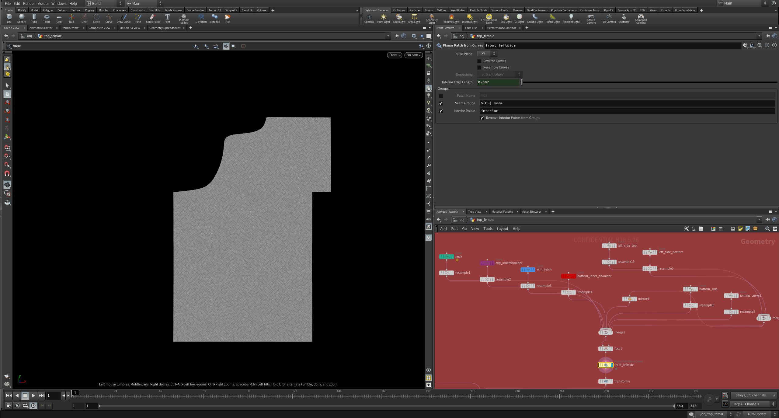
The suitable edge length required for your cloth will depend on your Bend Stiffness values, and the type of material you would like to make. For instance, stiffer cloth will require higher Bend Stiffness values, and so a lower resolution may be used. In comparison, a softer material like silk will require lower Bend Stiffness values, and a higher resolution will be needed. You can test and optimise this according to your scene.
Fixing Intersecting Collision Geometry
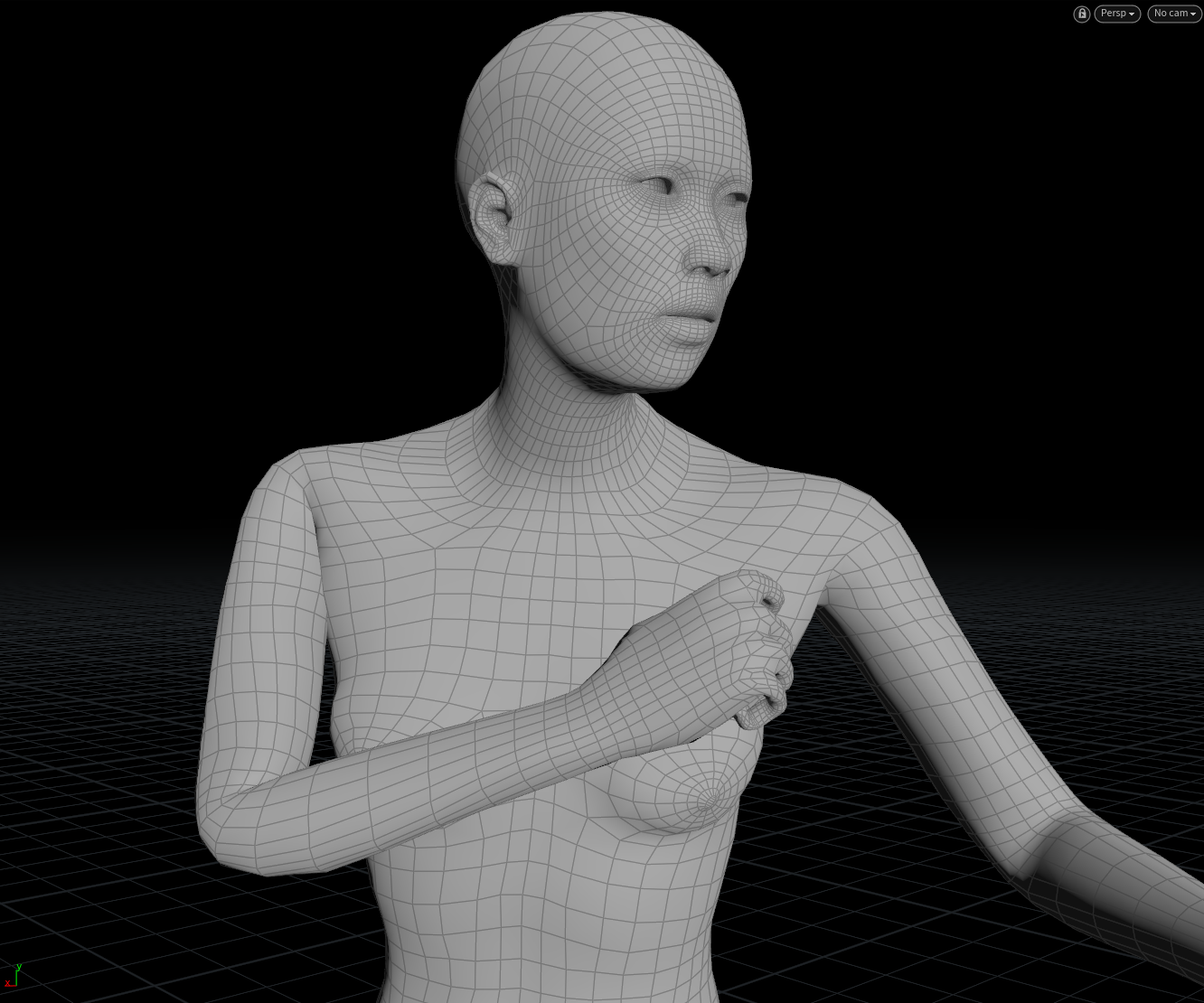
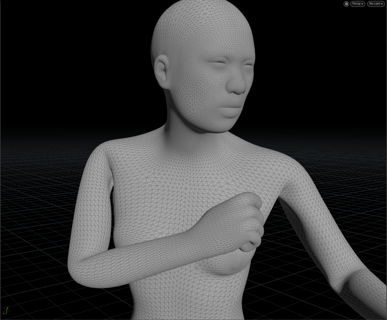
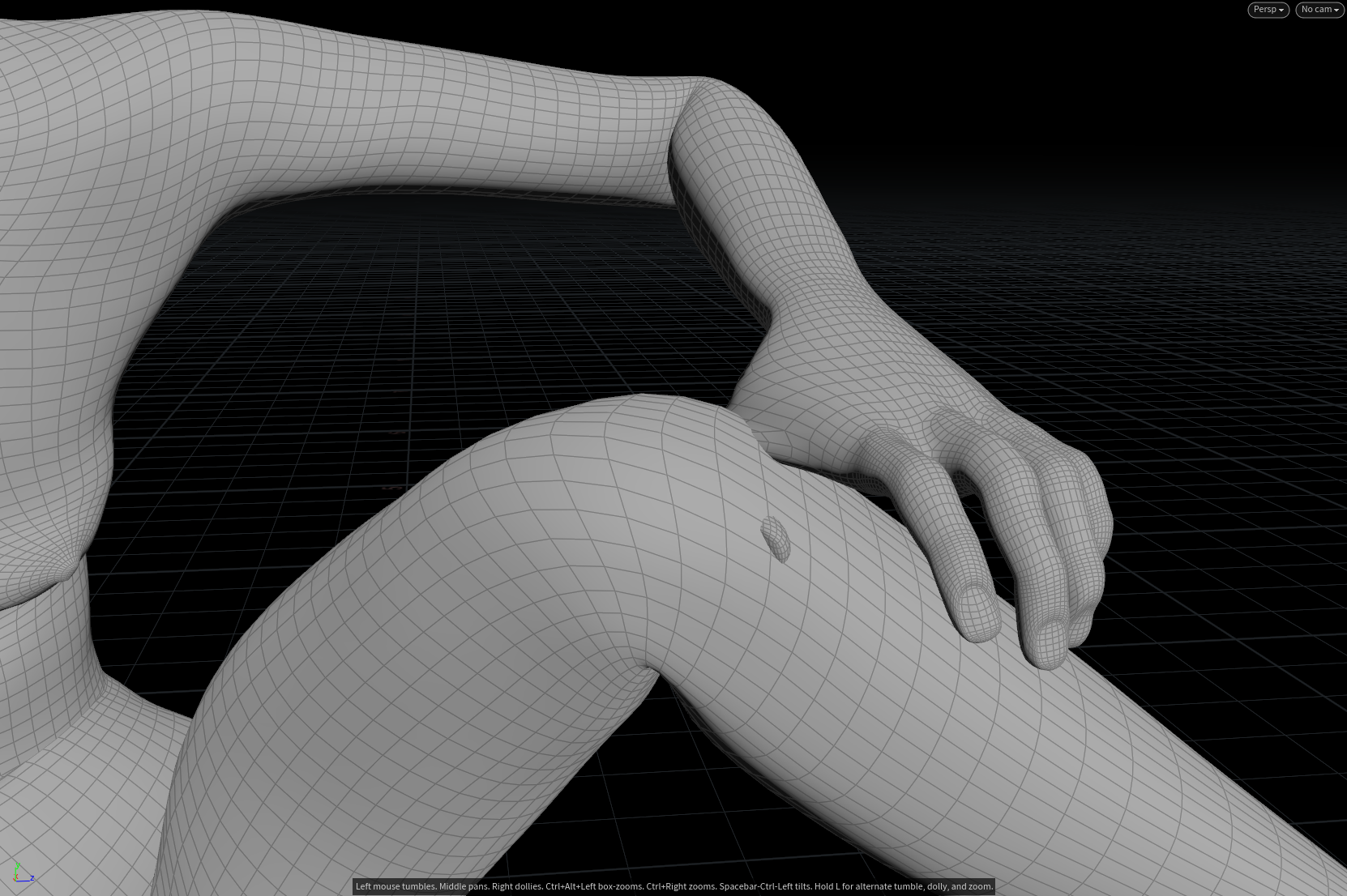
In some cases, you may be working with animated collision geometry that intersects with itself. This can be problematic and later can cause errors for the cloth solver, because the cloth geometry will have no room to go. In this example, the upper arm intersects with the chest. We will take a look at a helpful technique for remedying this issue, by turning the entire collision geometry into a Vellum Cloth object and using soft and hard Pin Constraints. Before we begin, I tend to use a Peak SOP to slightly increase the thickness for the collision geometry - I find this a useful precautionary measure as it allows a bit of breathing space for the cloth, and will hopefully avoid any post-sim intersecting problem areas.
Steps
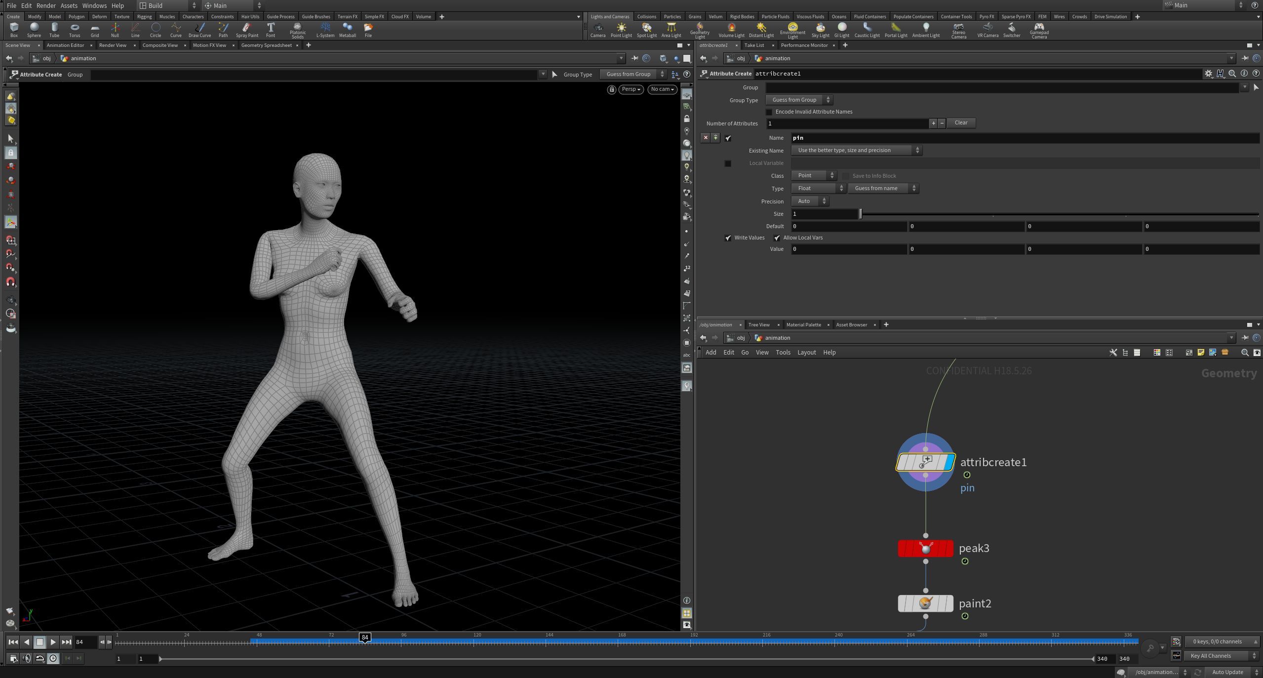
1. Firstly, create an attribute called ‘pin’ using the Attribute Create SOP.
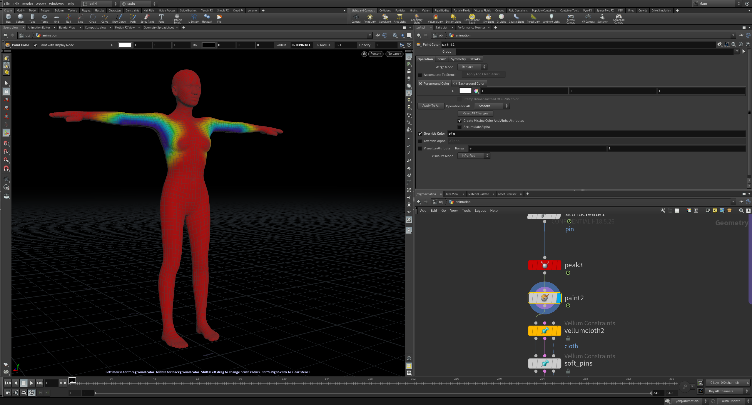
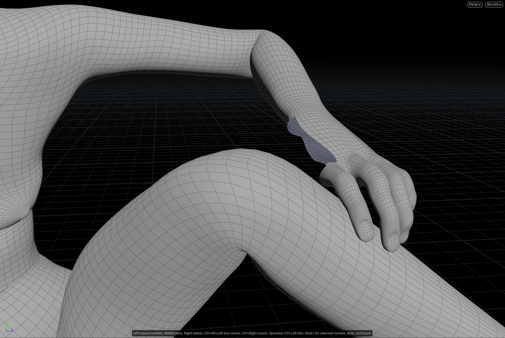
2. Use a Paint SOP with an override for the newly created pin attribute. Red areas have a value of 1 and will retain its original shape, while blue areas have a value of 0 and will become soft and malleable.
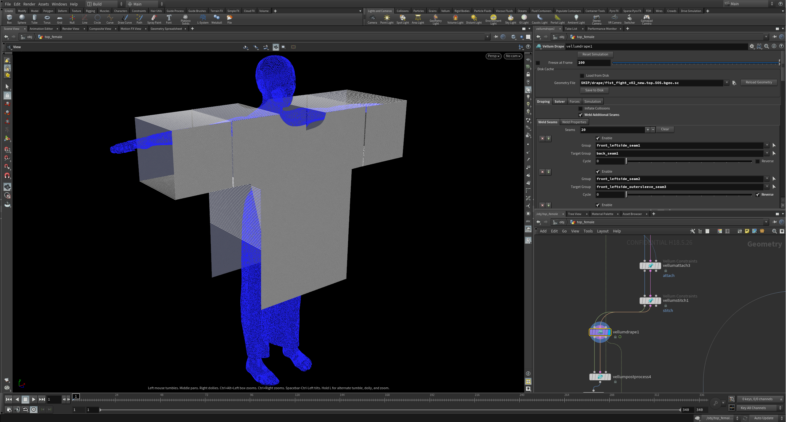
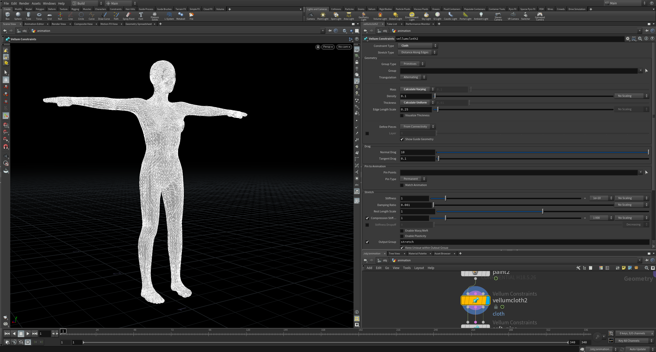
3. Use ‘Vellum Configure Cloth’ to give the entire collision geometry Vellum Cloth Constraints.
4. Create a ‘Pin to Target’ constraint set to ‘Soft’ and check ‘Match Animation’. Set the group to ‘@pin<1’; this will ignore all red areas that have a value of 1. This will now act as the soft constraints for the parts of the collision mesh you want to deform.
5. Set the stretch stiffness to a lower value to allow some varying stiffness over these points.
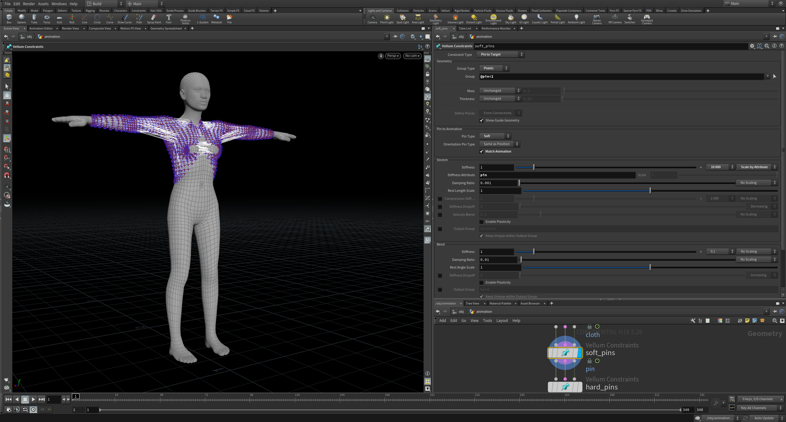
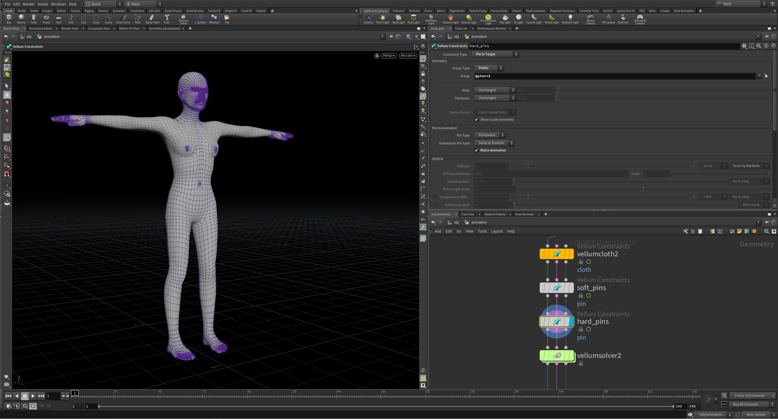
6. Create a second ‘Pin to Target’ constraint set to ‘Permanent’ and check ‘Match Animation’. Set the group to ‘@pin == 1’; this will ignore all the non-red areas that have a value less than 1. This will now act as the hard constraints for the areas of the collision mesh you don’t want to deform.
7. Set the Stretch Stiffness to 1e+10 for an infinitely stiff strength.
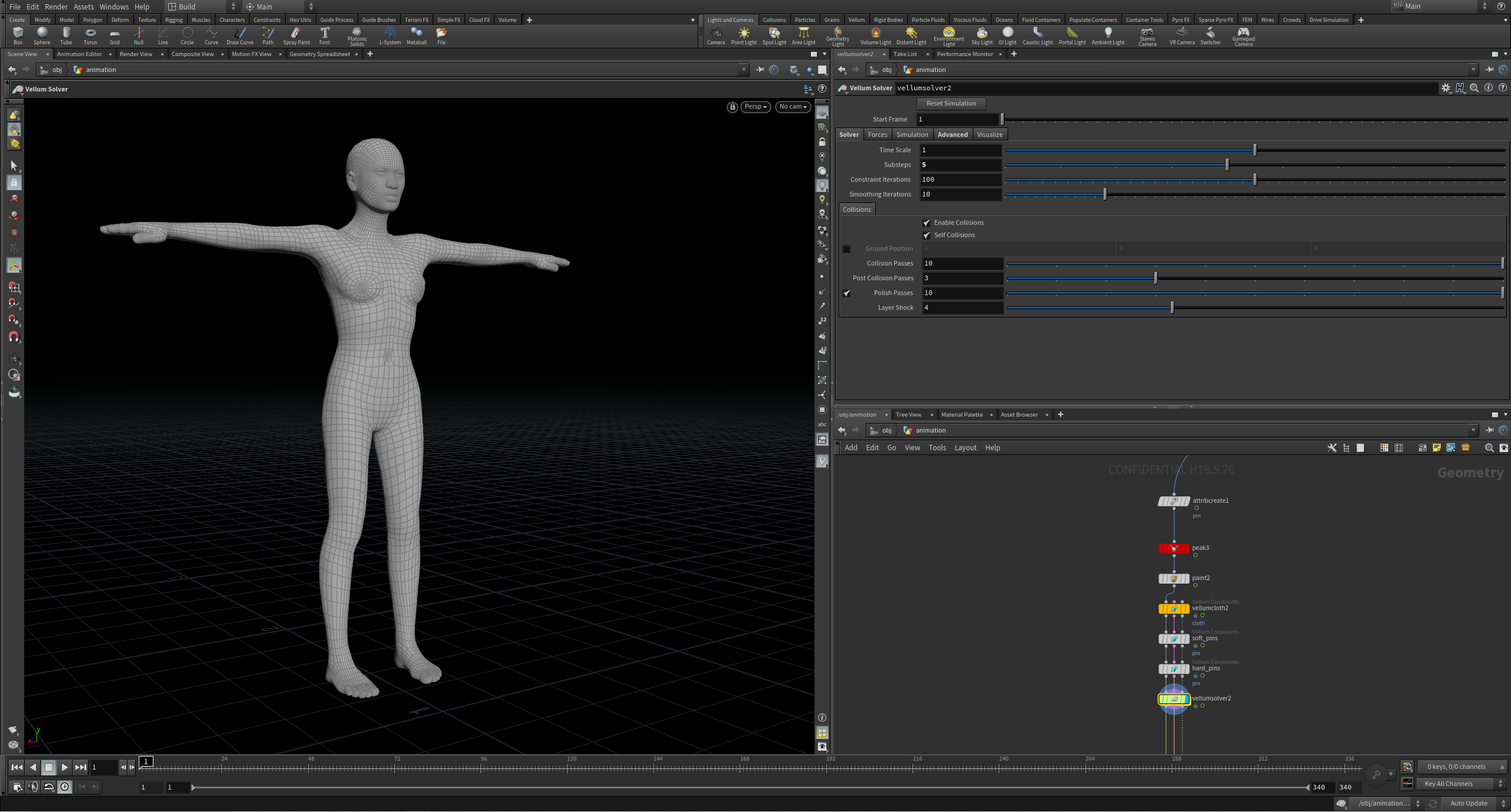
8. Finally, set the Substeps value to 5 for more accurate collision results.
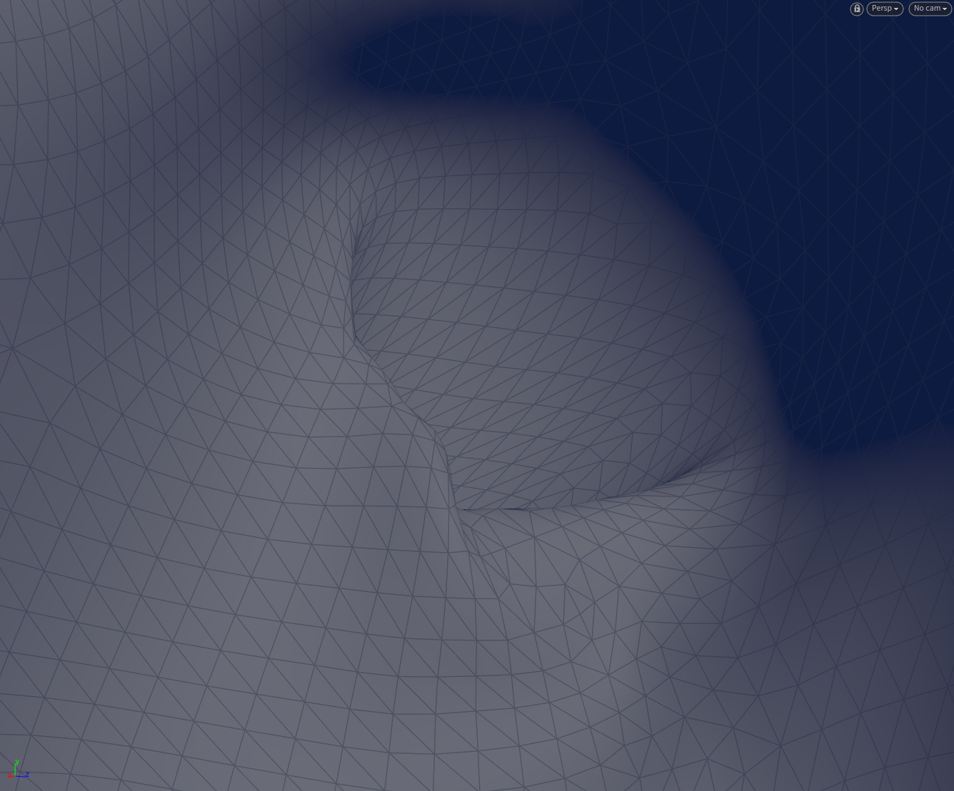
Once solved, the result will be an unchanged animation for areas on the collision geometry with a red painted value of 1, and all non-red painted areas with values less than 1 will be soft and shape-able, thus allowing intersecting collision areas to be deformed and resolved. This will create a gap between intersecting collision geometry, allowing both sets of constraints to be satisfied as the cloth will have space to move.
In some cases, it may be wise to blast areas with extreme intersections, especially if they are not needed for the sim. In this example, the thumb can simply be removed.
Troubleshooting and Workflows
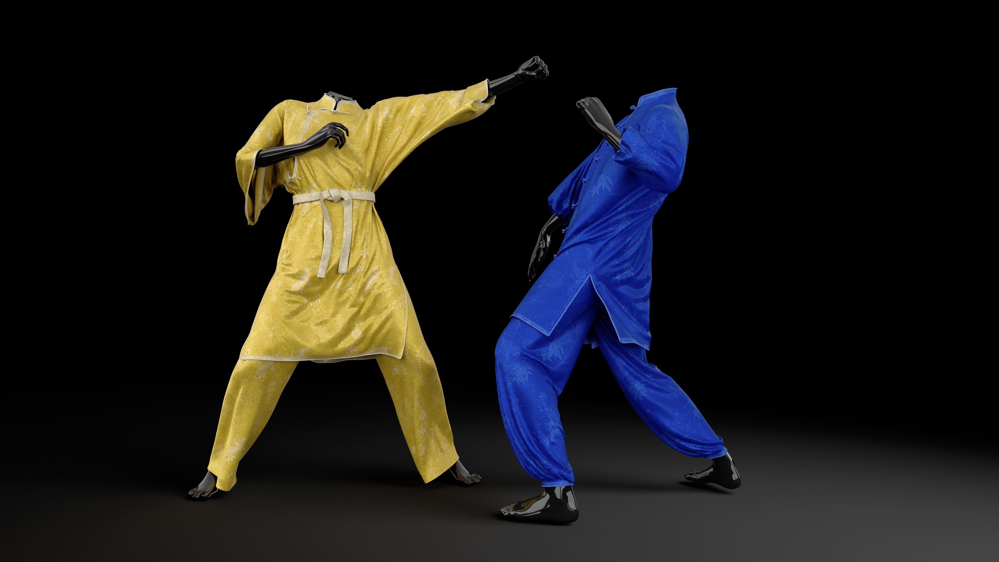
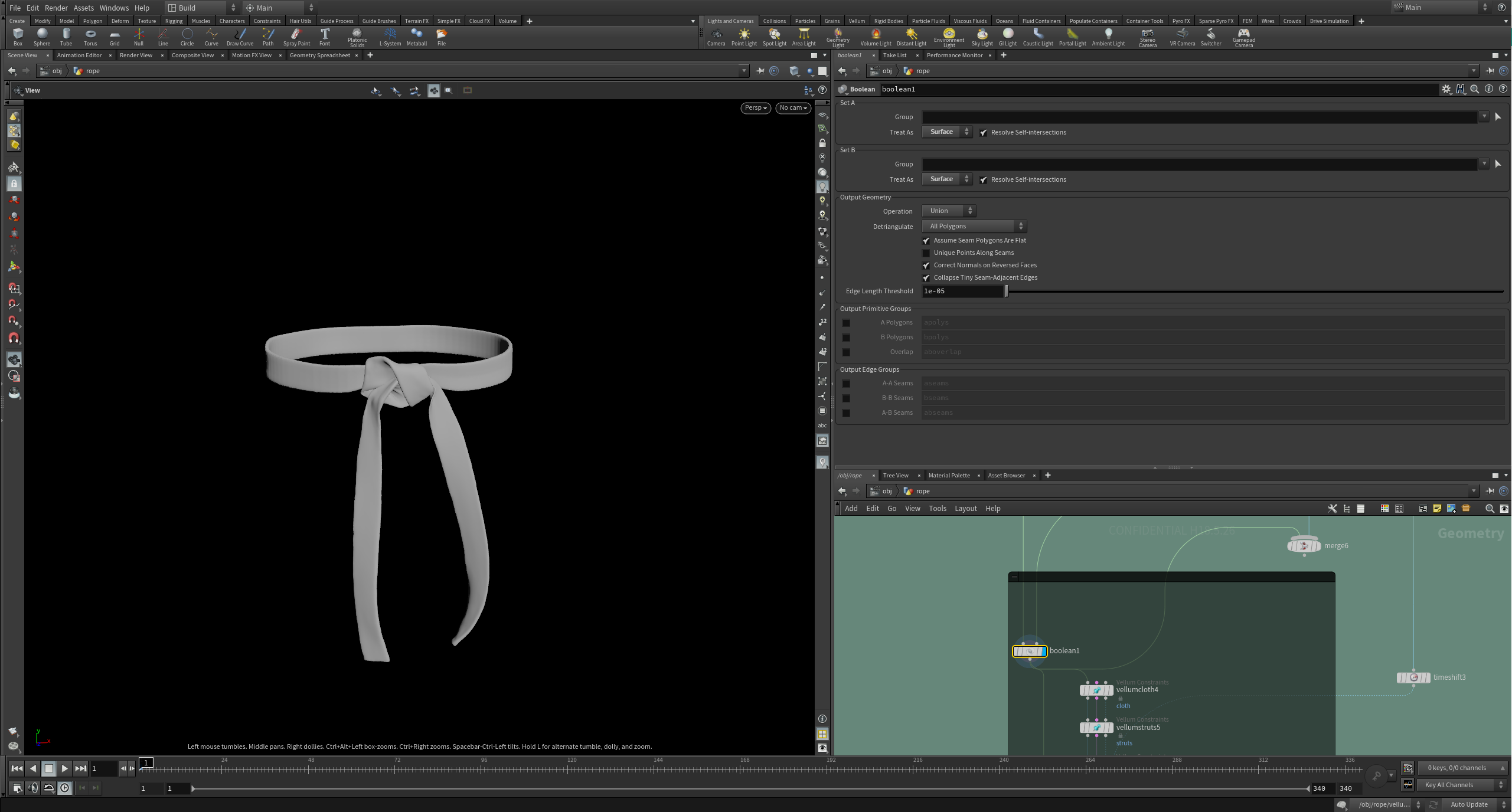
The belt geometry for the martial arts shot took quite a bit of troubleshooting and development, and so in this section I will talk a bit about how I created and simulated the belt to achieve the final look.
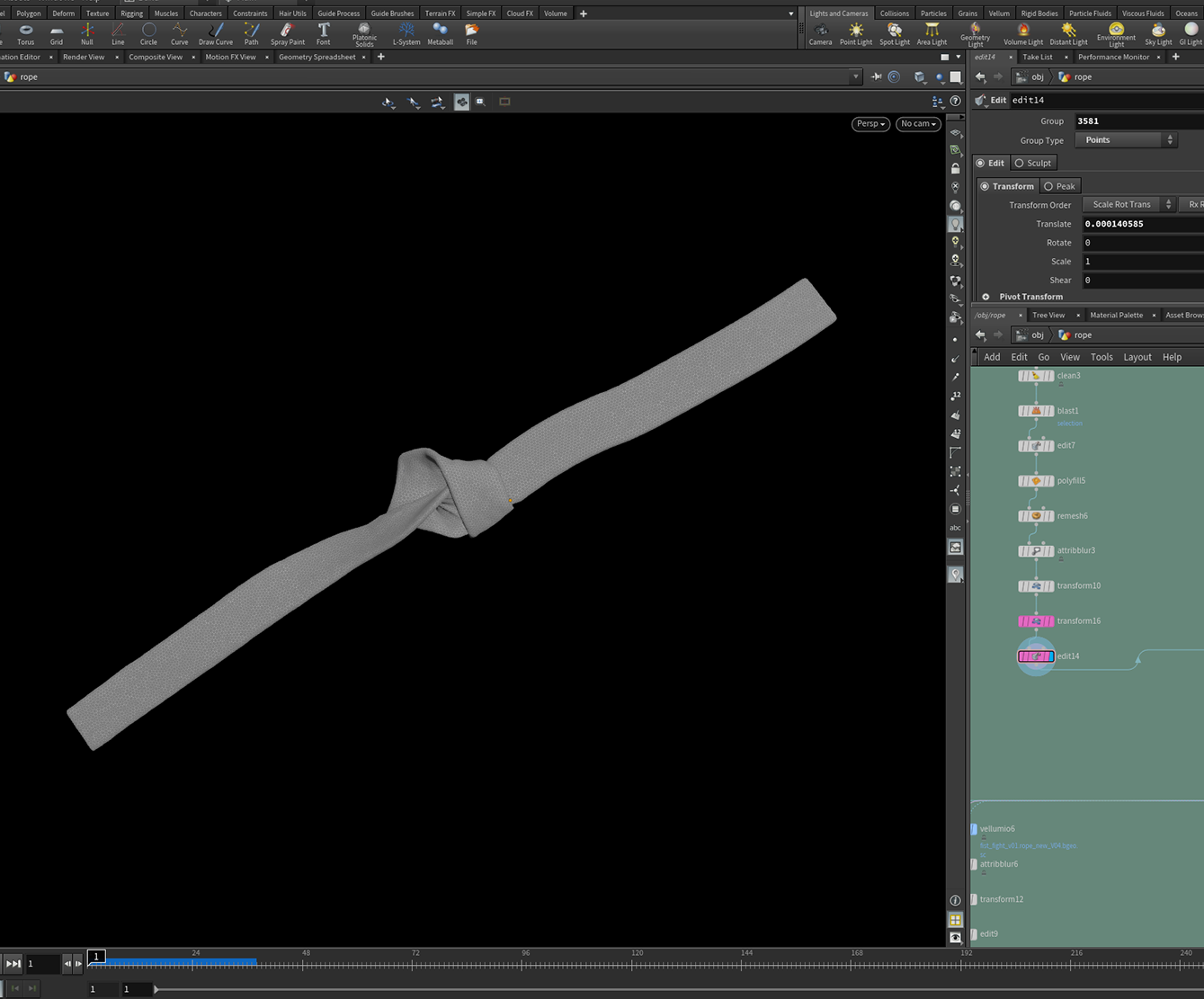
After some tests, I decided to simulate the knot in the belt using Vellum to determine the initial knot geometry. This gave me greater control and better accuracy compared with solely modelling the knot.
I modeled the waistband of the belt separately and used a Boolean SOP to combine the two geometries.
Once I had this initial geometry, I clipped the tails and used the main waistband with the knot as a collision object for the top. Here, I used an animated transform to pull the top in at the waist, and so achieving accurate deformations and creases for the initial top state.
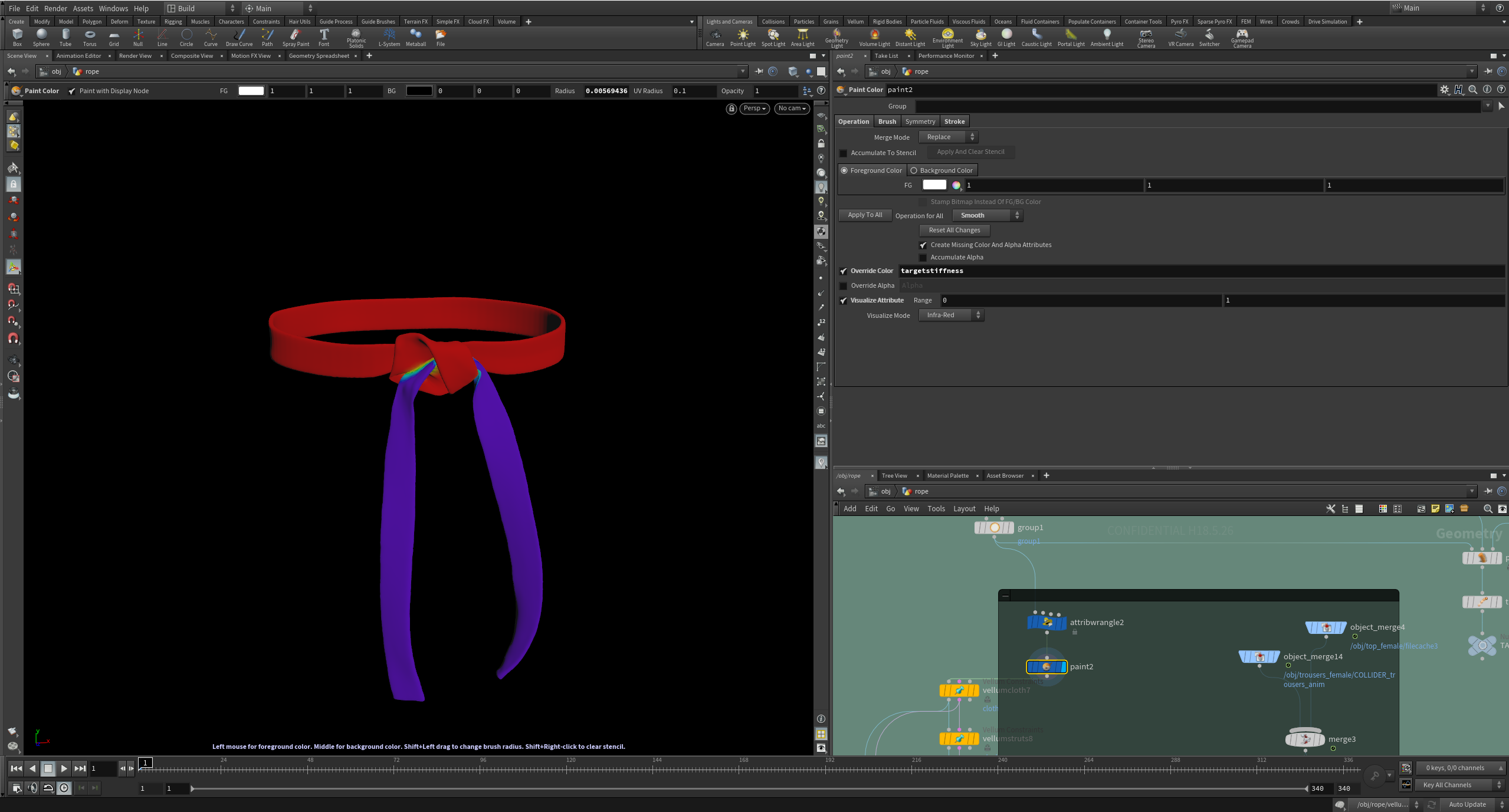
Once the initial top state was set, I painted custom attributes whose values acted as a driver for determining which areas would move freely and which areas would keep shape.
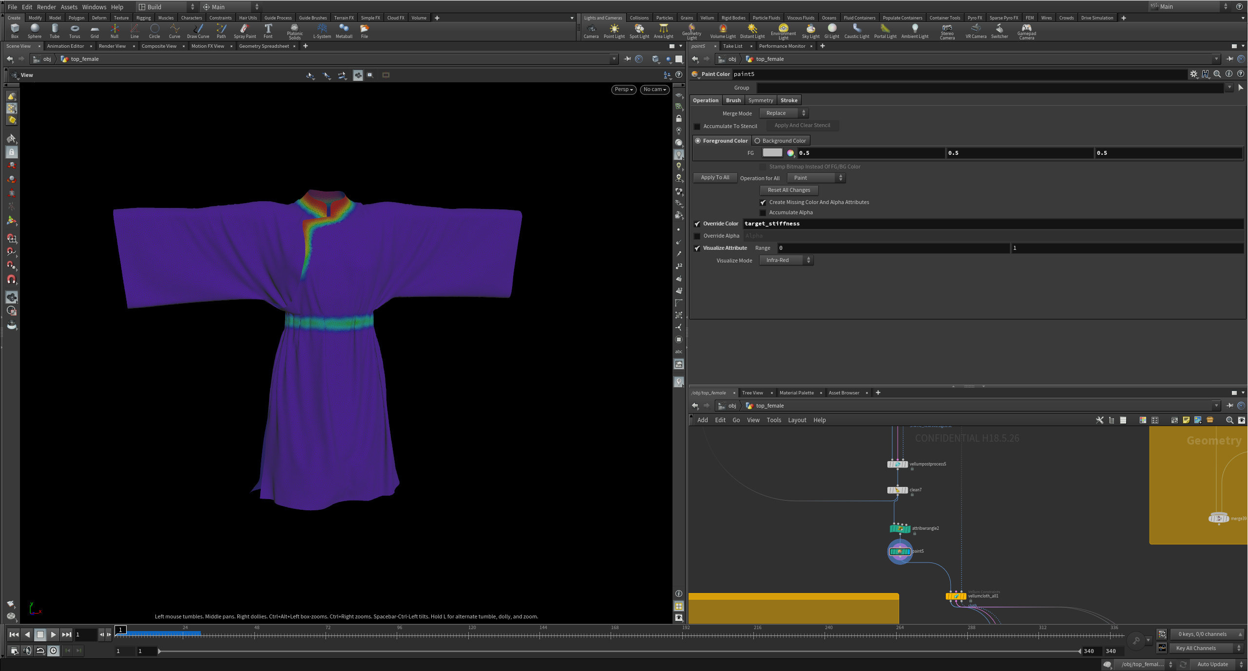
Since the top was simulated separately and prior to the belt, the newly simulated top cache would now act as the collision geometry for the belt. The custom paint attributes method could again be applied and determine which areas of the belt would keep shape and which areas would be free to deform.
- Create a point group on the section of geometry you want to focus on; here, I have made a point group selection on part of the belt. This group can be called 'for_rivet'
- Append a Null after the group called 'OUT_rivet'
- At obj level, create a Rivet Node and specify the path for the Rivet Geometry; this will be the newly created Null 'OUT_rivet'
- Specify the Point Group 'for_rivet'
- Check 'Keep Position When Parenting' in the Transform section of the Camera
- Parent the Camera to the Rivet
POST-SIM CLEAN UP
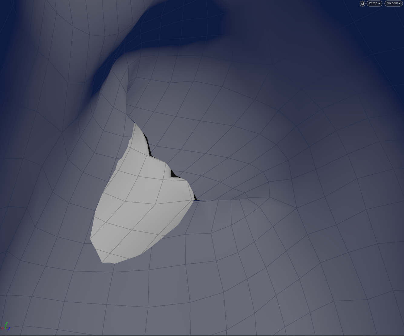
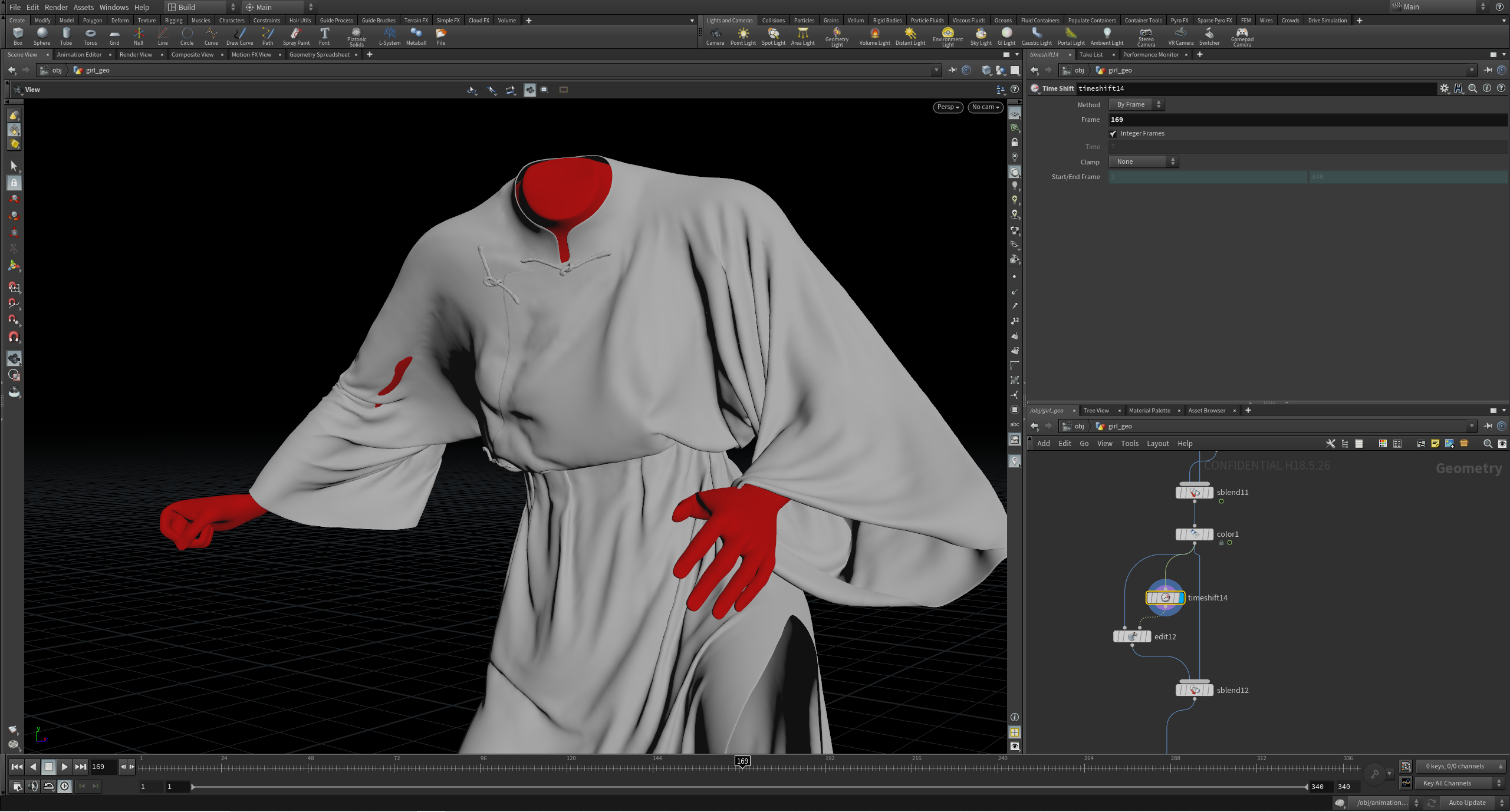
Though we had cleaned the collision geometry prior to the sim, and gave it extra thickness using the Peak SOP, there may still be cases where the collision geometry penetrates the cloth geometry cache when merged together post-sim.
In cases like this, where penetration is visible, but not detrimental, we can use the second input of the Edit SOP to make a deforming edit on the animated collision geometry. This can later be blended using an Sequence Blend SOP with the original cloth mesh for a seamless post-sim fix.
Steps
Scrub through your timeline to locate the frames with the problem areas
Use a Time Shift SOP to freeze the mesh on that frame
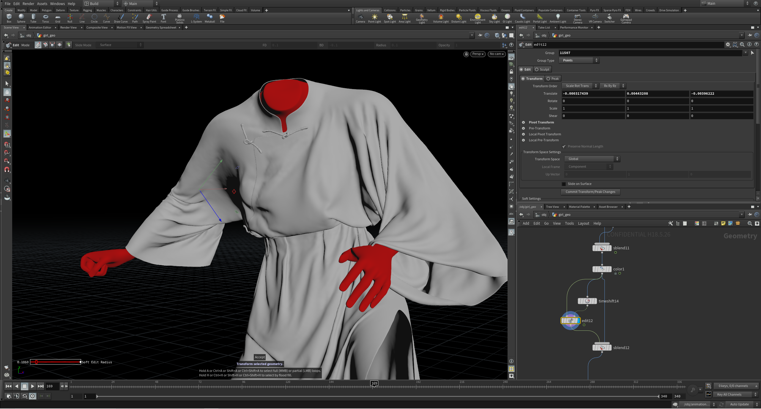
Append an Edit SOP; the first input will be your Geometry to Edit (the animated cache), and the second input will be the Reference Geometry (the static mesh from the Time Shift)
Make your edit to fix the intersection - usually, I tend to make edits on points with a Soft Radius so to achieve a smooth result
Now, when scrubbing through the timeline, the edit will also transform with the moving geometry
Key frame a Sequence Blend SOP between the original cache and the newly created Edit SOP for a seamless transition between geometries

Isabel Kokuti
About the Author
Former SideFX Intern and Masters graduate from Bournemouth University, Isabel is a Houdini Technical Artist currently working in Feature Films. She is from England and she specializes in Character FX.
CREATED BY

COMMENTS
MoltenCrazy 6 years, 5 months ago |
Hi, Isabel! Thanks for the tutorial.
Is the animated FBX file available? The included file is the static T-pose.
MoltenCrazy 6 years, 5 months ago |
Whoops...never mind. Missed the note in the file. :)
nox_zahra 6 years ago |
Hello!
I'm having trouble figuring out how you attached the belt to the garment. Did you attach it to the animation, or is it a vellum cloth? Thanks for any help that you can give.
Zigmund 4 years, 8 months ago |
Hi,
I have a couple of questions. I have noticed that the last vellum solver refers to the Target1, but I didn't find any in the file. So should we use a target for the final simulation or is it just left from some intermediate setup?
I have also noticed that after the drape node you use post process node but after the vellum solver there is i/o vellum node. Could you please provide some clarification why do you use post process node in one case and i/o vellum node in the other?
Thanks!
JamesMaxwell 4 years, 5 months ago |
Hi, Thanks for the tutorial. It is very useful. I want to be able to simulate the wrinkles and crease that appear in the costumes of Pixar animated characters, but unfortunately those creases are not created in my character's cloth in Houdini, the priests which described by Andriy Bilichenko's HIVE seminar for different cloth material does not work for me. I give it a try, but other than jean's pants (denim) other priests did not work properly. What solutions do you suggest for me? I use Houdini 18.5.
Thank you very much.
mutsumi_abe 2 years, 3 months ago |
Hi, Thank you for the tutorial. I'm a beginner so it really helps.
When I open a HIP file that was downloaded here, warnings messages were loaded : Load warnings for Side_FX_tutorials/Vellum_Cloth_Tips_Tricks/Vellum_Cloth_Tips_Tricks.hip
Warning:
/obj/top_female/front_leftside:
Skipping unrecognized parameter "removeinteriorgroups".
/obj/top_female/front_leftside_outersleeve:
Skipping unrecognized parameter "removeinteriorgroups".
/obj/top_female/front_rightside:
Skipping unrecognized parameter "removeinteriorgroups".
/obj/top_female/back:
Skipping unrecognized parameter "removeinteriorgroups".
/obj/top_female/back_leftside_outersleeve:
Skipping unrecognized parameter "removeinteriorgroups".
Could you please show me how to deal with the parameter "removeinteriorgroups"? I use Housini 20.0. Your feedback would be greatly appreciated.
Please log in to leave a comment.