| On this page |
Erosion is one of the most important nodes when it comes to terrain creation. In nature, terrains, and landscapes are shaped by erosion. Erosion is caused by water, ice, wind, glaciers, but also heat and cold. Erosion shapes landscapes over time by removing material from the Earth’s surface. The material breaks, crumbles, and is ground into increasingly finer material. This process results in fine sediments such as sand, silt, or clay. Erosion brings different terrains together and it’s the connecting element that combines patches, terraces and other features to create a believable and naturally-looking terrain.
In Houdini, you differentiate between two fundamental types: Water-based erosion and thermal erosion. The first type is typically labelled as “hydro” from the Greek word “hydros” for water. Thermal erosion is caused by differences in temperature and the term originates from the Greek word “thermos” for warm.
To simulate this process, you typically use the ![]() Heightfield Erode SOP. There are many examples and use cases throughout this guide that illustrate what the HeightField Erode SOP can do.
Heightfield Erode SOP. There are many examples and use cases throughout this guide that illustrate what the HeightField Erode SOP can do.
Basic usage 
Again, you can start with the basic heightfield setup consisting of a ![]() HeightField SOP and a
HeightField SOP and a ![]() HeightField Noise. To simulate erosion, lay down a HeightField Erode SOP, and connect its first input with the output of the noise node. When you turn on the erode node’s blue Display/Render flag, you’ll see two main features: erosion channels and smooth
HeightField Noise. To simulate erosion, lay down a HeightField Erode SOP, and connect its first input with the output of the noise node. When you turn on the erode node’s blue Display/Render flag, you’ll see two main features: erosion channels and smooth sediment areas. In fact there are also debris, flow and flowdir layers. The channels are not a separate layer, but the result of the erosion process.
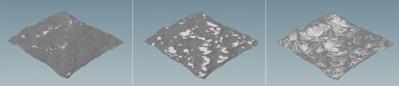
With a ![]() Heightfield Visualize SOP, you can make the various layers visible. There, you have nine slots for various layers. Below you can see the
Heightfield Visualize SOP, you can make the various layers visible. There, you have nine slots for various layers. Below you can see the debris, sediment and flow layers.
Erosion is a time-depending process and this means that you can change the look of the terrain with a simulation. The erode node’s Freeze at Frame defines for how many frames the simulation should run. If you don’t like the result, you can start again with Reset Simulation. You can also turn off Freeze at Frame if you want to watch/render the erosion process or create an animated flipbook.
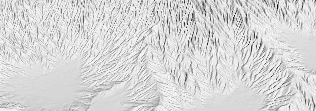
The Erosion Feature Size determines the scale of the “channels”. Smaller values create more detail and finer structures, but the quality of the erosion features also depends on the heightfield’s resolution. Below a value of 3 or 2 you normally won’t see any changes. The new erosion algorithm creates the typical look of the channels with a branched and “feathered” structure. The image below shows the complex pattern you can achieve with the new erosion model.
Spread Iterations controls the amount of sediment. With higher settings, the smooth areas become bigger, because more and more material will fill the deeper areas.
The parameters of the Hydro section simulate the flow of water and the amount of material that is being removed from the terrain. The Hydro parameters have stronger impact on the terrain’s shape as the Thermal parameters. You can play with the various settings and there’s no global rule for wrong or right values.
Tip
Terrains often look better with a slight amount of distortion - even when they're eroded. As always, this depends on your scene and if you want to preserve the structures, you can terminate your network with erosion.
With default settings, the HeightField Erode SOP tends to remove large amounts of material. To restrict the amount of rock being entrained, you can decrease Flow Force. If you want to simulate different types of rock with different hardness, you can use a mask. The entire range of erosion parameters accepts masks. Another parameter that strongly affects the terrain’s look is Spread Iterations. With high values, the eroded material is transported for longer distances and tends to fill valleys and level the terrain.
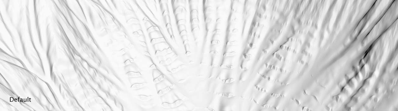
With smaller values for Flow Force and Spread Iterations you’ll be able to maintain more terrain structures like terraces. The left image of the comparison below shows terraces with the erode node’s default settings. The right image uses a Flow Force value of 0.3 and Spread Iterations is set to 25.
Erosion stacking 
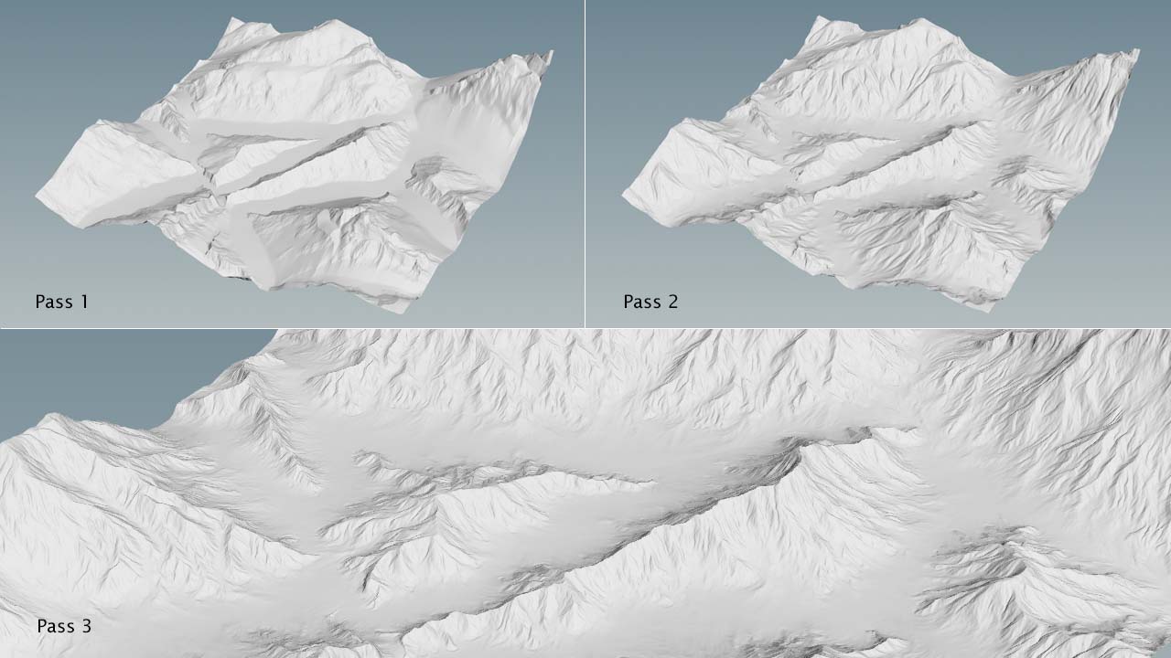
A typical workflow with erosion is stacking. This means that you don’t apply just one HeightField Erode SOP, but you do multiple iterations with different nodes. You apply masks to identify certain areas, you change parameters like Erosion Feature Size or Flow Force, and you distort the results. This way it’s possible to create very realistic terrains with lots of features.
The workflow is straightforward. When you start with the first erosion node, you typically create the larger features, for example with an Erosion Feature Size of 20 or more. If you want to erode more material, you can also increase the node’s Freeze at Frame parameter. The default value is 5. Once you've found working settings, you don’t have to store the current state. Instead, you connect the output of the first erosion node to another downstream erosion operator. The new node will take the current state, for example from frame 10, and uses it as the basis for the next erosion pass. This way you can create erosion cascades and each pass adds more detail to the underlying structures.
You can also add ![]() HeightField Distort by Noise SOPs between the erosion nodes to get more variance and a rougher look:
HeightField Distort by Noise SOPs between the erosion nodes to get more variance and a rougher look:
HeightField → HeightField Noise → Erode → Distort > Erode → Distort → Erode → Distort…
The advantage with this setup is that it’s fully procedural. You can change any parameter at any point in the network without having to update the entire node chain. You also normally don’t have to resample the terrain between the individual erosion passes.