| On this page |
Patterns are a convenient way to create exotic landscapes, but also realistic terrains like dunes. Furthermore, you can patch patterns to other heightfields, or use a certain structure as a starting point for something more complex.
You can apply patterns through the ![]() Heightfield Pattern SOP and choose from six different modes. The following examples show you how to use patterns to create certain terrain structures.
Heightfield Pattern SOP and choose from six different modes. The following examples show you how to use patterns to create certain terrain structures.
Note
All examples start with a ![]() HeightField SOP on Houdini’s obj level. Create the node and double-click it to dive inside. This will be the basis for your networks.
HeightField SOP on Houdini’s obj level. Create the node and double-click it to dive inside. This will be the basis for your networks.
Example: Desert field 
The HeightField Pattern SOP provides modes that are suited for the creation of a typical desert field with eroded hills, ripples and rocks that stand out from the sand. This example combines two patterns to get structures of different size.
Hills 
The first “layer” creates the large hill structures and a mask will break the pattern. The mask cares for a more natural look, because wind is often shielded by obstacles like rocks and this results in height differences.
-
Set the HeightField SOP’s Grid Spacing to
1for a higher resolution. -
Add a HeightField Pattern SOP and connect its first input with the output of the HeightField SOP.
-
Open the Pattern section’s Pattern dropdown menu. From there, choose Ramp to generate a saw tooth pattern.
-
Decrease Height to
30. This will flatten the pattern. -
On the Position section, change Size to
190. Instead of nine steps you’ll now see just five edges. -
On the Ramp Remapping ramp, click the
 Presets button. From there, choose Hill.
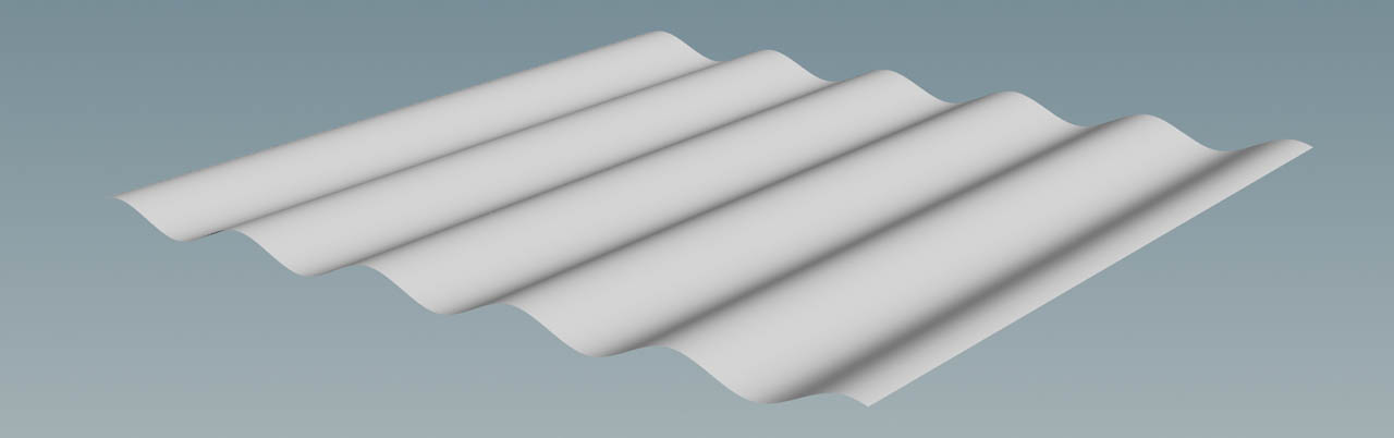
The pattern is now a smooth and wavy surface.
Shaping the hills 
The hills should be formed by wind, similar to dunes. Dunes also have a specific profile: there’s a steep slope on the windward side. On the wind shadow side, however, you can see how the sand is blown away and forms a stretched trail. You can recreate this characteristic shape when you modify the Ramp Remapping curve.
Click the little triangle below the ![]() icon to expand the parameter section. Now you can enter an exact Position for each control point to shape the curve.
icon to expand the parameter section. Now you can enter an exact Position for each control point to shape the curve.
-
Click the left slider. For Position, enter
0.15. This will shift the slider to right. -
For the slider in the middle enter Position value of
0.3. -
Finally, click the right slider. Here, Position will be
0.7. Now, the waves follow the new profile. Your curve should look as in the image below.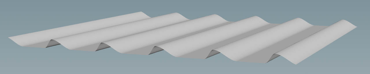
-
On the Distortion section, turn on Distort Pattern. You’ll immediately see a change, but the pattern is still too regular.
-
To create strongly curved structures, set Amplitude to
850. This value results in a noisy surface, because the noise pattern is quite small. -
To get rid of the spikes, increase Element Size to
700. The hills look better now, but they're still too irregular. -
Decrease Roughness to
0.2to smooth the edges and create a regular structure.
Masking 
-
Lay down a
 HeightField Mask Noise SOP and connect its first input with the output of the heightfield. Link the output with the second input of the pattern node. The node will now sit between the heightfield and the pattern nodes. The mask flattens the hills and creates irregularities.
 -
To create more noise, decrease Element Size to
140. -
For more contrast, open the Post Processing section and set Gain to
0.98.
Ripples 
The ripples overlap the hills and you can reuse the noise mask to create height differences. The ripples also add extra detail to the hills and later you’ll see how the ripples create nice structures in conjunction with erosion.
-
Add another HeightField Pattern SOP and connect its first input with the output of the already existing pattern node. Link the second input with the output of the mask node.
-
From the Combine with dropdown menu, choose Add to merge the ripples.
-
Set Pattern to Stripes.
-
The ripples should only support the dunes and some more structure. Therefore, decrease Height to
7. You can now see parallel bands that cover the hills. -
On the Position section, change Size to
20and create more ripples. -
Go to the Distortion section and turn on Distort Pattern.
-
Set Amplitude to
25to get higher “waves”. -
With an Element Size of
125you can remove the high-frequency noise.
Blurring 
The terrain in its current state pretty jagged and ripples also show rather hard edges. Some moderate blur will help to remove artifacts, but keep the overall impression.
-
Put down a
 HeightField Blur SOP and connect its first input with the output of the last pattern node.
 -
Change Radius to
3.5.
Noise 
Right now the terrain’s base is entirely flat, but it'd be nice to have some more structure. The ![]() HeightField Noise SOP adds an irregular rock surface with highly customizable peaks and hills. This fundamental node is part of almost any heightfield network.
HeightField Noise SOP adds an irregular rock surface with highly customizable peaks and hills. This fundamental node is part of almost any heightfield network.
-
Add a HeightField Noise SOP and connect its first input with the output of the blur node.
-
The terrain shouldn’t be too high, so set Amplitude to
200. -
For Element Size, enter
300to get more noise.

Erosion and distortion 
The ![]() HeightField Erode SOP brings everything together and creates a realistic terrain. The default settings, however, create rather disappointing results.
HeightField Erode SOP brings everything together and creates a realistic terrain. The default settings, however, create rather disappointing results.
-
Lay down an erosion and connect its first input with the output of the noise node.
-
To get stronger erosion, increase Freeze at Frame to
60. -
The erosion channels are very wide and there’s hardly any detail. For smaller structures, set Erosion Feature Size to
3. -
With Spread Iterations you can control the material transport. With
80, for example, you’ll get bigger sediment areas that fill the space between the hills. -
On the Hydro tab, decrease Flow Force to
0.5to get less erosion from water.
A ![]() Heightfield Distort by Noise SOP breaks the erosion pattern and gives everything a more rocky appearance.
Heightfield Distort by Noise SOP breaks the erosion pattern and gives everything a more rocky appearance.
Example: Trench 
You can use the HeightField Pattern SOP to create a trench with debris and sediment, flowing down its slopes.
-
Add a HeightField Pattern SOP and connect its first input with the output of a HeightField SOP.
-
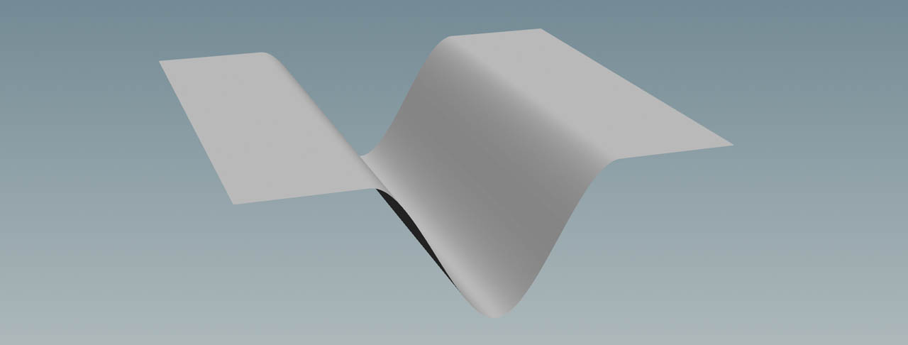
Go to the Pattern section’s Pattern dropdown and choose Ramp.
-
On the Position section, go to Size and enter
500. You’ll now see a surface with a single “saw tooth”. Then, turn off Repeat. -
On the Ramp Remapping ramp, click the
Presets button. From there, choose Valley. -
To move the deepest point of the trench to the grid’s midpoint, go to the Position section and set Phase to
0.5. -
Change Height to
300and get a really deep canyon.
You might have noticed that the new height shifted the grid along the positive Y axis. If you want to level the surface again, set Base Height to -300.
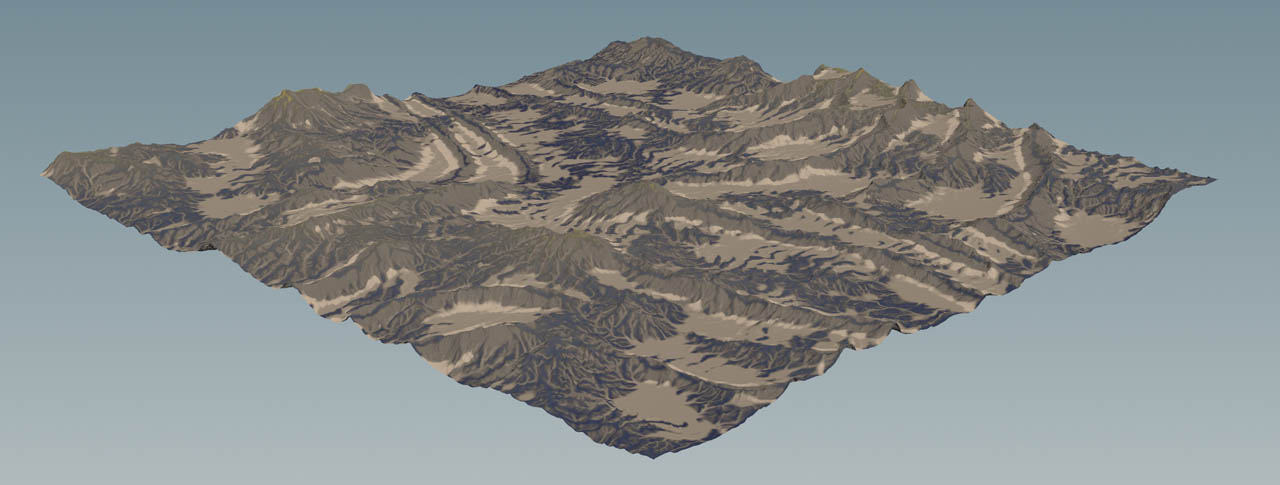
Shaping the terrain 
Lay down a HeightField Noise SOP and connect its first input with the output of the pattern node. You can proceed with the default values or apply a different look. This is totally up to you.
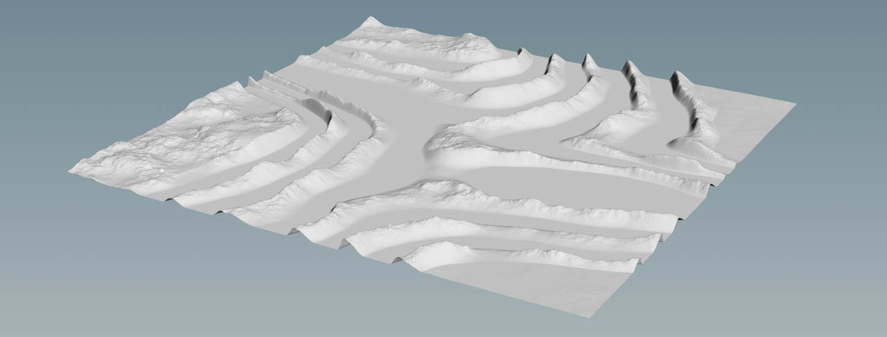
The next steps create the usual noise to get peaks and the rough structures of a rocky terrain. The terrain from the image uses four alternating nodes: erosion → distortion → erosion → distortion. The first erosion node adds large structures with an Erosion Feature Size of 30. Distortion breaks the pattern, while the second erosion node adds the detailed trenches with a feature size of 10. Another distortion node is responsible for the small structures on the smooth erosion area.
The result is a canyon with nicely shaped and feature-rich cliffs.

Example: Adding slope 
The HeightField Pattern SOP is perfectly suited to create inclined terrains. From the node’s Pattern, choose Steps. Then, set Step Height to 0.
With Rise over Run you can control the slop’s inclination, while Rotate lets you tilt the terrain. A value of 1 creates a grid with an inclination of 45 degrees.