| On this page |
Houdini’s heightfields provide a wide range of nodes that help you to refine, change, convert, and manipulate terrains. This chapter is a loose collection of nodes that don’t require a complete page.
Note
The basic setup for the examples on this page always consists of a ![]() HeightField SOP and a
HeightField SOP and a ![]() HeightField Noise SOP. You can proceed with the nodes' default settings.
HeightField Noise SOP. You can proceed with the nodes' default settings.
Here, the HeightField SOP’s Grid Space was decreased to 1 to reveal more structures, but you can also leave the standard value of 2 to speed up the creation process.
Shelf tools 
Houdini’s shelf is a convenient way to access preconfigured tools that serve as examples or starting points for your own experiments. For heightfields there are also several shelves available, but you have to turn on some of them manually.
The Terrain FX shelf is visible by default. This shelf contains several examples to get you started. You can, for example, create a solitary mountain, a moonscape with craters, sand dunes and many more.
To show the invisible shelf tools, go to the shelf. There you can see several tabs like Lights and Cameras, Collision, etc. - and a ![]() button.
button.
-
Click the button to open a dropdown menu and choose Shelves.
-
Turn on the shelves you want to hook to the UI, e.g. Terrain Tools.
The terrain shelf collections contain the entire range of heightfield nodes from the tab menu for fast access.
|
|
|
|
|
|
|
|
|
HeightField conversion 
Heightfields are 2-dimensional volumetric grids, not actual geometry. This circumstance makes it sometimes difficult or even impossible to perform certain operations. The flip side of the coin is that real geometry, made of points and polygons, requires much more resources.
One of the biggest advantages with geometry is that you can create and add all kinds of attributes. Attributes are Houdini’s DNA, and you can use them to control any aspect of a model, a texture or a render. You also have a third dimension that lets you manipulate points, polygons, and normals. Masks and layers are also transferred to the polygon representation of your heightfields as point attributes.
A default heightfield with noise allocates 4 MB, while the same terrain weighs in at 183 MB with the standard conversion settings. There are methods to reduce the number of polygons, but in general, the difference is huge.
The centerpiece of the entire conversion process is the ![]() Convert HeightField SOP.
Convert HeightField SOP.
Conversion settings 
The Convert HeightField SOP provides a Convert to dropdown menu with three options.
With Density you control the quality of the converted object. Higher values create more polygons/voxel, but also “heavier” objects. And you have to consider the HeightField SOP’s resolution (Grid Spacing or Grid Samples). You won’t get more detail with an increased Density with a small Grid Spacing value.
Remapping 
The ![]() HeightField Remap SOP lets you change a layer’s values in a separate process. You're not limited to a terrain’s
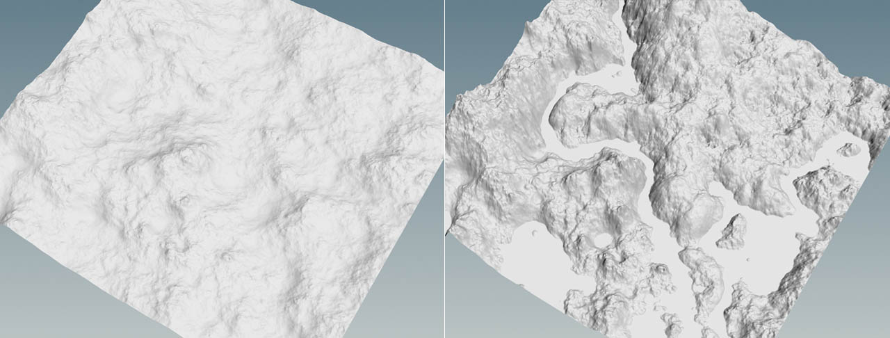
HeightField Remap SOP lets you change a layer’s values in a separate process. You're not limited to a terrain’s height layer, and the method also works with mask values or any other layer. However, the most common application is to remap the height layer. This way it’s possible to create completely different landscapes interactively without having to change the initial values. You can, for example, apply a sea level and turn the terrain into a rocky coast. Or you make a river run through a mountain range as in the example below.
The idea is to define a new minimum and maximum value and then use a ramp to alter all values between these two heights. Imagine you've created a terrain you're happy with, but the terrain’s profile doesn’t meet you expectations. You want more peaks, stepper rock faces and wider valleys. Instead of looking for adequate noise settings, you can use a HeightField Remap SOP and adjust the height values, e.g. with the help of a custom ramp.
Riverbed 
In this example you’ll add a riverbed to a mountainous terrain. The river follows the landscape’s natural conditions and thus has wider and narrower parts.
-
Add a HeightField Remap SOP to the basic setup and connect its first input with the output of the upstream HeightField Noise SOP.
-
Turn the remap node’s blue Display/Render flag.
-
Click the Compute Range button. This determines the terrain’s lowest and the highest points and writes them to Input Min and Input Max
You can also see the input values on Output Min and Output Max. This pair of values keeps the original terrain because input equals output. Change the input values to, lets say, -150 and 100. You will see that lower parts are shifted along the negative Y axis and the terrain becomes deeper. The higher parts are also slightly lowered by approximately 12 meters.
Remapping ramp 
-
The Remap curve provides information about the terrain’s height distribution. The outer left point indicates the lowest value and on the right you have the highest value. When you drag the yellow point on the left upwards, you will notice that the terrains becomes totally flat: now minimum and maximum values are equal.
-
Click on the curve to create another control point.
-
The parameters below now show Point No. set to
3. Change Position to0.4and Values to0.2. -
Create another point. The new point’s Position is
0.5and Value is also0.2.
The Position values can range from 0 to 1 and they're related to the heightfield’s dimensions. In this example, the terrain’s width is 1000 meters. This means that ramp Position values of 0.4 and 0.5 indicate 400 and 500 meters.
For a heightfield that has a width of, let’s say, 1563 meters, the two resulting values are 1563 m * 0.4 = 977.2 m and 1563 m * 0.5 = 781.5 m.
Now you can see a flat area between the mountains. This is the river bed. The area is flat, because here, all height values are equal.
HeightField Crop 
The ![]() HeightField Crop SOP lets you create rectangular cutouts from an existing heightfield. You can also connect any other geometry, but the node will always create a bounding box from this object to define the cropping area.
HeightField Crop SOP lets you create rectangular cutouts from an existing heightfield. You can also connect any other geometry, but the node will always create a bounding box from this object to define the cropping area.
Without a supporting object, you can define Size and Center of the cropping area and its Orientation.
If you want to precisely expand or shrink the cutout, use Voxel Padding. This parameter accepts positive and negative values.
HeightField Cutout by Geometry 
There are situations, where you don’t need an entire terrain, but only a section. The difference to the HeightField Crop SOP is that you can use any geometry to define the area you want to keep or remove. You can rotate, scale, and transform the cutout object in any possible to way to create really fancy shapes. Even animated, deforming, and packed geometry is supported.
The ![]() Heightfield Cutout by Geometry SOP has two inputs. The
Heightfield Cutout by Geometry SOP has two inputs. The
-
first input connects with the heightfield
-
second input expects the geometry you want to use as a cutout.
You can also choose from various Combine modes to create holes or sections, and invert the cutout.
A convenient workflow is to outline the cutout region with a ![]() Curve SOP. Set the curve’s Primitive Type to Polygon and move it below the heightfield, e.g. with a
Curve SOP. Set the curve’s Primitive Type to Polygon and move it below the heightfield, e.g. with a ![]() Transform SOP. Then, connect an
Transform SOP. Then, connect an ![]() Extrude Volume SOP and increase its Depth parameter until the newly created volume encloses the entire terrain. Then you can connect the volume to the HeightField Cutout by Geometry SOP’s second input. This way you get an irregular shape you can refine at any time to optimize your terrain.
Extrude Volume SOP and increase its Depth parameter until the newly created volume encloses the entire terrain. Then you can connect the volume to the HeightField Cutout by Geometry SOP’s second input. This way you get an irregular shape you can refine at any time to optimize your terrain.
HeightField Output 
If you want to export a heightfield’s layers, you can save those as displacement maps through a ![]() HeightField Output SOP. There are couple of things to consider.
HeightField Output SOP. There are couple of things to consider.
Note
This short guide explains only the most fundamental settings. For a detailed breakdown of file formats, export possibilities and color depth options, please read the ![]() node help.
node help.
The first step is to define a Filename.
The Output Type dropdown menu lets you choose whether you want to write a Packed Raster or a Deep Raster.
With the first option, each layer is written into RGBA color channels. Use this option for image formats like PNG or JPG. The number of layers you can export separately is therefore limited to four. The second option writes each layer as a separate deep raster plane. In this case you need a file format that’s capable of creating such a data structure, e.g. PIC or EXR.
To catch all detail from your terrain, Type should be at least 16 b Floating Point, for even better results leave the default 32 b Floating Point option. The latter one corresponds with Houdini’s internal precision for layers. 16 bit and 32 bit also require an appropriate file format like PIC or EXR.
You can also define a custom resolution for your maps. Otherwise the image uses the heightfield’s volume resolution (by default 1000 x 1000). This is important with cropped heightfields or cutouts. In this case it’s better to use a custom resolution, because the maps might become very small as the remaining terrain has only a fracture of the original size.
In the Output Layers section you enter the layers you want to export.
-
Packed Raster. You can add one layer per channel. All available layers are listed in the dropdown menus next to a color channel.
-
Deep Raster. You can specify space-separated lists of layers to save as named image planes. When you enter the layers to (0,1) Layers, all values will be remapped to 0 to 1 range. If you want to use (-1,1) Layers, choose a file format that supports negative values.
You can also subdivide large maps into several separate tiles. Choose, whether you want to tile by size or a fixed number of tiles with Tile Method. Please also consider changing File Naming if you don’t want to use the default UDIM style.
Once you've made your settings, click Save to Disk.