| On this page |
The ![]() HeightField Project SOP lets you add arbitrary geometry to your heightfield. You can define custom mountain shapes, add plateaus in specific locations, or create patterns.
HeightField Project SOP lets you add arbitrary geometry to your heightfield. You can define custom mountain shapes, add plateaus in specific locations, or create patterns.
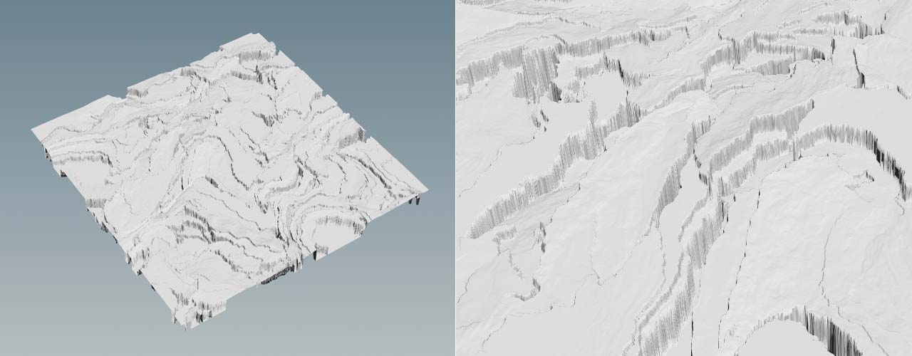
Projection uses rays to catch the original geometry’s shape. This also means that occluded areas that can’t be seen by rays, won’t be projected. You’ll get a solid “wall” in those areas instead. This is due to the fact that heightfields are 2D objects with height information and there’s no displacement in the XZ plane. When you project an object, you just add an offset to the grid’s already existing height information. The quality of the projection also depends on the resolution of the ![]() HeightField SOP’s Grid Spacing parameter. Large spacing creates alias effects and jagged edges.
HeightField SOP’s Grid Spacing parameter. Large spacing creates alias effects and jagged edges.
However, the projected geometry is an integral part of the heightfield and you can apply noise, terraces, distortion, etc. Furthermore it’s not only possible to add geometry, but you can also subtract an object and create impressions like footprints or the caldera of a volcano.
With the project node’s Max Ray Dist parameter it’s also possible to project parts of the object: all parts above the adjusted value will not be considered.
Masking 
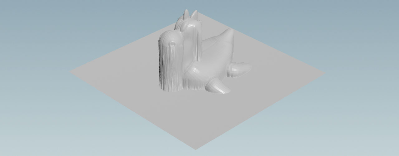
When you take a look at the HeightField Project SOP’s parameter set, you can see a Mask Mode toggle. The image below shows the ![]() Test Geometry: Rubber Toy SOP projected onto an empty heightfield. The project node sends out rays along the Y axis and this creates the typical look with vertical “walls”.
Test Geometry: Rubber Toy SOP projected onto an empty heightfield. The project node sends out rays along the Y axis and this creates the typical look with vertical “walls”.
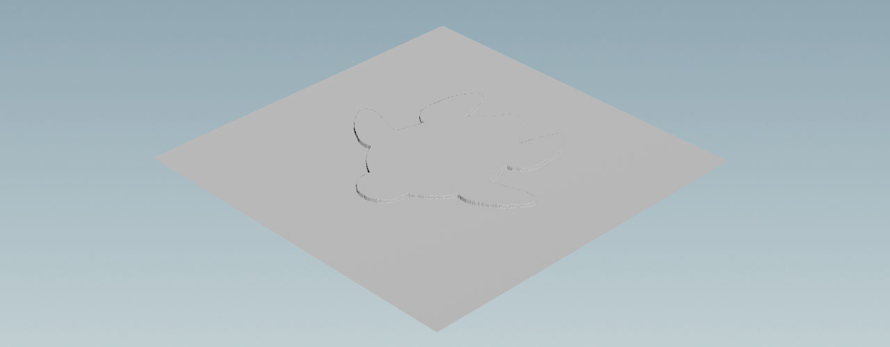
When you turn on Mask Mode, the projection will only happen within a cross-section of the object, because the layer sets the Density value. You can control the final value, by changing Density. With values smaller than 1, the cross section will gradually disappear. It’s also possible to use values greater than 1 to increase the plateau’s height.
Note
The HeightField Projection SOP does not provide an input for external masks. This means that you can’t restrict the projection to certain areas by defining a mask.
Example: Rocky maze 
You can use the combination of scattering and projection to create complex patterns and terrains with just a handful of nodes. When you change the scatter geometry or its distribution, you can also quickly create different versions and looks. Blurring, distortion, and other heightfield modifiers also help to achieve a realistic look. In the following example you’ll use basic cubes to create a maze from mountains and rock.
Tip
On the Solitary mountains page you can also find more sophisticated examples that uses scattering and projection to create a customizable mountain.
Everything starts with a ![]() HeightField SOP to create an empty terrain. The only parameter to change is Grid Spacing. A value of
HeightField SOP to create an empty terrain. The only parameter to change is Grid Spacing. A value of 1 will reveal finer structures.
Scatter object 
The following nodes are the network’s centerpiece. The idea is to scatter instances of a base object over the heightfield grid. Here, the base object is a cube. By randomizing position and scale it’s possible to generate a pattern of partially overlapping cubes and achieve complex structures.
-
Lay down a
 Box SOP from the tab menu.
 -
Change Uniform Scale to
30to get a really big object. -
Then, set Size to
3, 0, 0to stretch the cubes along the X axis. The idea is to avoid very thin and sharp structures by creating a wider base. -
To make the cube sit perfectly on the flat heightfield grid, go to Center.Y and enter
15. This is half the height of the cube.
Scatter points 
The ![]() HeightField Scatter SOP creates scatter points and lets you randomize several parameters like scale and orientation to avoid regulars structures.
HeightField Scatter SOP creates scatter points and lets you randomize several parameters like scale and orientation to avoid regulars structures.
-
Add a HeightField Scatter SOP.
When you turn on the node’s blue Display/Render flag, you can see a very dense point cloud with roughly 227.000 points. At this state you will also create the same amount of instances. Therefore, it’s necessary to decrease point count to a sensible number.
-
From the Scatter Method dropdown menu, choose Total Point Count using Mask Layer. This option lets you determine an exact number of points in the Scattering section.
-
Change Total Point Count to
500. -
Go to the Variability and Relaxation sections. For Range enter
0.5, 2. This will apply a random scale factor between 0.5 and 2.0 to the original box. You can also randomize the boxes' orientation with Randomize Up and Randomize Yaw. -
Connect the scatter node’s first input with the output of the HeightField SOP. Link the third input with the output of the Box SOP.
Now you’ll see 500 overlapping boxes of different size and orientation covering more or less the entire terrain.
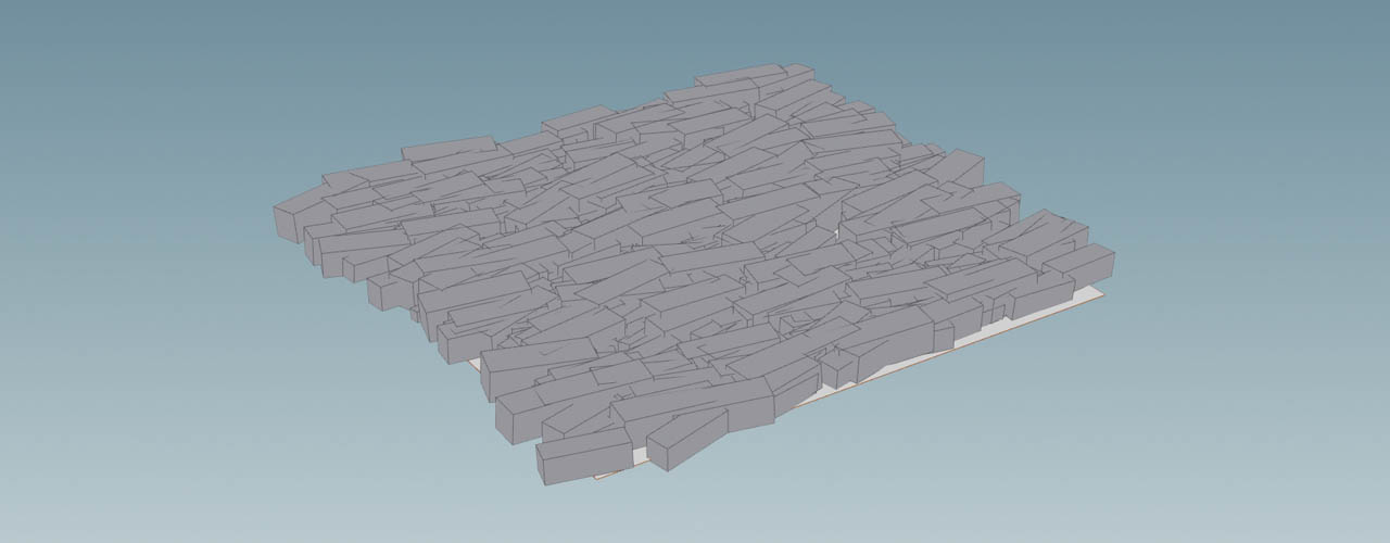
Projection 
This steps modifies the base grid to include the boxes and make them part of the heightfield.
-
Add a HeightField Project SOP.
-
Connect the project node’s first input with the output of the HeightField SOP. Make sure that the heightfield node now has two connections.
-
Connect the second input with the output of the scatter node.
The boxes are now part of the heightfield and you can start to shape the terrain.
Shaping the terrain 
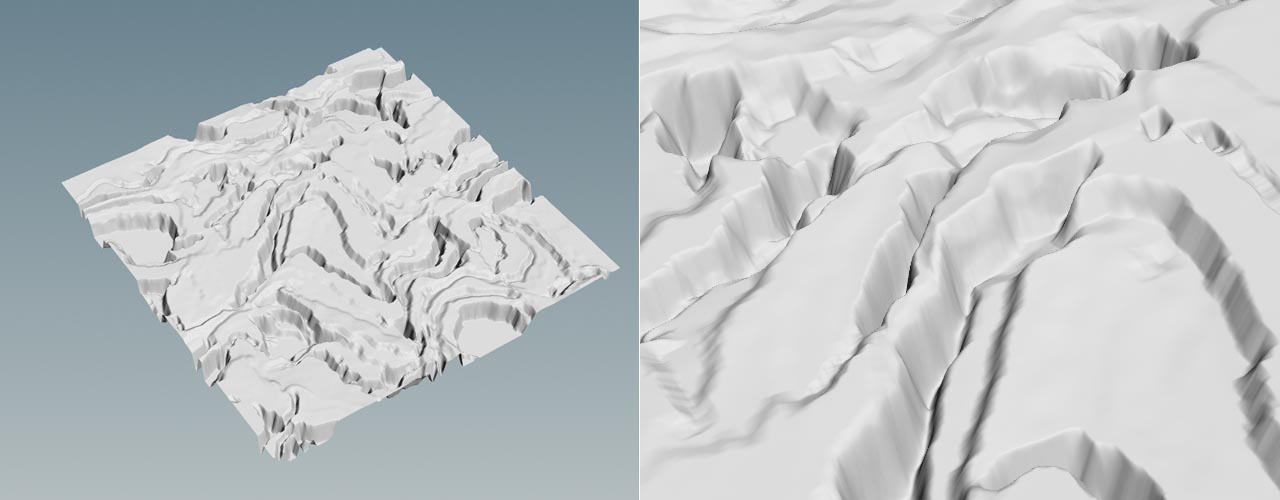
You're free to shape the terrain with any node available and experiment with different settings. A good start, however, is to distort the result of the projection. This will add the actual structure and shape to the terrain, but it can be very noisy. To iron out the spikes, you should blur the heightfield.
-
Start with a
 HeightField Distort by Noise SOP and connect its input with the output of the project node.
 -
From the Noise Type dropdown menu, choose Simplex. This noise type is similar to Perlin noise, but creates smoother results. Curl would add to much distortion.
-
Play with different Amplitude and Element Size values, e.g.
600and375.
Blurring 
Now you can see lots of artifacts at the rocks' “walls”, but you can also get a first impression of how the terrain will look.
-
Put down a
 HeightField Blur SOP to smooth the terrain. Connect its input with the output of the upstream distortion node.
 -
Change the Method dropdown menu to Box Blur. This mode creates softer edges and a more organic look.
-
With Radius you determine the amount of blurring. Higher values will take more voxels into account and you’ll get a smoother impression. Try a value around
6.
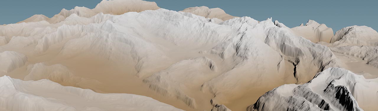
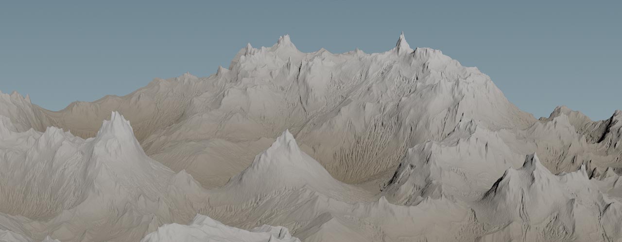
Houdini’s ![]() HeightField Erode SOP and a second HeightField Distort by Noise SOP will help you to finalize the look of the terrain and add more detail.
HeightField Erode SOP and a second HeightField Distort by Noise SOP will help you to finalize the look of the terrain and add more detail.
Mountains 
You can also create mountains with standard SOP geometry like a ![]() Grid SOP and a
Grid SOP and a ![]() Mountain SOP. With geometry you have completely different possibilities to deform an object. Methods that aren’t available with heightfields, because you can work on individual vertices and polygons. The Mountain SOP also supports animation, something that the HeightField Noise SOP doesn’t provide.
Mountain SOP. With geometry you have completely different possibilities to deform an object. Methods that aren’t available with heightfields, because you can work on individual vertices and polygons. The Mountain SOP also supports animation, something that the HeightField Noise SOP doesn’t provide.
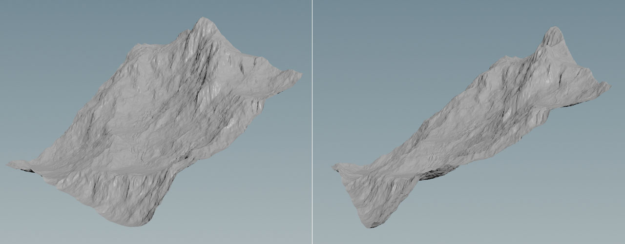
The workflow for projecting mountain geometry is the same as with any other object.
Adding slope 
By default, an empty heightfield is always aligned with two axes, e.g. ZX or YZ. There are Center parameters to shift the terrain’s position within the chosen plane, but you can’t rotate the terrain around X, for example.
To create an inclined heightfield anyway, you can use projection. Note that this approach doesn’t rotate or add inclination to features like noise or other projected objects: mountains will still “grow” vertically along the Y axis.
-
Create a HeightField SOP. You can leave the default settings.
-
Add a
Box SOP. -
Change Size to
1000, 0, 1300. -
For Center, use
0, 290, 0to move the box upwards. -
Now, set Rotate to
30, 0, 0to rotate the box 30 degrees around the X axis. -
Lay down a HeightField Project SOP and connect its first input with the heightfield node’s output. Link the second input with the output of the box.
Now you have a heightfield with an inclination of 30 degrees and you can proceed to add noise, distortion, etc.
Tip
Another method for adding slope is to use a ![]() HeightField Pattern SOP.
HeightField Pattern SOP.