| On this page |
Terraces are topographic features, not layers. They form when a river or sea cuts into an older level, leaving behind flat, step-like ledges. Common types include:
-
River terraces are former valley floors that have been “exposed” by river erosion
-
Marine terraces are former coastlines made visible by tectonic uplift or sea level fall
The typical V-shape of river terraces is the result of erosion processes of varying duration. Near the surface, the rocks were exposed to erosion for a longer time and more of the rock has weathered. The eroded material slides down the valley and is carried away by the river at the bed of the valley.
When you think of terraces, you might imagine huge structures like canyons. However, terraces also occur in relatively small areas like the banks of a creek. To sum up, one can say that terraces are a good method to enhance your terrain’s overall appearance and mimic topographic features.
Out of the box, Houdini’s terraces often look artificial, because they have hard edges. That’s why terraces are typically combined with other nodes and masks to give them a natural look. Even for man-made structures like the famous rice terraces in South Asia, it makes sense to add a slight amount of blurring or some mild erosion.
Houdini’s terraces are always horizontally aligned and there’s no default method for changing their orientation. The height of Houdini’s terraces is also fixed and you need custom solutions to art-direct this feature.
Adding terraces 
The node for creating terraces is the ![]() HeightField Terraces SOP. You can add this node anywhere inside your network, but you need at least a terrain, e.g. a
HeightField Terraces SOP. You can add this node anywhere inside your network, but you need at least a terrain, e.g. a ![]() HeightField Noise SOP. It’s also possible to use multiple terrace nodes with different masks and parameters.
HeightField Noise SOP. It’s also possible to use multiple terrace nodes with different masks and parameters.
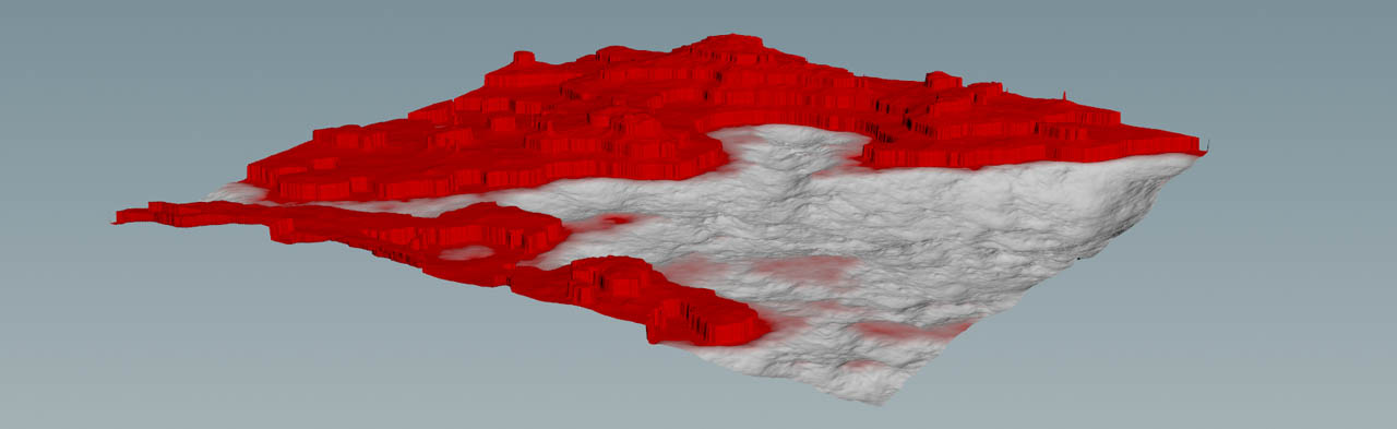
By default, the node creates terraces between a terrain height of 10 and 100 meters. This is the masked area and displayed as a red band on your terrain. To modify this band, change the HeightField Terrace SOP’s Min Height and Max Height parameters. If you're not sure about working values, click Compute Range.
With Fade you can blend terrain and terraces. A value of 0 means that you can see the pure terraces, while 1 will only show the original terrain. When you expand the Terracing section, you will also a see Fade Ramp. This ramp lets you control where you want to see more or less terraces. You should also consider using Smooth Edges for a softer look.
With Max Step Size you control the maximum height of the terraces in meters. As with Fade, you can apply a custom curves to get terraces of different height. However, there’s no parameter that lets you directly create terraces with random height values. This would only be possible through a custom solution.
Mesa and cliffs 
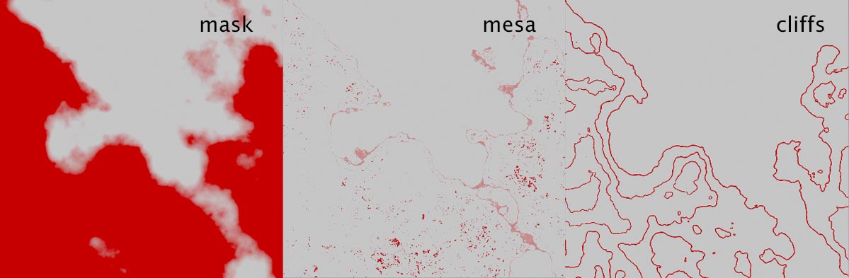
The HeightField Terrace SOP writes out two layers called mesa and cliffs. You can find both layers in the Output Layers section. The first layer (mesa) contains the horizontally clipped areas of the terraces. The second layer (cliffs) represents the vertical parts. Both layers are also masks and you can reuse them, e.g. if you want to scatter rocks and plants only in specific areas.
There are also three slope-based parameters that let you refine mesa and cliffs. However, the impact of the parameters is not always visible. For a better view, you can isolate the layers and adjust the parameters.
-
Add an
 HeightField Isolate Layer SOP and connect its input with the output of the HeightField Terrace SOP.
 -
Turn on the isolate node’s blue Display/Render flag.
-
Go to Layer to Isolate and replace the default entry with
cliffsor, depending on which layer you want to display,mesa. You will now see the 2D projection of the chosen layer. -
Select the upstream terrace node and change the slope parameters. Note that Mesa Max Slope only works on the
mesalayer, while Cliff Min Slope is exclusive tocliffs.
You can also change the terrace node’s other parameters like Min Height or Fade, and observe how your changes affect the layer masks. This often gives you a better impression of what the parameters do.
Example: Inclined terraces 
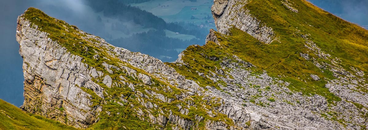
In nature, terraces are often horizontally aligned and the layers are stacked like the pages of a book. However, sometimes you can see inclined or folded layers, esp. in so-called folded mountains like the Alps. There, the African continental plate pushes against the European plate. Tectonic forces push the plates together and fold them. As a result, the rock is squeezed and deformed like layers of caramel.
Just on a side note: Another consequence of this continental motion is that the Mediterranean Sea will disappear some day.
The HeightField Terrace node doesn’t provide any methods to create folded terraces and you need a trick. Basically, the idea is to deform only the terraces through a pattern and reapply them to the terrain.
Distortion pattern 
Note
As in the heightfield guide’s other examples, this setup also starts with the basic network consisting of a ![]() HeightField SOP and a downstream
HeightField SOP and a downstream ![]() HeightField Noise SOP.
HeightField Noise SOP.
You need a pattern to deform the terraces. The base of this pattern is a customizable ramp or curve to create bulges, folds, or a certain degree of inclination. You can also mix multiple patterns to create complex shapes.
-
Add a
 HeightField Pattern SOP. Connect the HeightField Noise SOP’s output with the first input of the pattern node. Now the base heightfield has to connections: noise and pattern.
 -
Turn on the pattern node’s blue Display/Render flag to see the result of your actions.
-
The default pattern is Stars. To change this, go to the Pattern section’s Pattern dropdown menu and choose Ramp. You’ll now see a saw tooth deformation.
-
The Ramp Remapping graph lets you define a custom curve or choose one from the
 Presets menu. Choose Hill to get wave pattern.
 -
On the Position tab, increase Size to
600. This is the size of the base terrain and creates several peaks that stretch over the heightfield. -
If you want to control where the hills and valleys appear, change Phase. With
0.5, for example, you shift the wave by 50% of the heightfield’s length. That’s 500 meter, also known as the terrain’s midpoint.
If you want, you can modify the curve, e.g. by adding extra control points, or maybe you want to try out one of the other presets.
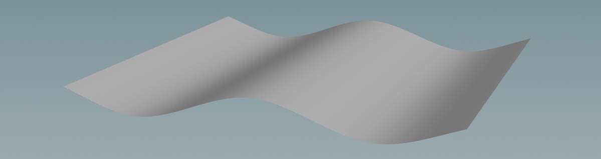
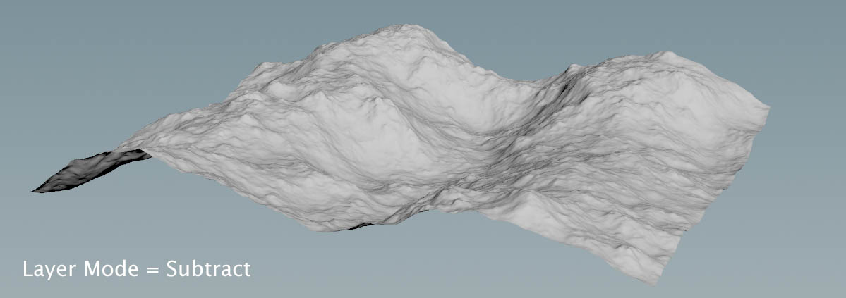
Subtract heightfields 
You have two separate heightfields now: noise and pattern. To combine them, lay down a ![]() HeightField Layer SOP. Connect the first input with the output of the noise node. Link the second input to the output of the pattern node (Terrain to Layer). Since both heightfield share the same layers (
HeightField Layer SOP. Connect the first input with the output of the noise node. Link the second input to the output of the pattern node (Terrain to Layer). Since both heightfield share the same layers (height and mask), the terrains are seamlessly merged.
You will also notice that the entire heightfield is bulged now, because the layer node’s Layer Mode is set to Add. The idea here is to subtract the layers, apply the terraces, and then add the curve again. As a result, only the terraces will be distorted and bulged.
-
Set Layer Mode to Subtract.
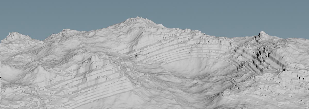
Terracing 
Time to add the terraces. The only changes here concern the Min Height and Max Height parameters to shift the terraces away from the mountain tops towards the ground, and Max Step Size.
-
Lay down a HeightField Terrace SOP and connect its first input with the output of the layer node.
-
Change Min Height to
-80and Max Height to-40. The range, where terraces occur is 40 meters. -
To get more, but thinner layers of rock, decrease Max Step Size to
8.
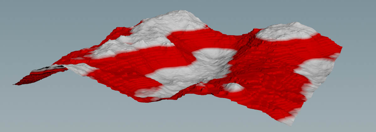
The terraces appears as a red band and you can also apply a mask to restrict the terraces to certain areas.
Add heightfields 
In this step you’ll merge the current terrain with the terraces and the pattern by adding both. This way you restore the terrain’s original shape from the HeightField Noise and only the terraces will follow the wave pattern.
-
Add another HeightField Layer SOP.
-
Connect its first input with the output of the terrace node. Then link the second input_ to the output of the pattern node.
Since the default Layer node is already Add, you will immediately see the result of the merge. If you want a weaker distortion, go to the pattern node’s Height parameter and decrease it, e.g. to 75.
Of course, you can also experiment with different patterns, masks, and everything else Houdini’s toolbox has to offer. To get a linear inclination, for example, choose Linear or Smooth from the pattern node’s curve presets. With Height you can control the amount of inclination.
To get rid of the mask, you can add a ![]() HeightField Mask Clear SOP and terminate the network.
HeightField Mask Clear SOP and terminate the network.
Here’s an example of what you can get with this method.