| On this page |
The ![]() HeightField Scatter SOP creates points on the entire surface according to your settings. And sometimes, there are points and places where you don’t need them. Of course, you can create masks to remove points, but in some cases it’s not so easy to create an appropriate mask. A good example is the area outside a camera frustum. There might also be occasions where you want the scatter points to fade out towards the terrain’s borders.
HeightField Scatter SOP creates points on the entire surface according to your settings. And sometimes, there are points and places where you don’t need them. Of course, you can create masks to remove points, but in some cases it’s not so easy to create an appropriate mask. A good example is the area outside a camera frustum. There might also be occasions where you want the scatter points to fade out towards the terrain’s borders.
This page is part two of a four-pages guide to heightfield scattering:
-
Scattering: SOP illustrates how to prepare your scene.
-
Scattering: Removing points shows methods for controlling the number of scatter points.
-
Scattering: Attributes creates attributes like
pscaleandorient. -
Scattering: Solaris shows how to render your terrain.
For the some examples, VEX scripting is a convenient way to remove unwanted points.
Tip
If you're interested in VEX scripting for heightfields in general, please also take a look at the VEX scripts for heightfields page.
Masking 
Note
There’s already a description on the Scattering: SOP page. This chapter is for your convenience so you don’t have to switch between different pages.
Masking with scatter points on heightfields works in the exact same way as masking in general. To be precise: masks don’t delete points, but instead you define areas where points will appear. Here’s a very basic setup for a scatter mask, assuming that you've already created a ![]() HeightField SOP.
HeightField SOP.
-
Lay down a
 HeightField Mask Noise SOP (or any other mask node) and connect its first input to the output of the heightfield.
 -
Add a HeightField Scatter SOP. Connect its first input with the output of the heightfield. Then, link the second input with with output of the noise mask.
-
Turn on the scatter node’s blue Display/Render flag to see the result.
With the mask node’s default values you will notice a blank spot, while the rest of the terrain is covered with points. A closer look reveals areas of varying density. You can influence point density directly with the noise node’s Amplitude parameter. With
-
values, smaller than
1, you’ll enlarge the blank areas -
a value of
2, for example, you’ll get a very dense structure.
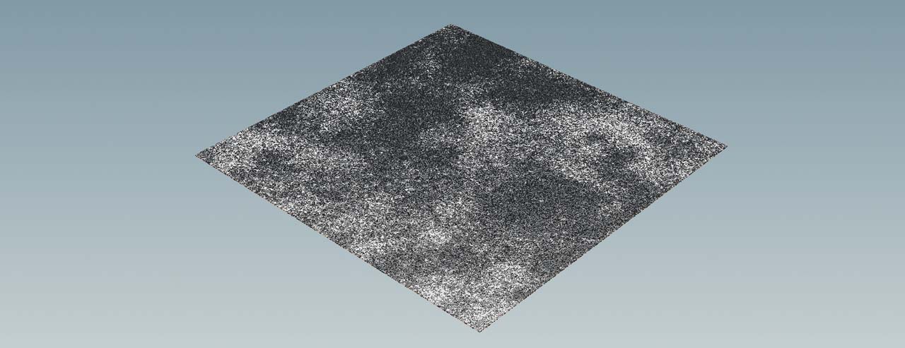
Now, change Element Size. This parameter controls the size of the noise pattern. Smaller values create more noise and also more detail. The image below uses an Amplitude of 1.5 and an Element Size of 200. The result is a realistic point distribution.
Note
You can also apply all the scripts, presented below, to a masked heightfield to further decrease the number of scatter points and create interesting effects.
Scatter Method 
The HeightField Scatter node provides a Scatter Method dropdown menu. The first three entries also support a Mask Layer to control the number of points. The default choice is By Coverage using Mask Layer and you can see the result in the image directly above. When you change Coverage, you can remove or add points.
By Density using Mask Layer works in the same way as the “by coverage” method, but here you have a Density parameter.
Finally, there’s Total Point Count using Mask Layer. Here you set a fixed number of points. Your mask can cover the entire terrain or just a small area of 10%: the number of points will always be the same.
Preparing the nodes 
Since we're dealing with points here, you’ll apply the scripts through a ![]() Point Wrangle SOP instead of a
Point Wrangle SOP instead of a ![]() HeightField Wrangle SOP. The steps to create the appropriate nodes and add the scripts are always the same.
HeightField Wrangle SOP. The steps to create the appropriate nodes and add the scripts are always the same.
-
Add a Point Wrangle SOP and connect its input with the output of the last upstream node.
-
Use copy ⌃ Ctrl + C and paste ⌃ Ctrl + V to add the code to the VEXpression field.
-
Click the
 button to create the custom parameters.
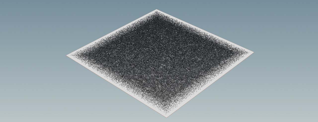
Border points 
The first script removes points from a terrain’s borders within a customizable area. You can also choose, whether you want to create a soft or a hard transition. The points aren’t deleted here, but stored inside a separate group. Just in case you need them again somewhere else. The script
-
adds custom parameters to define the scatter area’s limits in X and Y direction
-
adds a random
offsetto quickly create a smooth transition towards the edges -
compares a point’s position against the borders of the scatter area
-
removes the points within the seam.
Here is the VEX code. As always, this is just one method to write such a script.
float limit_x = chf("limit_x");
float limit_z = chf("limit_z");
float offset = chf("offset");
float seam = fit01(random(@ptnum), -offset, 0);
float border_x = limit_x + seam;
float border_z = limit_z + seam;

if (@P.x > border_x || @P.x < -border_x ||
    @P.z > border_z || @P.z < -border_z) {
        removepoint(geoself(), @ptnum);
}
To apply the above code and delete the border points, do the following.
-
For Limit X and Limit Z enter, for example,
480. This creates a frame with a width of 20 m around a standard heightfield of 1000 m x 1000 m. -
Set Offset to
100to get a smooth transition of scatter points towards the terrain’s borders.
Camera frustum 
A very common method for saving resources is to delete points outside a camera frustum. The concept is basically the same as in the Border points example above. The main difference is that you need a special vector that transforms a position to the normal device coordinates (“NDC”) for a camera. Houdini’s VEX has a built-in function to perform this transformation automatically: toNDC. You can also use this function with a light source instead of a camera. The script
-
takes a custom camera to calculate the transformation
-
lets you define a seam to create a safety buffer around the visible area
-
compares a point’s position against the X and Z components of the NDC vector to identify points outside the frustum
-
deletes the points directly.
The good thing with this script is that it works with animated cameras, because the per-point attributes will be maintained. This avoids that scales or the instance objects themselves change with each new frame.
The problem, however, is that the entire heightfield is removed at a certain position. When you open the Geometry Spreadsheet pane’s ![]() Points mode, you’ll see that the first two entries have several attributes with a value of
Points mode, you’ll see that the first two entries have several attributes with a value of 0. These two entries belong to the heightfield.
To avoid that the script deletes the heightfield by accident, go to the scatter node’s Relaxation section. There, turn off Keep Incoming Terrain. Later you can use a ![]() Merge SOP to bring points and terrain together again.
Merge SOP to bring points and terrain together again.
For this feature you should use two Attribute Wrangles, because you must read a camera path and doing this for every scatter point is not very efficient. It’s better to fetch the camera with a Detail Attribute Wrangle. For convenience reasons you’ll also create a Seam parameter here. Add it to the network before the point wrangle that removes the points!
This is the VEX code for the detail wrangle:
s@campath = chs("camera_path");
f@seam = chf("seam");
Click the ![]() Creates spare parameters for each unique call of ch() button to create the parameters.
Creates spare parameters for each unique call of ch() button to create the parameters.
-
In the viewport, find a nice view of the terrain.
-
In the upper right corner of the viewport, you can see two menus. Open the No cam menu and choose New Camera. This will create a
cam1camera object on the obj level. -
For Camera Path, enter
/obj/cam1. This is the location of the newly created camera from step 2. -
Change Seam. With
0, you can delete points exactly along the outlines of the frustum. With values, greater than0, you create a safety buffer outside the frustum.
On the point wrangle, enter the following VEX script:
vector camera_ndc = toNDC(s@campath, @P);

float border_min = 0.5 - f@seam;
float border_max = 0.5 + f@seam;

if (camera_ndc.x + seam < 0 || camera_ndc.x - f@seam > 1 ||
    camera_ndc.y + seam < 0 || camera_ndc.y - f@seam > 1) {
        removepoint(geoself(), @ptnum);
}
In the image below, the particles outside the camera frustum are displayed in red to make the result more obvious.
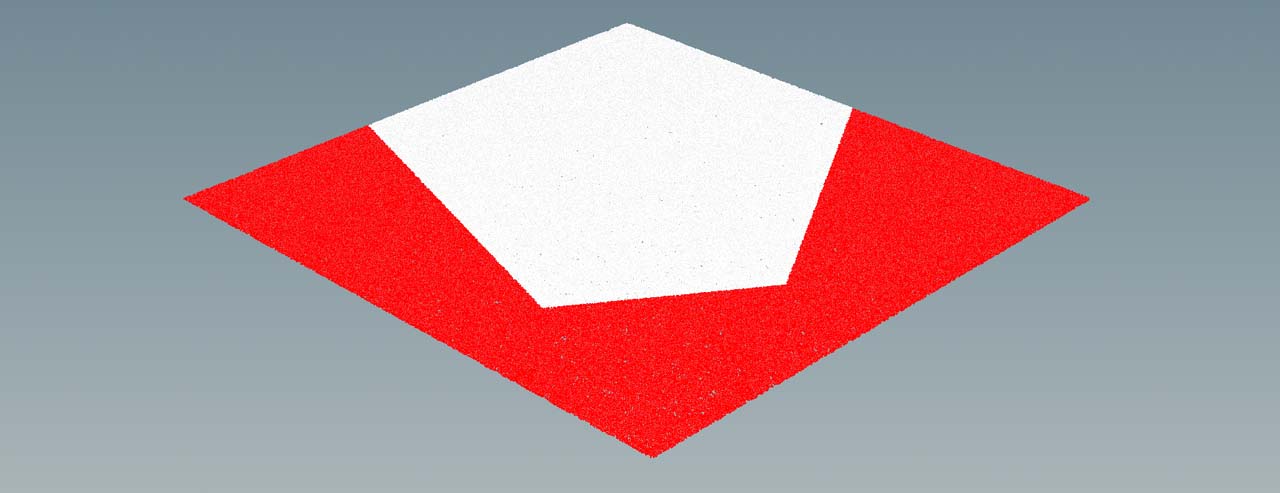
Tip
You can also store the particles outside the frustum to a group instead of deleting them.
Replace removepoint(geoself(), @ptnum) with @group_outsidepoints = 1;
Camera distance 
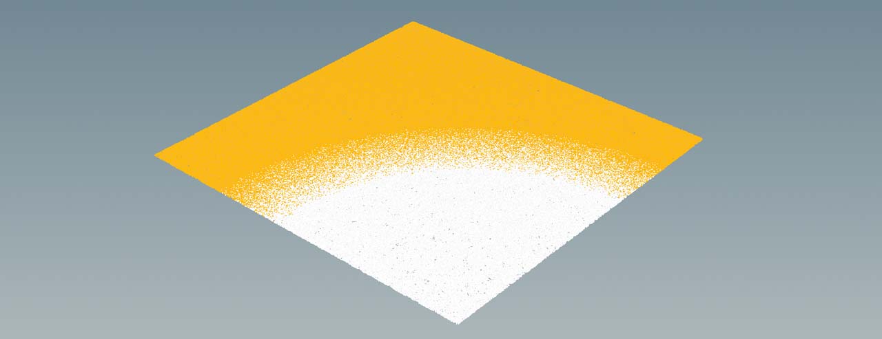
You can also remove points based on a point’s distance from a camera. Instead of drawing a mask, you can just increase distance with a slider and get rid of unwanted points. Note that you’ll get a circular or arc-shaped border. The script
-
lets you define a custom distance threshold
-
queries the camera’s position in world space
-
calculates the distance between the camera and the scatter points
-
removes the points beyond the given threshold
-
uses the custom Seam parameter to create a soft transition.
Since we're again dealing with positions, it can happen that the heightfield itself disappears. To avoid this, turn off the heightfield node’s Keep Incoming Terrain option.
As with the camera frustum you also need a detail wrangle to initialize some parameters an values. Here’s the script that also includes all relevant parameters. The 4@camera_matrix calculates a 4×4 matrix. Doing this for every scatter point would drastically slow down the process. By defining @camera_matrix as a one-time detail attribute, the distance calculation becomes really fast.
The script calculates the camera matrix with the help of the optransform function. This, more advanced approach is necessary to compensate for a camera-specific offset.
// Calculate a 4x4 transformation matrix
4@camera_matrix = optransform(chs("camera_path"));

f@dist_threshold = chf("distance_threshold");
f@seam = chf("seam");
Click the ![]() Creates spare parameters for each unique call of ch() button to create the parameters.
When you create a camera from the viewport in a fresh scene, Camera Path is
Creates spare parameters for each unique call of ch() button to create the parameters.
When you create a camera from the viewport in a fresh scene, Camera Path is /obj/cam1. The Dist Threshold value for the image below is 800 and Seam was set to 200 to achieve a smooth transition.
And here’s the script for the point wrangle:
vector camera_position = set(0,0,0) * 4@camera_matrix;

float seam = fit01(random(@ptnum), f@seam, 0);
float point_distance = distance(@P, camera_position);


if (point_distance > f@dist_threshold - seam) {
    removepoint(geoself(), @ptnum);
}
In this image, the points outside Dist Threshold are displayed in orange.
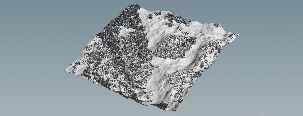
Occluded points 
The Camera distance script lets you delete points based on their distance to a camera. This is helpful, but not always effective. A more selective method can delete occluded points. The script sends out a ray from the camera to test for intersections with the terrain. Points that are are occluded by mountains or other geometry will be deleted.
Note
For this method you need a ![]() HeightField Noise SOP that creates mountains.
HeightField Noise SOP that creates mountains.
The script
-
lets you choose a camera object
-
queries the camera’s position in world space
-
calculates the camera’s direction
-
calculates a point’s distance from the camera
-
sends out rays based on the distance and direction to find occluded points
-
uses the
tagattribute to prevent the heightfield itself from disappearing.
As before, you need a detail wrangle and a point wrangle. Here’s the detail code:
// Calculate a 4x4 transformation matrix
4@camera_matrix = optransform(chs("camera_path"));
Click the ![]() Creates spare parameters for each unique call of ch() button to create the parameters.
In a fresh scene, the default Camera Path is
Creates spare parameters for each unique call of ch() button to create the parameters.
In a fresh scene, the default Camera Path is /obj/cam1.
To make the frustum and distance point removal scripts work correctly, you've deleted the terrain. For this method, the heightfield is essential, because you need the “geometry” to calculate the occluded areas. This means that you must exclude the two points that define the heightfield. One method is to use the tag attribute that’s created by the scatter node. The heightfield points don’t carry this attribute and you can check if it’s empty.
vector camera_position = set(0,0,0) * 4@camera_matrix;
vector camera_direction = normalize(camera_position - @P);
float camera_distance = distance(@P, camera_position);

vector pos, uvw;

int hit_test = intersect(0, @P, camera_direction * camera_distance, pos, uvw);
if (hit_test != -1 && s@tag != "") {
    removepoint(geoself(), @ptnum);
}

if (hit_test != -1) {
    removepoint(geoself(), @ptnum);
}
Here you can see a terrain with occluded points removed.