| On this page |
The introduction’s Generating a height field from scratch chapter explains how to create a complete terrain with hills and valleys. However, sometimes you only need a single hill or just more control where mountains should appear. You can, for example, use such a solitary mountain as a patch and merge it with another heightfield.
One solution is to draw a custom map, load it to Houdini and extrude it. The advantage is that you can directly add features by combining different layers inside an image processing software. The Heightfields from maps pages describes in detail how to create terrains from images. If you have to change something, you must redraw the map.
You can also project an object onto an empty heightfield, for example a cone or any other geometry that looks similar to a mountain. Then you can distort and erode the object to make it look natural.
Another method for creating a mountain is to open the Terrain FX shelf tool and click ![]() Terrain: Mountain. This tool uses heightfield projection.
Terrain: Mountain. This tool uses heightfield projection.
Below, you can also find a workflow that scatters objects over an irregular area and uses a few lines of VEX code to create a mountain.
Finally, it’s possible to use a certain type of noise from the ![]() HeightField Noise SOP and draw a mask to create a solitary peak.
HeightField Noise SOP and draw a mask to create a solitary peak.
Masking method 
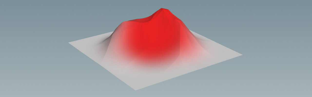
You can create a mask through a ![]() HeightField Draw Mask SOP, a HeightField Mask Noise SOP or both. The mountain appears inside the red areas of the mask.
HeightField Draw Mask SOP, a HeightField Mask Noise SOP or both. The mountain appears inside the red areas of the mask.
-
On the obj level, create a
 HeightField OBJ. Double click the new node to dive inside, where you find the actual object.
 -
Lay down a HeightField Draw Mask SOP and connect its input with the heightfield’s output.
-
Hover the mouse cursor over the viewport and press Enter. You're now in drawing mode.
-
Press and hold the
 to draw an arbitrary shape onto the plane. Press
⎋ Esc when you're finished and leave the drawing mode.
to draw an arbitrary shape onto the plane. Press
⎋ Esc when you're finished and leave the drawing mode. -
On the mask node’s Masking tab. increase Blur Radius to
50to get smooth borders.
Tip
For a more natural and eroded shape without a hard-edged plateau, set Blur Method to Box Blur.

Remapping 
To turn the mask into a mountain, you can remap the heightfield.
-
Add a
 HeightField Remap SOP to your network.
 -
Connect the remap node’s first input with the output of the heightfield. The second input is linked to the output of the mask.
-
Increase Output Max to elevate the masked area. Start with a value of
400to see a decent effect. The blurred edges create a smooth base.
Now you can apply any other heightfield node to shape the mountain, typically noise, distortion and erosion. Distortion is of particular interest, because it adds structure to the vertical “walls” of the mountain.
You can also use the mask you've created to shape the mountain, to prevent the ground from being eroded. On the Main and Advanced tabs you can find Erodability and Removeal Rate Masks. Open their associated drop-down menus and choose Mask on. Then, substitute their default entry with mask.
Scatter method 
Instead of a mask you can also use any geometry and turn it into heightfield. The magic word is scattering, a method that is explained in detail on the Heightfield scattering page. Here you’ll learn how to create an interesting base shape for a mountain.
The following method might appear a bit cumbersome and there are definitely faster and more convenient ways to create a mountain. But, the example is a concept that illustrates how to achieve a goal with alternative paths. It’s also a very flexible method that has lots of knobs for customizing and randomizing your terrain.
The idea is to define an irregular polygon object that serves as a ground that is covered with points. Then you scatter a base object, e.g. a tube, across the points. The distance of each tube from the ground object’s position determines its height: tubes, closer to the center are high, those near the object’s borders are low. What you get is a mountain shape that you can project onto an empty heightfield.
Mountain base 
The base object’s size and shape defines the foot of the mountain.
-
On the obj level, create a
 Geometry OBJ. Double click the new node to dive inside.
 -
Add a
 Circle (Polygons) SOP. The circle will be deformed to create the irregular structures.
 -
Right now, the circle is oriented along the ZX plane. From the Orientation dropdown menu, choose ZX Plane.
-
Turn on Reverse to make the circle’s normals point upwards.
-
Uniform Scale is the first parameter for customizing the mountain. Considering that a default heightfield is 1000 m by 1000 m, this value shouldn’t be too small. Start with
300to create a disk with a diameter of 600 m. -
Increase Division to
200to get more edges and jags.
Deformation 
Noise is a common method to add variation to masks, object, point clouds, maps, etc. In this scene, noise will deform the base object.
-
Add an
 Attribute Noise SOP and connect its input with the output of the circle node. You’ll now see a disk with colored stripes.
 -
The colors come from the Attribute Names parameter’s default
Cdentry. Change the name toPfor “position”. -
Next to Attribute Names you can see XYZ buttons. Deformation should only be applied in XZ direction. Click the Y button to turn off the circle’s Y direction.
-
Go to the Noise Value section’s Amplitude and change the value to
200. Higher values create more distortion. -
The Noise Pattern section provides an Element Size parameter to control the amount of noise. Set the value to
250for a moderate distortion.
Note
You can also use a ![]() Point Jitter SOP to randomize the ground object’s shape. The result will be pretty much the same.
Point Jitter SOP to randomize the ground object’s shape. The result will be pretty much the same.
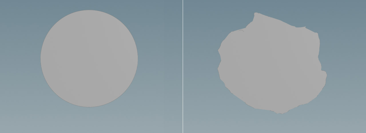
Here’s an image that shows the transformation from a circle to a polysurface.
Translation 
You can also see that the circle was displaced and its center is no longer in the scene’s origin. This will, of course, affect the position of the mountain, so it’s better to reset the object to the scene origin.
In contrast to vertex, point or primitive attributes, a detail attribute is a property of an object itself, not its components. An example: if you say “the ball is red” then you're talking about a detail attribute, because you mean the entire ball, not the individual components it’s made from.
For the reset you need three lines of VEX code (yes, VEX scripts can be very short). It’s possible to use a ![]() Transform SOP and click the Move Centroid to Origin to reset the object, but you always have to click this button when you change the circle’s shape or scale. Therefore it’s better to have an automatic position update.
Transform SOP and click the Move Centroid to Origin to reset the object, but you always have to click this button when you change the circle’s shape or scale. Therefore it’s better to have an automatic position update.
-
Add an
 Attribute Wrangle SOP and connect its first input with the output of the Attribute Noise SOP.
 -
On the Code tab, set Run Over to Detail (only once).
-
Go to the VEXpression input field and enter
vector base_pos = getbbox_center(0);

f@base_pos_x = base_pos.x;
f@base_pos_z = base_pos.z;
The code calculates a position vector
base_pos. To do this, you get the center of the bounding box around the deformed circle. The(0)part indicates that the function takes the object from the wrangle’s first input. Then the script extracts the X and Z components ofbase_posand stores them in appropriate attributes:@base_pos_xand@base_pos_z. -
Add a
 Transform SOP and connect its input with the wrangle’s output.
 -
On the Translate.X parameter, enter
-@base_pos_x. -
For Translate.Z, type
-@base_pos_z.
Now, the deformed circle will always sit exactly in the scene’s origin.
Scatter points 
Scattering is the process of distributing objects over a surface or another object. Here you’ll be scattering a tube and control its size with the help of a customized pscale attribute.
-
Lay down a
 Scatter SOP and connect its input with the output of the transform node.
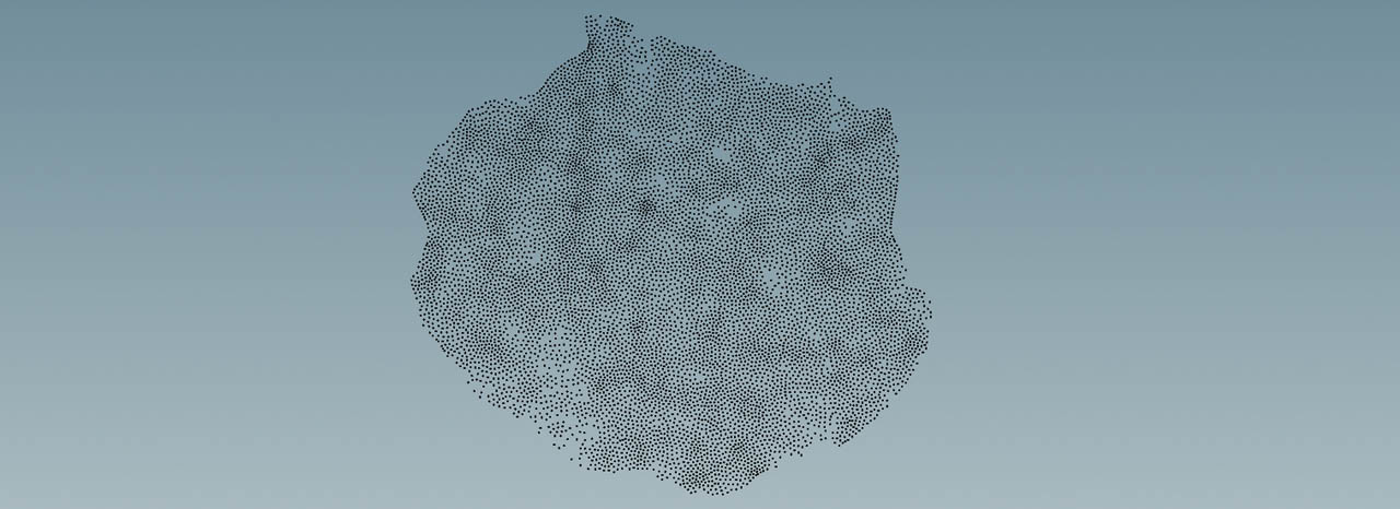
 -
Open the Options tab and go to Force Total Count. This parameter determines the number of scatter points and finally the number of tubes. Enter a value of
10000to get a structure that is dense enough to create a solid object. -
For a less random distribution of points, increase Options ▸ Relax Iterations to
100.
Instance object 
The instance object in this example is a tube, but you can use any other object as well.
-
Add a
 Tube SOP.
 -
Turn on End Caps to create a closed object.
-
The lower cap should sit exactly on the heightfield’s zero level. Go to Center.Y and enter
0.5. This is half the tube’s Height value of1. -
Put down a
 Copy to Points SOP. Connect its first input with the output of the tube, and the second input with the output of the scatter node.
When you turn on the copy node’s blue Display/Render flag, you will see 10000, rather small, tubes with the same height and radius. Another VEX script lets you scale the tubes and create the outlines of a mountain.
Scale control 
To change the height of each instance based on its distance to the distorted circle’s center you need another VEX script. This script also changes the tubes' diameter and contains custom parameters. A ch[type] statement introduces custom parameters,
-
Add a new Attribute Wrangle SOP and place it between the scatter and copy nodes to connect its first input.
-
Copy ⌃ Ctrl + C the code below and paste ⌃ Ctrl + V it to the VEXpression input field.
vector peak_position = set(chf("offset_x"), 0, chf("offset_z"));

float base_scale = chf("base_scale");
float dist_scale  = exp(chf("steepness") * distance(peak_position, @P));

@scale = set(base_scale, fit(noise(@ptnum), 0, dist_scale, 0, chf("height")), base_scale);
-
Next to VEXpression click the
 Create spare parameters… button to create the custom parameters.
 -
Use the following values for the custom parameters
-
Set Base Scale to
20to create overlapping tubes. -
Increase Height to
30. This is the maximum height of the mountain. -
With Offset X and Offset Y you can shift the mountain’s peak.
-
Lower Steepness values create a more natural mountain. This parameter is very sensitive, so start with a value around
0.007.
-
Here’s the explanation of the VEX code.
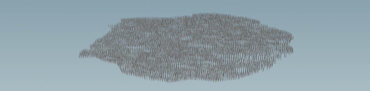
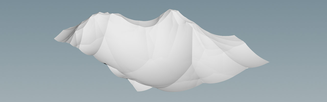
With Offset X set to 50 and Offset Z set to 200, you should get a mountain like in the image below.
Projection 
Now you can project the geometry onto the empty heightfield and apply some blur to seamlessly blend both objects.
-
Add a
 HeightField Project SOP and connect its first input with the output of the HeightField SOP. Link the second input to the output of the Copy to Points SOP.
 -
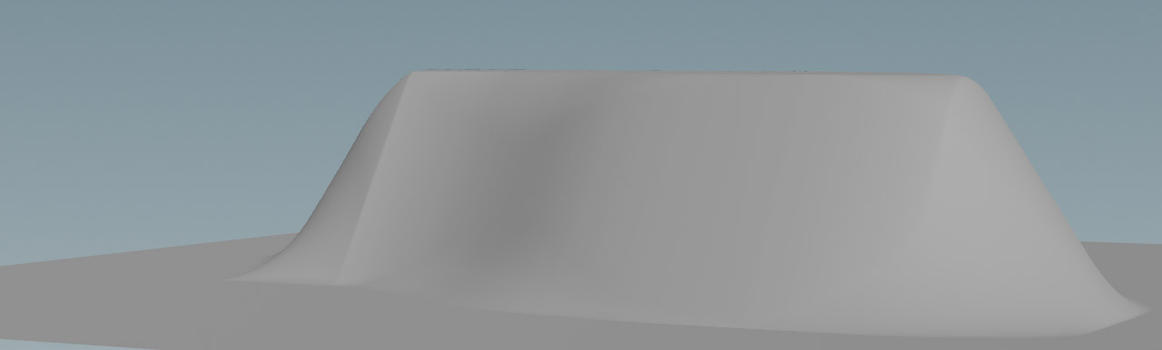
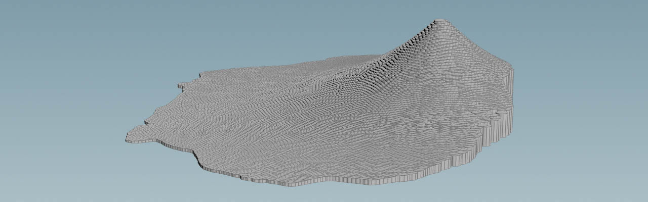
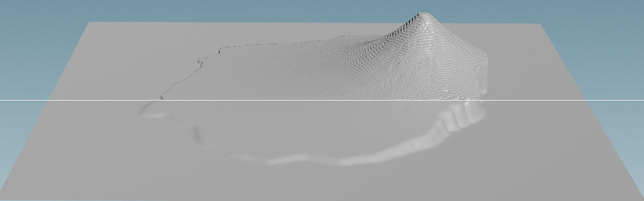
The result is still a bit “blocky” (upper part of the image below), but you can smooth the surface with a
 HeightField Blur SOP (lower part of the image).
Hilly landscape 
The scattering method is not only good for a single mountain or hill, but also for complete landscapes. You can even use already existing point clouds with exactly defined positions to place the hills where you want them to appear. As scatter objects you can use cones, hemispheres or any other geometry - and combinations of different shapes.
With just a few scatter points and cones, for example, it’s possible to create a mountain chain with summits and patch it to a base terrain.
Noise and mask 
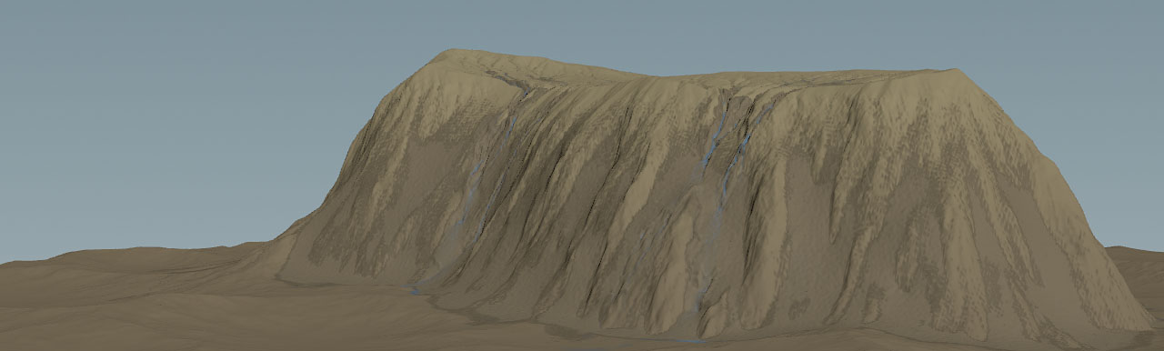
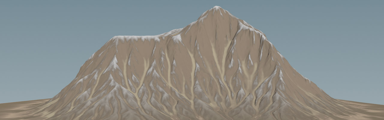
The last method we want to discuss, uses a HeightField Noise SOP and mask. The idea ist to scale and shift the noise in a way to get just one or two peaks. Then you draw a mask to restrict the creation of the terrain to a certain area, and blur the mask to make the mountain fade out. You can improve the result by distorting and eroding the mountain as shown in the image below.
Of course, you can use the HeightField Noise SOP’s default Noise Type called Sparse Convultion, However, to get a more natural appearance with peaks and ridges, change the dropdown menu to Worely Cellular F1.
-
On the noise node, change Amplitude to
400. -
Increase Element Size to
600. -
For Offset, enter
0, 0, 500to shift the noise pattern along the Z axis. -
If not already done, go to Noise Type and choose Worely Cellular F1.
Masking 
Now you’ll draw a mask to fade out the terrain and create a mountain you can then use as a patch.
-
Add a HeightField Draw Mask SOP and place it between the HeightField and HeightField Noise SOPs. Connect the mask’s output with both inputs of the noise node.
-
Hover the mouse over the viewport and press 2 to see the terrain from top view. Press H to center the heightfield.
-
Now, press Enter to turn on the node’s drawing mode. Use the
to draw a mask onto the heightfield grid. The mask doesn’t have to be a perfect circle and it can even be irregular. You’ll see a red area with surface structures inside. -
Leave the drawing mode with ESC.
-
On the mask node, increase Blur Radius to
150or more to get smooth edges.
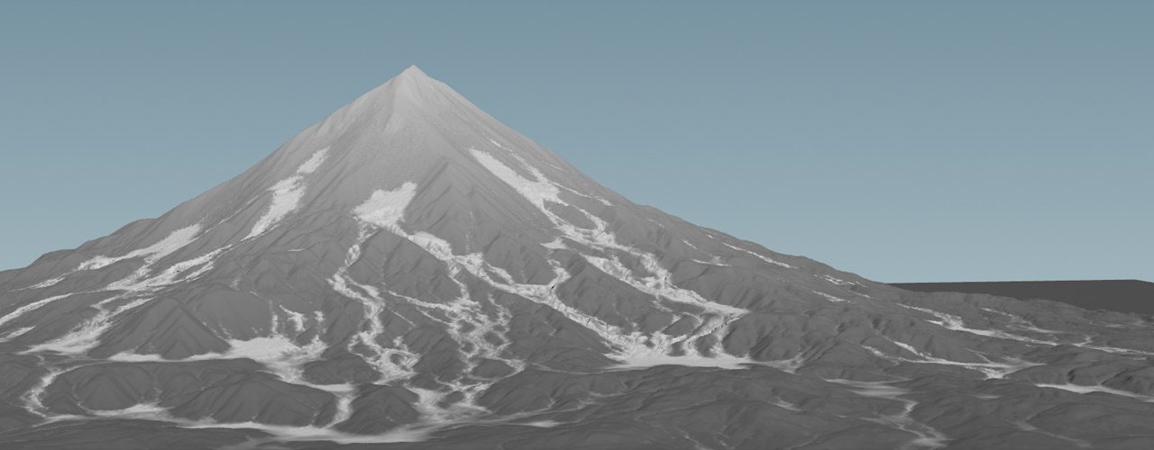
Here you can see the result with the mask still visible.