| On this page |
Imagine a situation where you need a fast method to create large amounts of water. A particle-based fluid simulation is perhaps computationally too expensive, and an ocean surface is most probably not flexible enough. This is a typical scenario for Houdini’s Shallow Water Solver, because it fills the gap between highly-detailed simulations and ocean spectra representing a water surface. The Shallow Water Solver is capable of simulating flowing water and ýou can create:
-
ripples and non-breaking waves
-
ponds and puddles
-
water running over cracks and surface irregularities
-
stylized water or water surfaces in distant areas
-
fast flooding of large areas
-
streams and trickles
You can consider the Shallow Water Solver as an extension for Houdini’s heightfields. From a technical perspective, a heightfield is a 2D grid with height (or other) information stored at its grid points as a so-called layer. The height layer is one of the principle layers with heightfield. Typical layers with heightfields are sediment, flow or debris. These types of layers shape the terrain, for example by removing or adding material. In fact you're manipulating the terrain’s height information to achieve a certain look. The Shallow Water Solver works according to same principle and adds a water layer to the terrain.
Aside from height, there’s also a principle mask layer. A mask limits an effect to a user-defined area. Houdini’s heightfields provide a wide range of nodes to draw masks, calculate them from the terrain’s topology or an object’s volume. Masks are an essential concept in conjunction with the Shallow Water Solver, as they define where water is sourced or drained.
Limitations 
You can use the solver for large-scale simulations, but also for small-scale effects as listed above. The solver is very fast, but often suffers from stability problems, especially at high resolutions or high propagation speeds. This is typically manifested in jitter, spikes or disappearing heightfield voxels.
-
The solver can’t simulate secondary water effects like splashes or spray.
-
Breaking waves are not possible.
Heightfield setup 
You need a heightfield to make the Shallow Water Solver work. You can read more about such a basic scene on the heightfields page. Here, you’ll only get the fundamental explanations to get you started.
-
On the obj level, press ⇥ Tab to open the tab menu. There, enter
hfand choose HeightField to create a new Geometry OBJ. Double-click the geometry node to get access to the
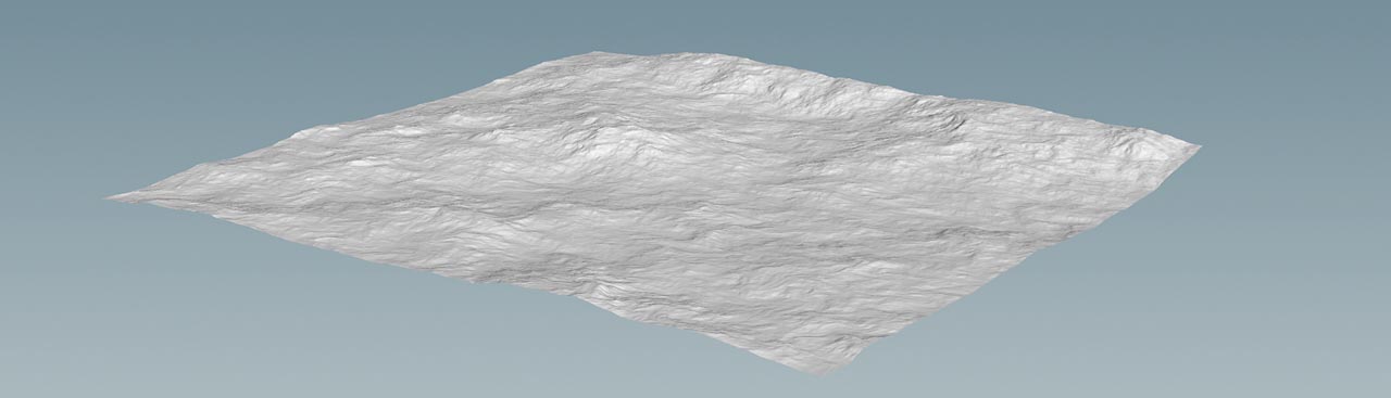
  HeightField SOP inside. In the viewport, you can see a flat plane representing the heightfield grid with empty
 heightandmasklayers. -
To get more surface detail, decrease Grid Size to
1. Note that this value is also relevant for the solver. -
Add a
 HeightField Noise SOP and connect its first input with the output of the heightfield grid. This nodes adds height information and creates a landscape with mountains and valleys.
Shaping the terrain 
The terrain’s topology has strong influence on the behavior of the water. However, scenes with extreme height differences might not look good in the end. Here you’ll be working with a relative flat landscape. On the HeightField Noise SOP, set Amplitude to 200 to create smooth hills. Also, increase Element Size to 600. This parameter changes the scale of the fractal pattern and with higher values, you can reduce the amount of peaks.
You can also make the seabed more interesting by adding more surface structures. A good way to do this is to add a ![]() HeightField Distort by Noise SOP. Connect its first input with the output of the upstream noise node. Then, set Amplitude to
HeightField Distort by Noise SOP. Connect its first input with the output of the upstream noise node. Then, set Amplitude to 20. This parameter controls the strength of the curl noise that deforms the terrain.
Sources 
The Shallow Water Solver requires a source layer to define where the water originates - and the source is essentially a mask. We recommend that you read the heightfield guide’s Masking pages. There you’ll get a comprehensive overview how to create, combine and manipulate masks. On the VEX scripts for heightfields page you can also find several methods to create custom masks with scripting, for example rings or ovals.
Note
You can also make the water disappear through a sink.
-
Lay down a
 HeightField Paint SOP and connect its input with the output of the distort node.
 -
The most interesting parameter on the paint node is FG Value, because it controls how much water will be sourced. With values greater than
1, you can create more water per unit time. For this project, enter a value of0.5.A value of
1is the base amount of water being sourced. A value0.5will only source 50% of the base amount, and with2the amount will be doubled. -
Hover the mouse over the viewport and press 2 to switch to top view. Then, press Enter to turn on the draw mode. A red sphere indicates the size of the paintbrush. Use the
 to change the size of the brush.
 -
With
 pressed, draw over the terrain. The viewport grid will help you to identify deeper areas of the landscape. Draw a pattern that looks similar to the image below.
 -
Press ESC to leave the draw mode.

Refining the mask 
Right now, the mask is just a red area without structure. To make things more interesting, you can add a ![]() HeightField Mask Noise SOP and connect its first input with output of the paint node. The node creates a mask with spots of different size and “opacity”.
HeightField Mask Noise SOP and connect its first input with output of the paint node. The node creates a mask with spots of different size and “opacity”.
When you set Combine Method to Subtract, everything outside the painted area will be removed and you also create spots inside the painted area. With Amplitude you can directly influence the amount of water being sourced. Set it to 0.5 to get more variation. Element Size changes the size of the red spots. With 100 you can break the pattern, because the spots become smaller.

Creating a source layer 
So far, you've only worked on the mask layer. To convert the mask into a source layer you need a ![]() HeightField Copy Layer SOP. Connect the node’s input with the output of the noise mask. Then, go to the copy node’s parameter set. For Destination, enter
HeightField Copy Layer SOP. Connect the node’s input with the output of the noise mask. Then, go to the copy node’s parameter set. For Destination, enter source. Now you've transferred the information to a new layer that can be evaluated by the Shallow Water Solver to create water in the red areas.
It also makes sense to reset the mask layer with a ![]() HeightField Mask Clear SOP. Add it to the network and set
HeightField Mask Clear SOP. Add it to the network and set Layer1 to mask. This node does not delete the mask layer, but sets all values to zero instead.
The solver 
You've got everything you need to flood the terrain with water and you can lay down a ![]() Shallow Water Solver SOP. Connect its first input with the output of the last upstream node. It’s often a good idea to perform a simulation with the default values to see what you might want to change.
Shallow Water Solver SOP. Connect its first input with the output of the last upstream node. It’s often a good idea to perform a simulation with the default values to see what you might want to change.
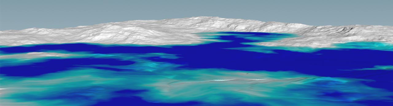
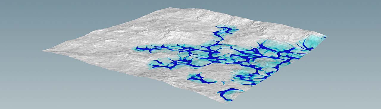
The most obvious observation is perhaps that the water is hardly visible and it’s therefore difficult to evaluate the results. To change this, open the solver’s Output tab. From the Visualization dropdown menu, choose Color by Water Layer. You can now see blue strings on a turquoise area.
The water also immediately starts to fill the basin, but it’s very shallow. Another issue is that the water hardly propagates over the terrain.
Resolution 
On the Simulation tab, you can find a Voxel Size Scale parameter that corresponds with the heightfield’s Grid Spacing. A convenient workflow is to use the same value for both parameters. If you decide to work with different values, note that the solver’s parameter overrides the terrain’s value.
High-resolution terrains/simulations can also lead to instabilities. The resolution, however, strongly depends on the terrain’s size. With large areas, you normally work with values between 0.5 and 2. A small terrain, for example with a size of 20 m by 20 m, requires values around 0.025 or less to get enough detail.
If the fluid simulation suffers from stability problems that can’t be resolved with damping and velocity limits, consider increasing Voxel Size Scale.
Source scale 
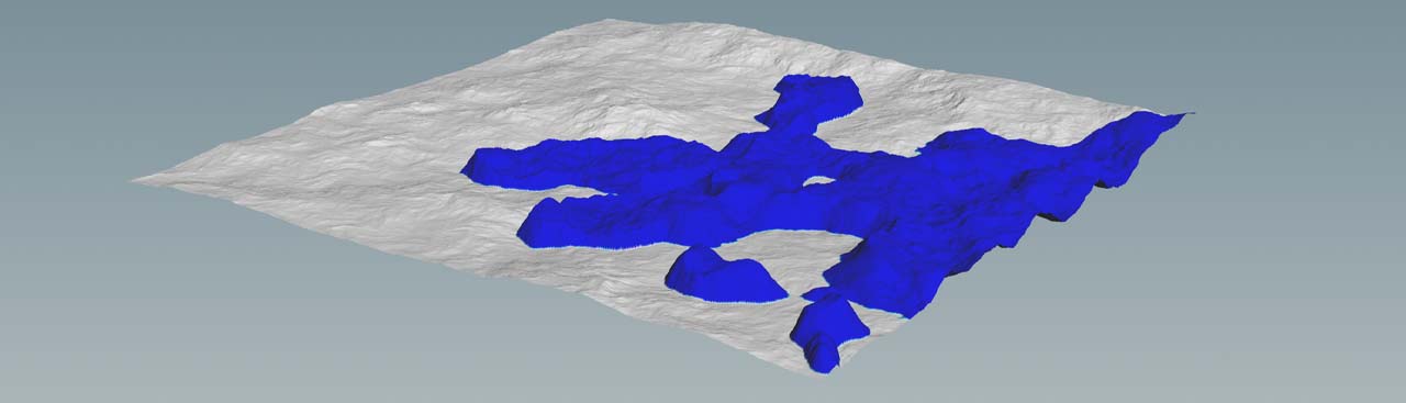
Increasing Source Scale is an effective method to get more water. The parameter is a multiplier for the values in the source layer. If you apply a high value of 100, you’ll get a massive initial water volume. The top of the volume also shows an irregular structure. The reason is that the terrain is considered here, because the mask is semi-transparent. With a completely opaque mask, the top would be even.
If you don’t want a mountain-like water volume as the simulation’s initial state, you can animate the parameter. Let’s assume you want to start sourcing at frame 0 and have full “power” at frame 100.
-
On the Playbar, drag the playhead to frame
1. -
Set Source Scale to
0and Alt +-click the parameter to create an animation key. -
Move the playhead to frame
100. -
Increase Source Scale to
15and create another key.
On the solver, press Reset Simulation to start a new pass. Now, the water rises slowly, but it has edges and the structure of a lava field.
Time scale 
You can use the Time Scale parameter on the Source tab to control the water’s propagation speed. The terrain is quite large and a scale of 5 appears appropriate. You might have noticed some instabilities as well. Before you start to increase the number of simulations steps on the Simulation tab, always try to stabilize the simulation with the parameters of the Setup tab. An effective method is to add moderate viscosity to the fluid by setting Velocity Diffusion to 0.3.
Speed limits and damping 
Another, even better way, uses the parameters of the Speed Limits section. Turn on Max Wave Speed and set its value to 2. This will clamp all waves with higher velocities to this value. You will see that the overall behavior is much better now and that you can really flood the terrain with water.
You should also consider to introduce a Damping Layer, because it’ll improve the quality of the simulation near the borders. Turn on Enable Damping Layer and increase Layer Size to 30. This parameter helps to make waves disappear at the borders. If this parameter is not high enough, you might see waves being reflected at the borders and rolling back into the water. For a large terrain, a value between 20 and 50 is often enough. The four Axis toggles let you decide which borders should be affected by the damping layer. In most cases you’ll be using the default choice.
Sinks 
If you want to make the water disappear, you can create a sink layer. Like its source counterpart, this layer also originates from a mask. You can use the same nodes and techniques for the creation of source and sink layers. However, a sink can’t work without a source.
The water layer 
The water layer you get from a simulation is part of the heightfield. The Shallow Water Solver differentiates between absolute and relative water layer values. To change between the modes, go to the Output tab. When Output Water Height is Absolute is:
-
turned on,
watercontains the location of the water surface -
turned off,
watercontains the height of the water column at each voxel
When you turn on Output Terrain Includes Water Height, the Water Layer is added to the Seabed Layer. In the viewport, the water appears elevated from the underlying collision surface. When you turn it off, the water appears as a thin colored film over the collision geometry. This mode can be interesting if you want to create a wetting effect.