Flow fields are available with the ![]() Heightfield Erode SOP,
Heightfield Erode SOP, ![]() HeightField Slump SOP, but also a separate
HeightField Slump SOP, but also a separate ![]() HeightField Flow Field SOP. You can, for example, use the fields as distortion layers for the
HeightField Flow Field SOP. You can, for example, use the fields as distortion layers for the ![]() HeightField Distort by Layer SOP. Another field of application for the layers is masking. Or you can use the fields for scattering rocks, trees, and other landscape elements. Flow fields are interesting for all kinds of erosion where material is removed and transported.
HeightField Distort by Layer SOP. Another field of application for the layers is masking. Or you can use the fields for scattering rocks, trees, and other landscape elements. Flow fields are interesting for all kinds of erosion where material is removed and transported.
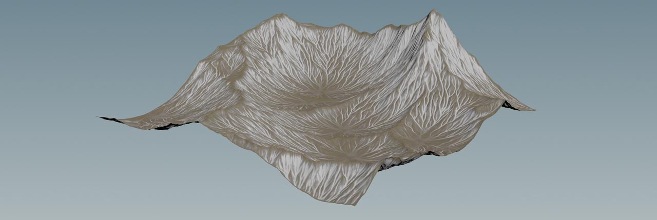
When you calculate a flow field, you’ll get two layers: flow and flowdir. The first layer represents the cumulative material flow in voxel space. The second layer shows the average direction of flow at each voxel. The flowdir layer doesn’t contain any height information. The image below shows the flow layer (white) of an erosion node.
Example: Erosion channels 
The following example illustrates how to use a flow field to create deep erosion channels through distortion.
Note
All explanations and examples use a very basic terrain, consisting of a ![]() HeightField SOP and a
HeightField SOP and a ![]() HeightField Noise SOP to get some mountains and rocky structures. To get enough detail, set the heightfield node’s Grid Spacing to
HeightField Noise SOP to get some mountains and rocky structures. To get enough detail, set the heightfield node’s Grid Spacing to 1.
For more information on how to work with this fundamental setup, please read the Generating a heightfield from scratch introduction.
-
On the HeightField Noise SOP, turn off Center Noise, because you’ll be using a Worley noise for the terrain that already comes with a vertical offset.
-
Set Amplitude to
400. This will slightly decrease the height of the mountains. -
Go to the Noise Settings section. From the Noise Type dropdown menu, choose Worley Cellular F1. You will now see a mountain range with sharp peaks and ridges.
-
Lay down a
 HeightField Distort by Noise SOP and connect its first input with the output of the noise node. This node breaks up the regular fractal and creates small rocky structures.
 -
To get more detail, change Element Size to
75.
Flow 
Here, you’ll be creating the flow field that will later control the amount of erosion. You can consider the HeightField Flow Field SOP a modified ![]() HeightField Slump SOP. This node simulates how debris and lose material behaves when it’s sliding down a hill and there’s a separate chapter about this node.
HeightField Slump SOP. This node simulates how debris and lose material behaves when it’s sliding down a hill and there’s a separate chapter about this node.
-
Lay down a HeightField Flow Field SOP and connect its input with the output of the distort node. After a couple of moments you’ll see a red mask.
-
Go to the Flow tab and change Slump Mode to Smooth. With this mode, the water spreads out in every possible direction.
-
Change Rain Amount to
0.4to simulate stronger precipitation. The mask now becomes slightly denser, because there’s an increased probability for raindrops to cover larger areas of the terrain. With Rain Density you can also simulate different types of rain form normal to intense.
Flow layers 
As mentioned in the introduction, the flow field nodes creates several layers that represent how water spreads over the terrain, but there’s also a water layer itself. The water layer is directly affected by the node’s Rain Amount and Rain Density and where the water collects in the terrain.
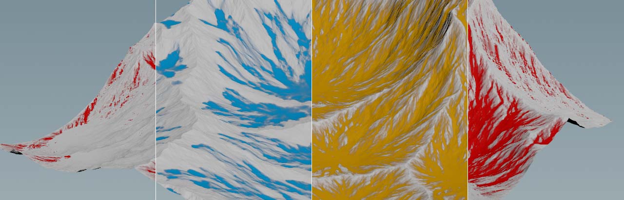
You can use a ![]() HeightField Visualize SOP to make the flow field layers visible. Just use the visualize node’s Layer parameters and apply a Color. The image shows the flow field node’s layers:
HeightField Visualize SOP to make the flow field layers visible. Just use the visualize node’s Layer parameters and apply a Color. The image shows the flow field node’s layers: flowdir.x, water, flow and flowdir.z.
Distortion 
In this step you’ll use the flow layer to scale the displacement of the terrain to control the size and depth of erosion channels.
-
Add a HeightField Distort by Layer SOP and connect both inputs with the output of the flow field node. The second input makes the existing layers available to all relevant parameters.
-
Open the Scale Field parameter’s dropdown and choose
flow. This field will be used to displace the terrain inside the masked area. -
Set Displace Scale to
2to create deeper and more pronounced channels.
If you still think the channels are too deep or show tiny spikes, you can add a ![]() HeightField Blur SOP after the distortion node. Set Radius to
HeightField Blur SOP after the distortion node. Set Radius to 0.5 or 1 to keep as much detail as possible.
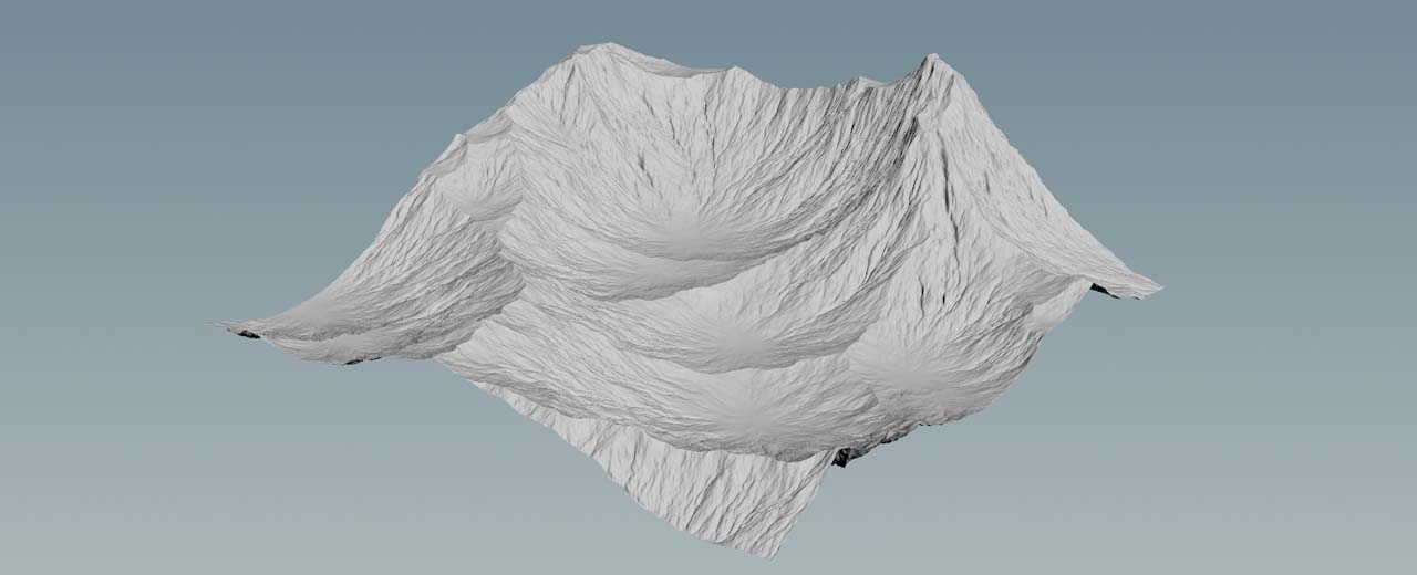
And to get rid of the mask, terminate the network with a ![]() HeightField Mask Clear SOP. The default entry for Layer 1 is already
HeightField Mask Clear SOP. The default entry for Layer 1 is already mask, so you don’t have to change anything. Then turn on the node’s blue Display/Render flag to see the final result.