| On this page |
When loose stones and rocks become unstable, they slide down for a rather short distance and form out deposits in lower areas. The ![]() HeightField Slump SOP lets you simulate and fine-tune this process through a wide range of parameters and masks.
HeightField Slump SOP lets you simulate and fine-tune this process through a wide range of parameters and masks.
The node also provides two different modes for creating slump: Smooth and Granular. Both modes have different parameter sets, while Granular also supports a simplified, yet powerful erosion model without simulation. Slump in conjunction with granular erosion creates very realistic results with valleys that are filled with debris.
Angles play an important role with slump and erosion in general. The node’s Repose Angle, for example, determines the angle at which the loose material remains stable. With 70, loose material will remain stuck only in very steep areas. When you set Repose Angle to 40, for example, you will also get slump deposits in less step parts.
Example: Eroded hillsides 
This example network creates eroded hillsides with debris, depositing in the valleys. Start with the adjustment of the HeightField Noise SOP.
Note
The following example uses the base setup from the introduction, consisting of a ![]() HeightField SOP and a
HeightField SOP and a ![]() HeightField Noise SOP.
HeightField Noise SOP.
-
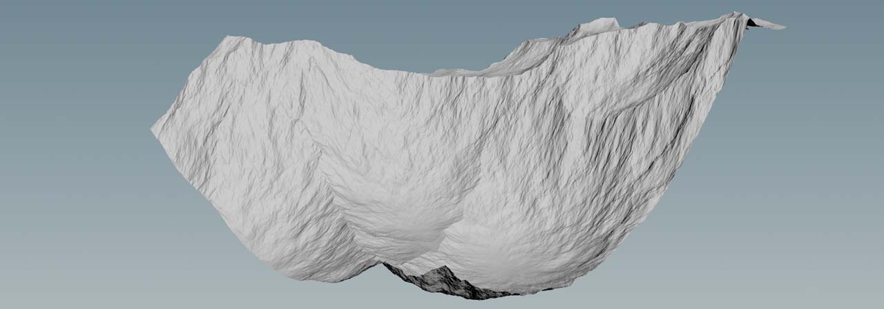
Set Amplitude to
1000to get very high mountains. -
To compensate for the extreme height, increase Element Size to
800. The parameter scales the noise and removes high-frequency spikes. -
Change Offset.X to
390and move the noise pattern along the positive X axis to see a different part of the noise pattern. -
On the Noise Settings section, set Noise Type to Worley Cellular F1.
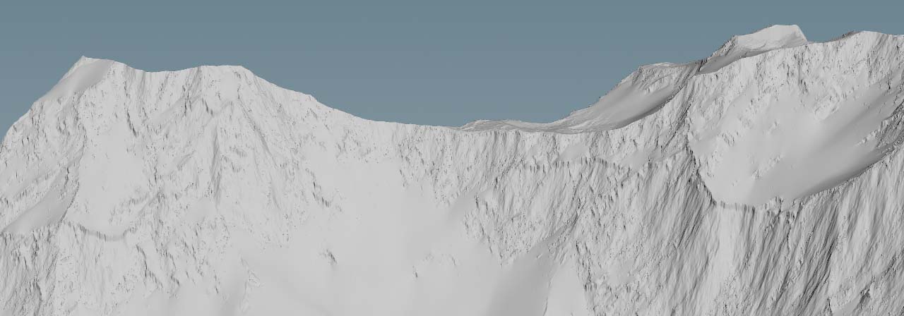
A ![]() HeightField Distort by Noise SOP breaks the edges and ridges, and creates the typical look of rough and weathered rock. Set the node’s Amplitude to
HeightField Distort by Noise SOP breaks the edges and ridges, and creates the typical look of rough and weathered rock. Set the node’s Amplitude to 15.
And here’s what you get with the above settings and values.
Slope mask 
With heightfields, things often look better when you apply masks to restrict an effect to certain areas of the terrain. Slump is no exception.
-
Lay down a
 HeightField Mask by Feature SOP and connect its input with the output of the upstream HeightField Distort SOP.
By default, the Slope method is turned on and you’ll be going to use this feature.
-
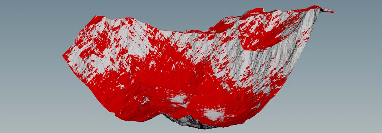
Change Min Slope Angle to
5and Max Slope Angle to50. The red areas indicate where the slump material will be added. -
The mask appears a bit aliased and to blur it, increase Smooth Radius to a value between
1.5and2.
Slump 
We want the sediment to fill the valleys and the space between the erosion channels in steeper areas of the terrain.
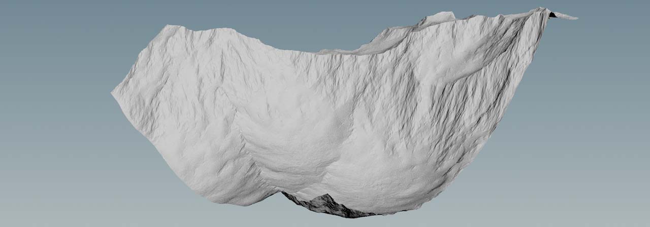
Add a HeightField Slump SOP and connect its input to the output of the mask node. When you connect the node and turn on its blue Display/Render flag, you’ll immediately see an effect. The masked areas are now smooth, because they contain all the fine sediment that came down from the mountainside.
-
On the Slump tab, change Slump Mode to Granular and you’ll get loose material filling parts of the terrain. The look, however, is pretty noisy and it seems as if rocks were sliding downhill.
-
To get rid of the noisy look, play with the Quantization parameter. The value basically defines the sediment’s granularity. For example, with a value of
0.1, the material becomes a smooth and amorphous mass without surface structures. Higher values like1, however, add more detail to the sediment. There’s often a kind of “threshold” where the structures start to look unnatural. So, please be cautious with very high values. -
You can also break the smooth area by setting a Repose Angle. This parameter describes the steepest angle at which a granular material can be piled on a horizontal surface without sliding. Try a value of
30.
Erosion 
To get the nice look with the erosion channels, turn on Do Erosion. Note that this mode is only available with the Granular mode.
When you turn on erosion, the heightfield disappears and the node shows an error, because it lacks two fundamental things from the Layer Bindings tab: Entrained Material (see Entrainment below) and Sediment. Without these layers, erosion won’t work. The layer for Entrained Material defines areas with already loose material and those areas won’t be considered during the slump-creation process.
Here, you’ll be using mask for both bindings. What you get now is a mountain range with lots of deep grooves that cover then entire terrain.
-
Go back to the Slump tab and change Global Erosion Rate to
0.6. This value depends on Spread Iteration and with every iteration, you’ll remove material. -
Erodability defines the rock’s softness. Higher values are good for the creation of rather soft types of rock like limestone or dolomite. If the rock consists of minerals like feldspar or quartz, e.g. in granite, it’ll become harder. Here, we're going to assume a rock of medium hardness and decrease the parameter’s value to
0.7.
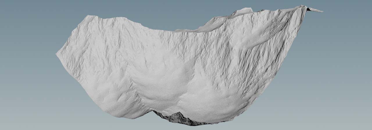
You can leave the remaining parameters, esp. those from the Advance Erosion tab, untouched. Many of them are only required for the creation of riverbeds. However, for the image below, Removal Rate is 0.5.
Now, the slump/debris fills the erosion channels and you get the typical look of highly eroded mountains with lots of slump that accumulated in deeper areas.
Tip
If you network already contains an upstream ![]() HeightField Erode SOP, you can use its
HeightField Erode SOP, you can use its debris and sediment layers as input layers for the slump node’s Entrained Material and Sediment.
Entrainment 
Entrainment sounds abstract, but fortunately it’s not difficult to understand.
Imagine a glacier, flowing down a mountain. On its way, the ice drags rocks and stones from the underlying bedrock and carries them downstream. In geology, this transportation process is called entrainment. When you measure the amount of rock that’s taken with the ice, you get the glacier’s entrainment rate. The same applies to gravel in rivers or material that’s washed out from steep slopes.
With Slump Mode set to Smooth, you can determine the Entrainment Rate. This controls the percentage of the entrained material that is dragged with the slumping material in each iteration. In other words: higher settings will make more material flow down with the slump material.
Flow Field tab 
On the HeightField Slump SOP you can find a Flow Field tab that lets you choose whether you want to Calculate Flow Fields or not. When you leave the option turned on, the node creates two layers. You can find the flow and flowdir output layers on the Layer Bindings tab.
The slump node’s flow fields are a basic form of the ![]() HeightField Flow Field SOP. On the flow field node’s help card you can find the following information about the
HeightField Flow Field SOP. On the flow field node’s help card you can find the following information about the flow and flowdir output layers.
-
The
flowlayers represent the cumulative material flow. This layer has two signed components (X and Y) representing the flow direction in voxel space. Because this is cumulative, if material flows left, then flows right, those two motions will cancel and the X component would be 0. -
The
flowdirlayer contains vectors for the XYZ directions, showing the average direction of flow at each voxel. This is converted from voxel space into geometry space. Note it does not include any change in height.