| On this page |
|
On the first look, the functionality of the  PointInstancer LOP appears to be similar to the
  Copy to Points LOP: you connect objects, create a point source, and get an appropriate number of instances. The main difference is that you can create and edit point instances at the same time.
Basic instancing 
The PointInstancer LOP’s main functionality is the creation of instances with scatter points. The first thing you need is a prototype. This is the object you’ll be instancing and you can use any geometry, for example a  Cube LOP, a
  Sphere LOP, or both as in this scenario.
On the Solaris stage, create the object nodes and chain them. Then, add a PointInstancer LOP and connect its second input with the output of the last geometry node. If you prefer the first input, choose it from the Prototype Source parameter’s dropdown menu.
When you double-click the instancer to dive inside its SOP network, you’ll find a USD Point Instancer Import SOP. For now, you can ignore this node as it’ll be described separately.
Points and attributes 
Points determine, where the instances appear. You can take points from different sources: objects, files, specialized nodes, particle systems, or VEX.
In many cases you’ll add attributes like pscale, N, or orient. With v (velocity) or w (radial velocity), you describe position changes over time and create motion blur. The  Scatter and Align SOP is a convenient way to create points and attributes. Note that all attributes from the SOP level will override what’s already defined on the node on the LOP level.
As long as you're inside a SOP network, you can check the attributes in the Geometry Spreadsheet pane. Back on the stage, the attributes are recognized by the point instancer and their values appear in the Scene Graph Details pane.
Example setup 
For the following considerations we need an example setup.
Inside the instancer, lay down a  Grid SOP and change its Rows and Columns to
 20 each. To create normals, add an  Attribute Create SOP. Connect its input with the output of the grid. For the Name parameter, enter
 N and set Size to 3 because its a vector. To align the normals with the Y axis, the second Value must be 1.
Scatter points 
This setup is going to use the grid points and the attributes are created with the Scatter and Align SOP.
-
Connect both inputs of the align node with the output of the Attrib Create SOP.
-
From the scatter node’s Mode dropdown menu, choose Add Attributes to Existing Point Cloud. This option will read the grid points from the second input.
-
Adjust the parameters of the Scale section and the Orientation tab. The actual values aren’t important because this scene is for demonstration purposes only. The parameters create
pscaleandorientattributes.
Instancer adjustments 
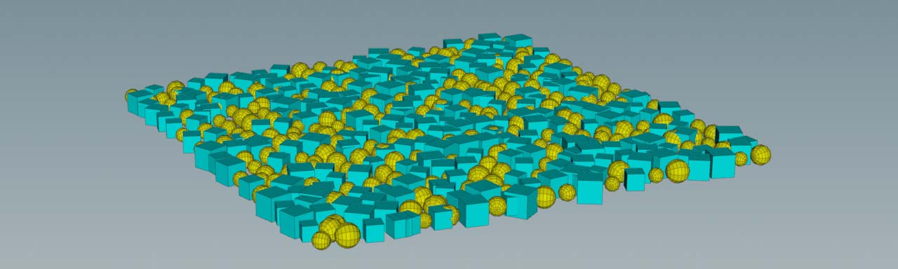
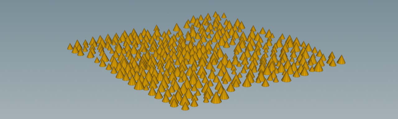
When you return to the stage and turn on the instancer’s blue Display flag, you’ll only get an empty viewport. This is because you have to specify the primitives you want to instance. Go to the instancer’s Source section. To include all primitives from the second input, replace the Primitives parameter’s default entry with /*. Your viewport should now look similar to this image - here with colors:
You can choose, which attributes you want to import from the SOP network. On the Import SOP Points section, there’s a list of Import toggles. For example, if you want to ignore the orient attribute, turn off Import Orientations. Please keep in mind that these toggles also play an important role when working with multiple instancers.
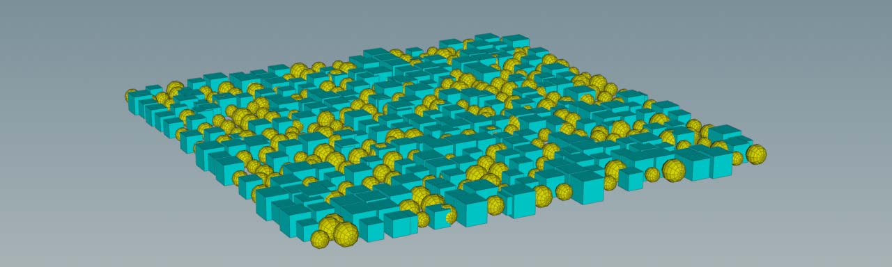
Another important parameter is Point Attributes to Copy. The parameter lets you define which attributes will be available downstream of the point instancer. With the default configuration you’ll lose all attributes tagged with ^.
The Prototype Assignment section controls how the prototypes are distributed. To shuffle the random distribution, expand New PointInstancers and change Seed. It’s also possible to use attributes if you want to add certain prototypes to specific points.
The Existing PointInstancers section is only relevant for editing points from another connected instancer.
Source primitives 
A common way is to import all prototypes with the /* wildcard on the Source ▸ Primitives parameter. Of course, you can also restrict this choice to a certain type or a group of primitives with primitive matching patterns. Let’s say you have sphere1, sphere2, sphere3, and cube1 prototypes. A few example matching patterns are:
-
/*brings in all four objects -
sphere*imports all spheres -
sphere[1,3]only considerssphere1andsphere3 -
/*1only showssphere1andcube1
You can also define a space-separated list of primitives like /cube /sphere. When you do that, please note that the order, given in the list, will be maintained. This is relevant for setups that already have point clouds with index values baked in that assume a different manually-specified order.
Destination 
This section defines where in the Scene Graph Tree the instancer will appear. You can change Root Prim to any valid path and integrate your prims into an existing scene. The default structure of the instancer’s tree is: @primpath/Prototypes/@protoprimname
-
@primpathis the name of the instancer node, for examplepointstancer1. -
Prototypesis the location where the prototype objects live. -
@protoprimnametakes the name of the prototype node, for examplesphere1
With Root Prim Kind you can also change the Prototypes branch’s Kind. The default (None) creates a group.
Point editing 
One of the strongest features is that you can edit and manipulate existing instancers with other point instancers. This method lets you branch off several instancers and edit particular groups while the source points remain untouched. You can also extract subgroups from already existing groups and create complex relationships. Let’s start with a basic transition.
Network setup 
For this example setup, you need a second point instancer.
On the stage, rename the already existing instancer to source. Then, add another PointInstancer LOP and connect its first input with the output of the source instancer. Change the name of the new node to edit. You can proceed with the default settings, but we recommend setting explicit paths to make sure that everything works as expected. Set the edit instancer’s:
-
Existing PointInstancers ▸ Primitives to
/source -
Prototypes ▸ Source ▸ Primitives to
/*
The USD PointInstancer Import SOP 
A note before we begin: By default, the instances are visible on the instancer’s SOP level and they might block the view on the points. To hide them, open the edit node’s Import SOP Points section and delete the entry from the Show LOP Stage in SOPs parameter. When you dive inside the editnode, you’ll only get the scatter points.
There’s also a USD PointInstancer Import SOP inside the instancer. The idea of this node is to import points from the existing source instancer, and manipulate them with the new edit instancer. The LOP Path and Primitive Path parameter should both point to the source node.
You can now start to work on the points, for example with a  Transform SOP. Connect the transform’s input with the output of the USD PointInstancer Import SOP and set Translate.X to
 -25. Back on the stage, you should see the translation in the viewport.
Attribute transfer 
You might have noticed that the overall look of the instances has changed after you've connected the edit node. This is because the original attribute values were re-applied. To fix this behavior, expand the Import SOP Points section and turn off the toggles of those attributes you don’t want to re-apply, for example Scales and Orientation.


When you import existing points, you might also notice that some attributes aren’t transferred, for example N. However, there might be situations where the editing process requires the original normals. On the source instancer’s Import SOP Points section, check the entry of the Point Attributes to Copy parameter: all attributes that are prefixed with a ^ character will be removed. To keep the normals, delete ^N from the list.
Edit Mode parameter 
The Existing PointInstancers section contains an Edit Mode dropdown menu with two options: Sparse and Overwrite. An example with the source and edit instancers will demonstrate how the modes work. You can proceed with the setup that has a Transform SOP inside. The points were translated 25 units along the negative X axis.
-
On the
editnode, set Existing PointInstancers ▸ Primitives to/source[0-100]. This pattern will only move the first 101 points. As long as Edit Mode is set to Sparse, the instancer won’t do anything that’s not explicitly specified on the node.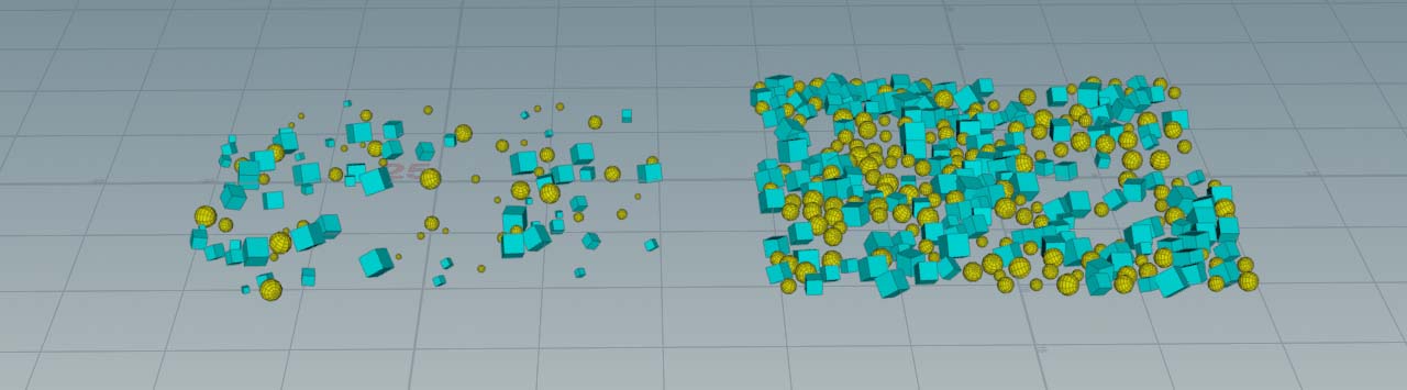
-
Now, choose Overwrite. The node will import only those 101 points you've defined in squared brackets.

Point groups 
The PointInstancer LOP also supports groups. Expand the Prototypes ▸ Source ▸ Import SOP Points section and look for Point Group. To create a group, dive inside an instancer and add one of Houdini’s SOP group nodes, for example Group SOP.
-
Select the points you want to group and apply a name, for example
transfer. -
From the Point Group dropdown menu, choose
transfer. Prototypes will only appear on thetransferpoints.
If you connect a second PointInstancer downstream, only the transfer points are transferred to the new instancer, but without the group’s name. Points that are not in this group are removed. However, it’s possible to inherit group names. For example if a point cloud already comes with groups, but you need those later in a second or third instancer. To keep the groups, Point Group must only be specified on the instancer where you actually want to use them.
Prototype Relationship Mode 
The PointInstancer is not only capable of manipulating points, but it’s also possible to append or replace prototypes. On the Existing PointInstancers section, you can find the Prototypes Relationship Mode dropdown menu with three options:
-
Preserve doesn’t change anything
-
Overwrite can replace the original prototypes with new prototypes from the
editinstancer’s second input -
Append adds new prototypes from the
editnode to the already existing prototypes of thesourcenode
Overwrite 
To replace the existing prototypes, create at least one new object and connect it to the edit instancer’s second input. If you prefer the first input, you can do that as well with Prototypes ▸ Prototype Source ▸ First Input.
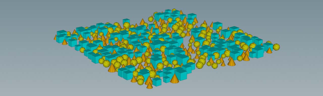
Now, the only thing you have to do is to expand the Existing PointInstancer section and set Prototypes Relationship Mode to Overwrite. You should instantly see the replaced prototypes.
Append 
Appending a new prototype works very similar to the Overwrite mode. You connect one or more new objects, and choose Append. Then, go to Prototype Assignment ▸ Existing PointInstancers and choose Random to include the new items. Of course, point attributes are also transferred to the appended prototypes.
Collapsing 
The examples created two instancer prims in the Scene Graph Tree: source and edit. This certainly helps to keep things clearly separated, but maybe you want to work with just one instancer prim throughout the entire pipeline?
In this case, turn off the Create Empty PointInstancer option on all instancer nodes except the first one that creates the original point source.
Prototype index 
In the previous chapters you've always worked with a random distribution of prototypes. By defining an integer index attribute on the scatter points, you can bring the prototypes into an order.
To make the attribute work, select the PointInstancer LOP and expand the Prototype Assignment ▸ New PointInstancers section. From the Prototype Index dropdown menu, choose Integer Attribute. The default name for the attribute is protoindex.
Now you add the protoindex attribute to the points inside the instancer. You can use any available method, for example a VEX script, groups, or the  Attribute Randomize SOP. Don’t forget that indices always begin with 0.
To assign prototypes to protoindex numbers, you must define their order on the instancer’s Source ▸ Primitives parameter. There you add a space-separated list like /cone /cube /sphere. In this case, the cone will be assigned to index 0, the cube will be on 1, and the sphere will live on points with an index of 2.

Multiple instancers 
The Existing PointInstancers ▸ Primitives supports a space-separated list of source instancers.
Nested instancers 
You can also create nested instancers. A typical example is a Christmas tree with light instances scattered on its branches. Then you take this tree as a new prototype and scatter it over a plane to build a complete forest. The setup is very similar to what you've created with the source and edit instancers.
Add at least one prototype, lay down a PointInstancer LOP and connect its second input with the output of the prototype. Rename the instancer node to source, dive inside, and create a point source. Here you can see a possible result.

Now you need another instancer with new scatter points.
-
Add the second instancer, connect its second input with the output of the
sourcenode, and rename it tonested. -
For Existing PointInstancers ▸ Primitives, enter
/source. -
For Prototypes ▸ Source ▸ Primitives, enter
/*. -
Dive inside the
nestednode and create a new point source, for example another grid. -
Use an
Attribute Create SOP to establish a pscalefloat attribute with a value of0.1. You can also apply colors to separate the instanced instances visually. -
Turn on the blue Display/Render flag of the last node of the network with the new points.
When you return to the stage, you should see the nested instances.