Found 68 posts.
Search results Show results as topic list.
Houdini Lounge » Turn Edges into Curve
-
- fabriciochamon

- 68 posts
- Online

Another option is to put desired eges in a gorup > polypath > blast (pick group and check “Delete Non Selected”). For some reason the Gamedev edge group to curve node crashed on me.
Technical Discussion » FLIP boundary layer - questions
-
- fabriciochamon
- 68 posts
- Online
Hi I'm trying to recreate the beach tank setup from scratch, and while I've went through the H16 FLIP masterclass and closely inspected all the nodes created by ocean shelf tools, I'm still having problems trying to mantain volume and transfer boundary velocities.
the “emission” part looks ok, I have an ocean spectrum->ocean source, which outputs particles + surface/vel volumes. easy
Now inside the simulation (dopnetwork), it seems that one would have 3 ways to define boundary layer settings:
1) inside flipsolver -> tab volume motion -> tab volume limits: “use boundary layer” toggle, which then asks for surface and velocity volumes (“fill new volume” is checked on my setup, and I'm not using waterline)
2) inside flipsolver -> tab volume motion -> tab solver: “guiding fields” group
3) drop two “source volume” nodes, make use of “sink FLIP” and “source ocean layer” presets, merge them and connect to the sourcing port of flipsolver
questions:
a) methods 1 and 3 look very similar, and while Ryan's H16 FLIP Masterclass uses 1, the default beachtank shelf tool uses 3. Why and when to choose one or another? What is the difference?
b) does method 2 also tries to achieve something similar ? or am I confused by the names here ?
c) if using method 1, is it correct to state that I need to use the output of oceansource node (“mantain” port) on both surface/vel volumes ? does the solver uses internal naming conventions to pick the correct data from the volume fields?
d) do I always have to toggle “reseed particles” (inside reseeding tab) for the boundary layer to work? or does it ignores this parameter and always seeds particles whenever is needed?
e) finally, there are some extra stuff inside the “ocean source” node when created from the shelf tools X the one created from tab menu. “sink” tab for example. Shouldn't they match ? what else am I missing when not using shelf tools ?
Sorry for that many questions, I rarely use shelves and I like to have full control over my trees.
thanks
Technical Discussion » Pyro flare up control
-
- fabriciochamon
- 68 posts
- Online
This is probably related to fuel accumulation. Your Source Volume node inside dopnet is set to “add”, so the fuel amount will always be higher when the emitter is static. You'd need to set source volume = copy, then work your way up to the desired density (as it will now accumulate less fuel, remaining at constant values). to do this just raise the scale source volume param to something like 8 or so.
be aware that for fast moving sources you also need to have more sim substeps, so the fuel emission also remais constant (i.e. without gaps).
be aware that for fast moving sources you also need to have more sim substeps, so the fuel emission also remais constant (i.e. without gaps).
Technical Discussion » Rigid Body Solver Settings - Chain Simulation
-
- fabriciochamon
- 68 posts
- Online
…just a side note, the one big reason why my previous settings (bullet solver with “concave” rbds) were not working was mainly due to my objetcts not having normals calculated. This plays a big role in handling penetrations, and once I add normals to my geometry everything was solid and I got a stable result with 20 substeps and 180 constraint iterations (“use parallel constraint solver”=checked).
Technical Discussion » Rigid Body Solver Settings - Chain Simulation
-
- fabriciochamon
- 68 posts
- Online
Hey thanks a ton for the hip Nima! and sorry for the delay..
this is great, and works nice and robust enough so that my pieces don't break. Now my only problem is with deforming bodies.. My chains are not procedural, but instead were modeled and animated by hand. So what I have to work is an alembic with deforming meshes. I know deforming geometry is not optimal for rbd simulations as I believe it is internally seen as if the objects teleport from one frame to another.. what is the proper way to handle collisions effectively in this case?
this is great, and works nice and robust enough so that my pieces don't break. Now my only problem is with deforming bodies.. My chains are not procedural, but instead were modeled and animated by hand. So what I have to work is an alembic with deforming meshes. I know deforming geometry is not optimal for rbd simulations as I believe it is internally seen as if the objects teleport from one frame to another.. what is the proper way to handle collisions effectively in this case?
Technical Discussion » Rigid Body Solver Settings - Chain Simulation
-
- fabriciochamon
- 68 posts
- Online
Hello everyone,
kind of starting in Houdini, sorry if this sounds like a noob question.
ok, so I have this simple rigid body sim where some chains are connected to a gem stone, the upper part (red circles) are an alembic animation (static/deforming rbd), the animation in this case is not too fast. The rest (other colored parts) are all active rbds.
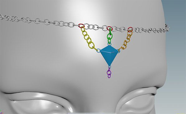
I'm not being able to get a solid result, even with higher substeps, pieces always go through each other breaking the chain. At first I tried the bullet solver (with packed geometry), too unstable..breaks easily..parts explode. (yes I'm using concave geometry)
After trying many settings I decided to changed to Houdini rbd solver which is of course a bit slower (I believe it does not support packed geometry,right?), but is far better and more stable.. still, haven't found a 100% reliable situation, because the chains also break at some point.
For the static rbds I'm using “deform geometry” and “re-evaluate SOPs to interpolate geometry”. Scene scale is set to cm, and the object sizes are pretty much real world. All collision volumes are checked and are small enough to retain details, so I believe I'm having trouble setting optimal engine parameters.
These settings below are kind of working, but too overkill. It needs to run overnight, but I'm sure I would not need this much steps to a relatively simple simulation, right ?
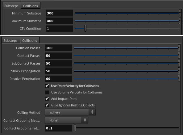
So my real question is, how do you tweak substeps and collision passes when simulating chains?
Thanks a lot!
kind of starting in Houdini, sorry if this sounds like a noob question.
ok, so I have this simple rigid body sim where some chains are connected to a gem stone, the upper part (red circles) are an alembic animation (static/deforming rbd), the animation in this case is not too fast. The rest (other colored parts) are all active rbds.
I'm not being able to get a solid result, even with higher substeps, pieces always go through each other breaking the chain. At first I tried the bullet solver (with packed geometry), too unstable..breaks easily..parts explode. (yes I'm using concave geometry)
After trying many settings I decided to changed to Houdini rbd solver which is of course a bit slower (I believe it does not support packed geometry,right?), but is far better and more stable.. still, haven't found a 100% reliable situation, because the chains also break at some point.
For the static rbds I'm using “deform geometry” and “re-evaluate SOPs to interpolate geometry”. Scene scale is set to cm, and the object sizes are pretty much real world. All collision volumes are checked and are small enough to retain details, so I believe I'm having trouble setting optimal engine parameters.
These settings below are kind of working, but too overkill. It needs to run overnight, but I'm sure I would not need this much steps to a relatively simple simulation, right ?
So my real question is, how do you tweak substeps and collision passes when simulating chains?
Thanks a lot!
SI Users » Constraint Network
-
- fabriciochamon
- 68 posts
- Online
not yet… still working on this one. will try to post a scene file whenever I find an answer.
SI Users » Constraint Network
-
- fabriciochamon
- 68 posts
- Online
Hi,
learning Houdini, so bare with me please…
I'm trying to glue pieces of a fractured box onto a stactic rbd. I have already filtered the primitives I want to stick, based on a bounding box. (see picture attached)
Is it possible to create the constraint relationships (each piece <-> stactic rbd) without having to write vex code ? Reading the help I can see that the constraint is defined inside a a geometry object, represented by a line, and each point must have a “name” attribute that is a pointer to the object it is constrained to.
I tested “glue adjacent” from shelf just to see how to constraint is built, but wanted to learn the nodal way before digging into vex.
example files would be greatly appreciated!
thanks!
-
- Quick Links