| On this page |
The ![]() APEX Autorig Component SOP provides different ways to create your own custom tools, including the use of rig component scripts, a built-in code interface that accepts APEX Script snippets, and the ability to merge rig functionality from a graph into an existing rig.
APEX Autorig Component SOP provides different ways to create your own custom tools, including the use of rig component scripts, a built-in code interface that accepts APEX Script snippets, and the ability to merge rig functionality from a graph into an existing rig.
Create custom functionality using APEX Script 
The APEX Autorig Component SOP provides an interface for writing APEX Script code. On the APEX Autorig Component SOP, set Component Source to Snippet. You can enter APEX Script code into the Snippet parameter and save the script functionality as its own rig component.
Merge graph functionality into an existing rig 
The fuse graph operation in the APEX Autorig Component SOP allows you to merge a graph (called a fuse graph) into an existing rig. In this way, you can start with a character rig, extract the part of the rig you want to update, edit the functionality in the APEX network view, and merge the updates back into the rig. This method provides a modular workflow for making changes to your rig.
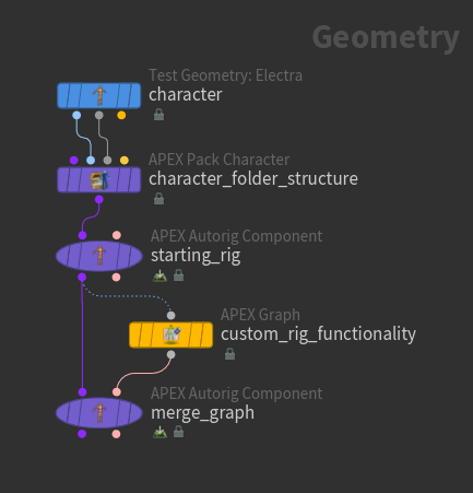
The fuse graph operation adds and connects the new nodes introduced in the ![]() APEX Graph SOP. It doesn’t rewire or remove nodes.
APEX Graph SOP. It doesn’t rewire or remove nodes.
Note
It is not recommended to put new nodes into a subnet in your fuse graph (the APEX Graph SOP). If you rename the subnet later on, your graph will no longer work. The fuse graph operation also cannot take existing nodes from a fuse graph and add it into a new subnet. It can, however, insert an entirely new subnet into an existing rig.
On this page, we demonstrate the following uses of the fuse graph operation:
-
Adding a control shape to a rig.
-
Adding custom IK functionality to a rig.
Add a control shape 
In this example, we add a control shape to a character’s spine joint:
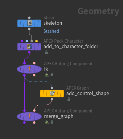
-
We start with a character’s skeleton and add it to a character folder structure using the
 APEX Pack Character SOP.
 -
Create an FK rig graph - on the
 APEX Autorig Component SOP,
 fk, set Component Source to FK Transform. See rigging a simple geometry and rigging a character for more information about the FK transform component.The FK rig graph can be seen in the APEX network view. The green nodes are the
 TransformObject nodes that represent the skeleton joints:
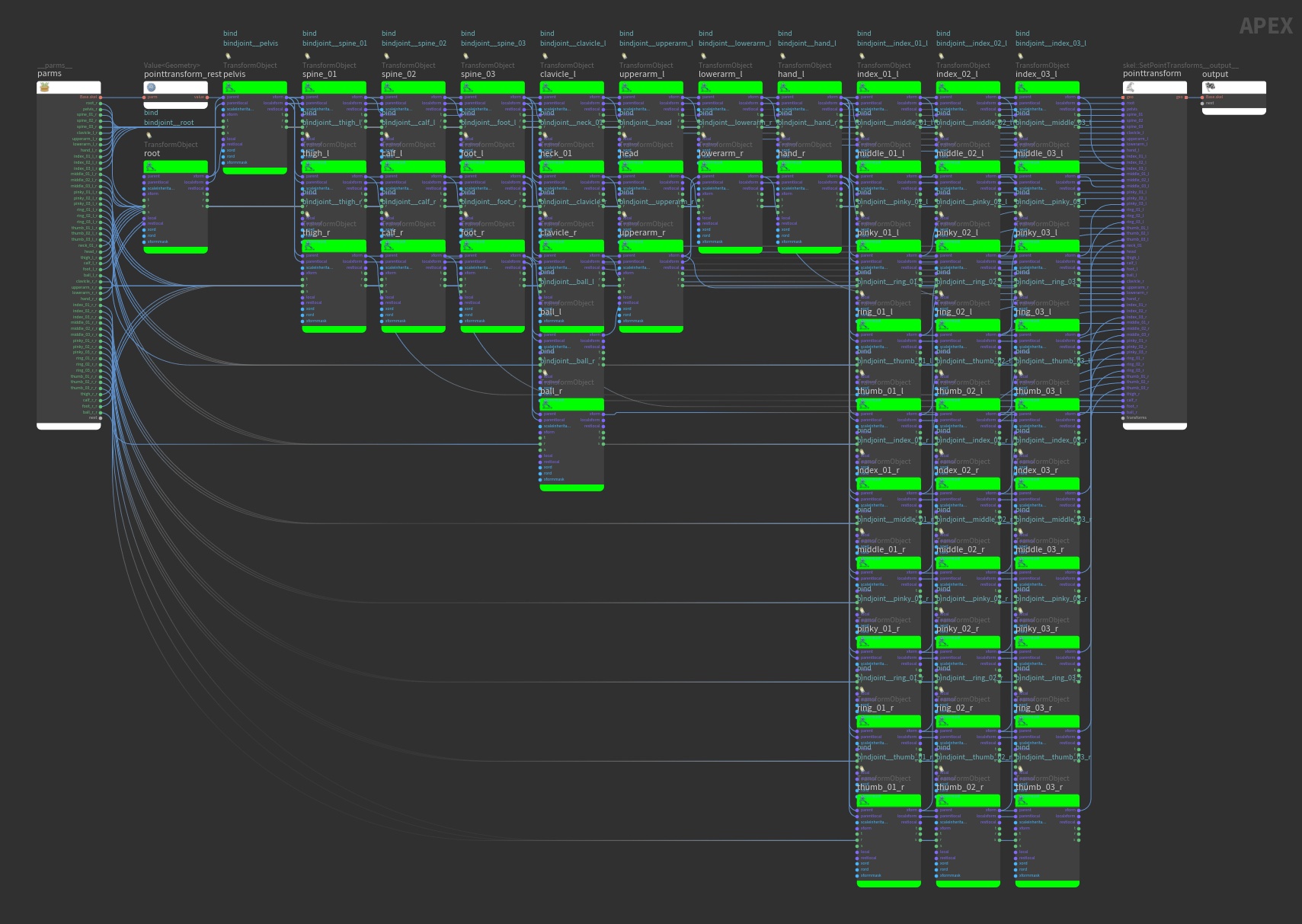
FK rig graph -
Build the fuse graph in the
 APEX Graph SOP. The APEX Graph SOP can take in a character folder structure and automatically find the rig graph in the folder structure. You can also tell the APEX Graph SOP to find a specific rig in the character folder structure by setting the Graph Path parameter. Once the APEX Graph SOP has a starting graph, you can edit the graph manually in the APEX network view.
 In this example, the APEX Graph SOP contains a copy of the entire FK rig graph as a starting point. From here, you have the option of simplifying the graph to make it easier to work with in the APEX network view.
-
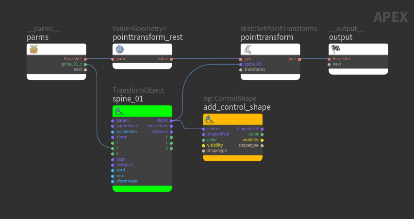
Select the APEX Graph SOP and go to the APEX network view to manually update the graph. Add a control shape to the spine joint by connecting a new
rig::ControlShape node to one of the spine’s TransformObject nodes: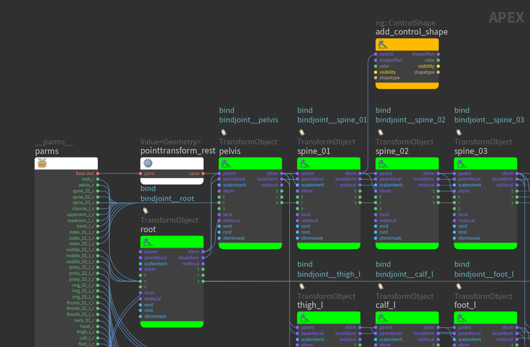
Add a spine control shape -
Select the rig::ControlShape node and press P over the APEX network view to open the node parameter window. Set color to
(1,0,0)and shapetype tobox_wires. -
In the animate state, you can see a visual representation of the rig in the viewport as you update the graph in the APEX network view. To enter the animate state, select the APEX Graph SOP, turn on its display flag, and click
 Animate on the left toolbar:
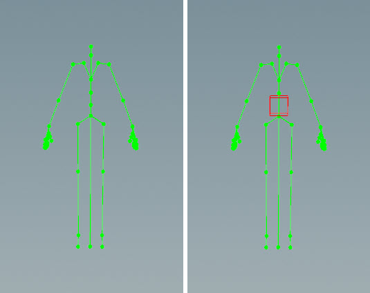
Original rig (left), added spine control shape (right) -
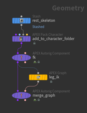
Merge the graph from the APEX Graph SOP into the original FK rig graph - on the second APEX Autorig Component SOP,
merge_graph, set Component Source to Fuse Graph. The fuse graph operation finds the new node and connects it into the original graph.See the merged graph in the APEX network view. On the APEX Autorig Component SOP,
merge_graph, the rig::ControlShape node is added to the FK rig graph from the first APEX Autorig Component SOP,fk. The new node is in green: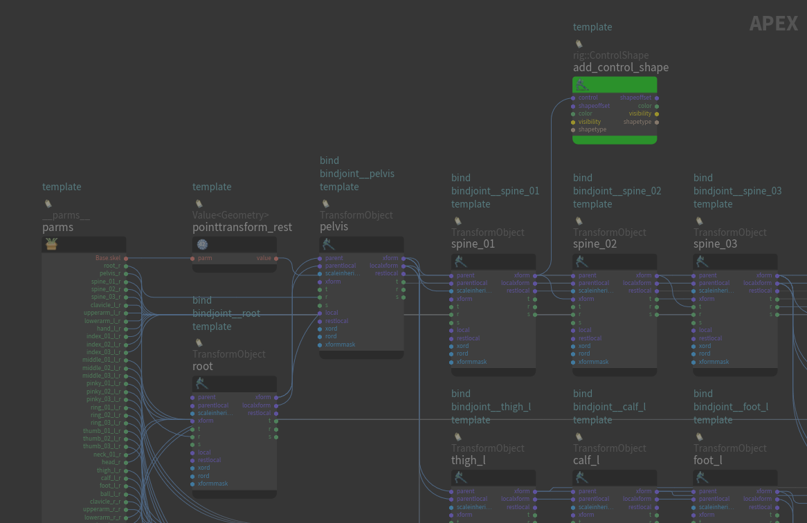
Updated FK rig graph with the new node
Simplify the graph 
If your change only affects certain parts of the rig, you can simplify the fuse graph by removing the TransformObject nodes that aren’t relevant to your change:
-
As a starting point, the fuse graph (in the APEX Graph SOP) contains the FK rig graph from the previous example. Remove all the TransformObject nodes except the
spine_01node: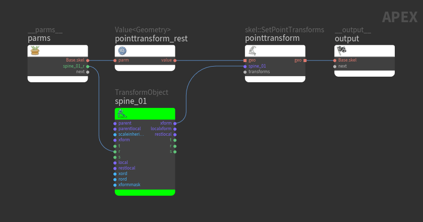
See graphs for deforming geometry for more information about the
 skel::SetPointTransforms node.
 -
We had removed
spine_01's parent in the process, so we need to place the joint back at its proper position on the skeleton:-
On the APEX Graph SOP, in the Rigging Scripts section, click Update Rest Transforms From Skeleton.
-
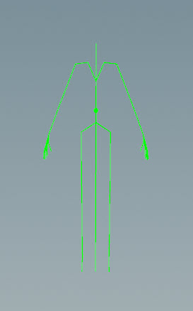
Enter the animate state on the APEX Graph SOP to see the TransformObject node on the spine joint:
-
-
Add a control shape to the spine joint by connecting a new rig::ControlShape node to the spine’s TransformObject node.
-
Select the rig::ControlShape node.
-
In the node parameter window, set color to
(1,0,0)and shapetype tobox_wires.
The added control shape can be seen in the animate state:
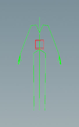
-
-
The fuse graph operation in the APEX Autorig Component SOP,
merge_graph, finds the new node, rig::ControlShape, and connects it into the original FK rig graph at thespine_01TransformObject node.
Add custom IK functionality 
The fuse graph operation allows you to create flexible tools that can be applied to different parts of a character’s rig. In this example, we manually construct a fuse graph that adds IK functionality to a character’s leg. We then mirror and transfer the IK functionality to the character’s arms:
-
In the APEX Graph SOP, we manually build a fuse graph that contains IK functionality for the character’s leg.
Note
The TransformObject node names in the fuse graph should match the joint names of the input skeleton.
Select the APEX Graph SOP, turn on its display flag, and enter the animate state:
-
On the APEX Autorig Component SOP,
merge_graph, set Component Source to Fuse Graph. The fuse graph operation adds the new IK functionality to the original FK rig graph. -
Select the APEX Autorig Component SOP,
merge_graph, turn on its display flag, and enter the animate state. -
Set the IK functionality to be mirrored on both sides of the rig. On our rig, the joints are named
<joint>_land<joint>_r, so change the From and To parameters to*_land*_r. The Mirror parameter is already turned on, so mirroring is performed by default once the correct joint name mappings are set: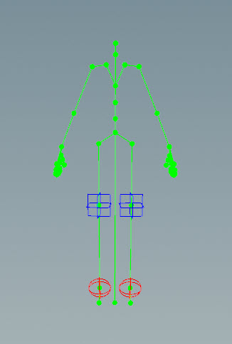
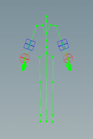
IK functionality mirrored on both legs -
We can now transfer the IK functionality to other joint chains like the arms. Click
 beside Mapping and add three mappings, one for each of the root, mid, and tip joints in the IK chain. Mappings are performed between TransformObject nodes, which represent the skeleton joints.
 -
For each joint to map:
-
Click the
 icon beside the From parameter. This is the joint that has the existing functionality.
 -
Select the joint in the viewport and press Enter. This populates the From parameter with the joint name.
Note
Select the joint, not the control that’s on the joint.
-
Click the
icon beside the To parameter. This is the joint you want to put the functionality on. -
Select the joint in the viewport and press Enter. This populates the To parameter with the joint name.
In our example, the three mappings are:
-
From =
thigh_l, To =upperarm_l -
From =
calf_l, To =lowerarm_l -
From =
foot_l, To =hand_l
-
-
The IK functionality is placed on the arms:
Save and reuse rig functionality 
You can save your custom rig functionality as its own rig component, then reuse it like you would any of the pre-built components:
-
On the APEX Autorig Component SOP, go to the Save tab. The Save tab is available when Component Source is set to Use Second Input, Snippet, or Fuse Graph.
-
Specify a name for the component in the Component Name parameter. For example, if you set the namespace field to
test, the name field tohello, and version to2.0, your component will be namedtest::hello::2.0. -
You can also specify a label (Component Label) for your component as well as a .png file (Component Icon) to use as an icon for the component in the Autorig Builder’s component catalog HUD.
-
In the Component Output File, set the path to save the component to. Save the file under
$HOUDINI_PATH/apexcomponent/<component_name>.bgeo. -
Click Save to Disk.
-
Click the
 icon beside the Component Source parameter to update your library of components. Your new component will appear in the Component Source drop-down, and you can use it like any other component.
 -
Once you select your new component from the Component Source drop-down, you can edit its source as an APEX Script snippet. Click
 beside Component Source, which decompiles the component into the Snippet parameter where you can make additional changes to the component.
 Note
For components created using the Fuse Graph operation, go to the Settings ▸ Header section, and set Template to Fuse Graph.
Preparing components for the Autorig Builder 
On the APEX Autorig Component SOP, you can make a custom component available as an interactive tool for the Autorig Builder using the parameters in the Rig Builder tab. The Rig Builder tab is available when Use with Rig Builder is turned on in the Save tab.
To prepare a custom component for use in the Autorig Builder:
-
If applicable, define a “segments” parameter that specifies where to apply the component. The Autorig Builder picks up on the “segments” keyword and allows the user to apply the component to different parts of the character in the drag-and-drop interaction. In APEX Script, you could define the “segments” parameter with something like:
segments: String = BindInput('', preset='tags')If you create the component using an APEX graph, you would have “segments” as an input parameter.
-
In the Rig Builder tab, specify the component’s input parameters that you want to appear in the Autorig Builder’s
gear menu:-
Click Generate from Component Parms to automatically populate the Config Control Parms multiparm with the component’s parameters that are in the parameter interface. For APEX Script, define the input parameters with
BindInput(), then click the button to have the parameters appear in the parameter editor. See creating graph interfaces for more information.or
-
Manually add the parameters to the Config Control Parms multiparm.
For the component parameters that are not specified in Config Control Parms, the Autorig Builder uses the default values that are set on the parameter (for example, when defining the parameter using
BindInput()). -
-
Set Drag Drop Interaction to Skeleton.
-
Set the Skeleton Source.
-
In the Joint Group parameter, select the joints in the Skeleton Source that are relevent to the component. For example, if you build a component that adds functonality to the arm, only the arm joints of the left side of the character should be included in this parameter. These joints are used as a reference skeleton when performing the drag-and-drop interaction in the Autorig Builder.
-
Set the Remove Side Indicator. This pattern is removed from the joint names so that the component can be used on both sides of the character.
-
On the
 APEX Autorig Builder SOP, click the
  icon to update your library of rig components. Your new component will appear in the component catalog HUD, and you can drag and drop it onto your guide character like any other component.
Component created using fuse graph 
In this example, we prepare the previous IK leg functionality for use in the Autorig Builder:
-
On the APEX Autorig Component SOP, Save tab, turn on Use with Rig Builder.
-
Set Drag Drop Interaction to Skeleton.
-
Set Skeleton Source to From Guide Skeleton. This uses the skeleton specified in Guide Skeleton.
-
In the Joint Group parameter, select the joints that the component applies to. These joints provide default positions for the fuse graph’s
TransformObject nodes. The TransformObject node names in the fuse graph should match the joint names of the input skeleton: -
Click the
 button beside Joint Group.
 -
In the rig tree view, select the joints, in our case,
thigh_l,calf_l, andfoot_l. -
Click Accept.
The Joint Group parameter is populated with the selected joints.
-
-
Set Remove Side Indicator to
*_l. This removes*_lfrom the joint names so that the component can be used on both sides of the character. -
On the
APEX Autorig Builder SOP, click the icon to update your library of rig components. Your new component will appear in the component catalog HUD, and you can drag and drop it onto your guide character.