| On this page |
|
The ![]() APEX Autorig Builder SOP allows you to interactively apply and configure pre-built and custom rig components for a character through the viewport. This makes the character setup process more intuitive and provides a way to quickly build up a complete rig for a character.
APEX Autorig Builder SOP allows you to interactively apply and configure pre-built and custom rig components for a character through the viewport. This makes the character setup process more intuitive and provides a way to quickly build up a complete rig for a character.
The APEX Autorig Builder SOP and ![]() APEX Autorig Component SOP can both be used to add rig functionality to a character, with the following differences:
APEX Autorig Component SOP can both be used to add rig functionality to a character, with the following differences:
APEX Autorig Builder SOP
-
Can add multiple rig components to a rig.
-
Can add rig functionality interactively in the viewport.
-
A limited set of rig component parameters can be modified interactively in the viewport.
APEX Autorig Component SOP
-
Can add one rig component to a rig.
-
Can be used to create custom rig components.
-
The full set of rig component parameters can be modified in the parameter editor.
See rigging a simple geometry and rigging a character for example uses of the APEX Autorig Component SOP.
Requirements and best practices 
The following are the requirements and best practices for using the Autorig Builder:
-
The character must face in the +Z direction.
-
The primary and secondary axes of the input skeleton must match the Main Axis and Secondary Axis parameters in the APEX Autorig Builder SOP.
-
Use unique joint names for the input skeleton.
-
The left and right body side indicators must be consistent in the input skeleton. For example, the joints on the left side can all be named
L_*or*_l, but don’t mix them. On the APEX Autorig Builder SOP, the Left and Right parameters in the Mirror section must match the left and right body side indicators on the input skeleton. For example, if your input skeleton’s joints are named*_land*_r, set these values in the Left and Right parameters. -
Use a scale value of 1 for all the transforms on the input skeleton. Scaled rest positions are generally problematic in rigging and animation.
Build a rig 
In this example, we start with a character’s shape and skeleton as inputs to the APEX Autorig Builder SOP. We then use the Autorig Builder to construct a rig with the following functionality:
-
Root control
-
Spine
-
Arms and legs
-
Hands and feet
-
Neck and head
The APEX Autorig Builder SOP can also create a rig if you don’t have an existing skeleton or shape for your character. See building a rig without a skeleton for an example.
Setup 
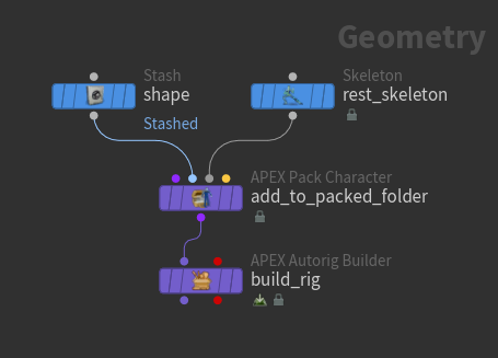
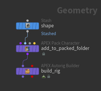
Input character elements like the shape and skeleton must first be packed into a character folder structure, which can then be piped into an APEX Autorig Builder SOP:
-
The
 APEX Pack Character SOP adds the input shape and rest skeleton to a packed character folder structure. The Shape Path and Skeleton Path parameters set the name of the shape and skeleton in the folder structure.
 -
Select the APEX Pack Character SOP and view the packed character folder structure in the rig tree view. In the rig tree view, set Type to Packed Folders:
/
-- Base.shp
-- Base.skel
-
The APEX Autorig Builder SOP builds a rig with an FK control hierarchy as a starting point. Enter the Autorig Builder viewer state - select the APEX Autorig Builder SOP, turn on its display flag, and click
 Animate on the left toolbar.
 -
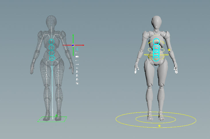
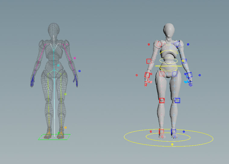
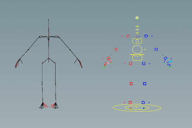
In the Autorig Builder viewer state, a guide for the character is shown on the left, and a test rig is shown on the right. The guide is where you configure your rig - the joint positions, skeleton, settings - everything that needs to be prepared for your final rig. The test rig is built based on your configurations. You add rig components to the guide, then preview and try out the functionality on the test rig:
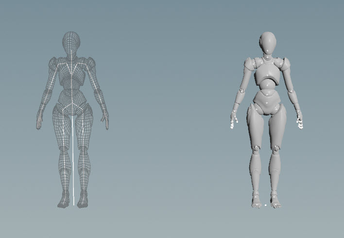
Guide (left), test rig (right) -
You can change the rest positions of the character’s joints by moving them around on the guide skeleton:
Root control 
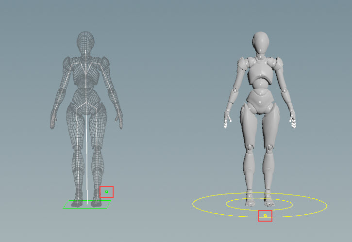
Add a root control to the character:
-
Drag the Root component from the component catalog HUD onto the guide, and click
 or press Enter over the viewport. In the parameter editor, an entry for the root control is added to the Segments multiparm in the Build tab. To see the root control on the test rig, press H over the viewport or click the
  Update Rig icon in the parameter editor:
Add a root control to the rig A few notes:
-
The order in which you add the rig components is important. If you want to parent all of the character’s controls to a root control, first add the root component, then add the other components. The entries in the Segments multiparm represent the order in which the components are built.
-
To add components to your rig, drag and drop from the component catalog HUD instead of using the Segments multiparm. The APEX Autorig Builder SOP is designed for the drag-and-drop viewport interaction. The Segments multiparm is moreso a place to store and view the rig component data.
-
In the parameter editor, you can turn on Auto Update to automatically update the test rig when changes are made to the guide. For faster performance, you may want to turn off Auto Update while dragging and dropping components onto your guide. After adding all your components, you can turn on Auto Update to see all the added controls at once.
-
-
After you move the test rig around, you can press N over the viewport or click the
 Reset Test Rig button in the parameter editor to reset the rig.
 -
To change the color of the root component on the guide, click the color chip for the root in the parameter editor, Build tab.
Configuring the root control 
You can configure the settings on the guide and test rig through the two ![]() gear menus:
gear menus:
-
On the guide, click the
 icon to open up a menu of settings for configuring the root control. You can reposition the menu by dragging on the icon.
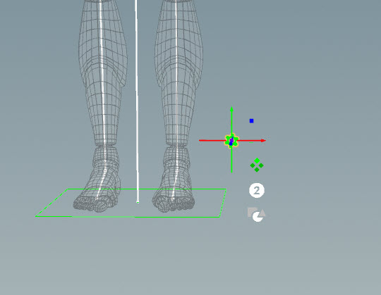
-
To change the number and shape of the root controls, click and drag on the appropriate icons in the menu:
-
The settings for the guide can also be updated in the parameters HUD - select the
icon, press G over the viewport to open the parameters HUD, and go to the Controls tab.Tip
Depending on your transform handle settings, there may be a plane that appears at the transform handle of the
icon that makes it difficult to select some of the settings directly below it:
To turn off the plane:
-
Press P over the viewport to bring up the handle preferences.
-
Click the Open Handle Preferences button.
-
In the Houdini Preferences window that opens up, go to the Preferences tab.
-
Turn off Allow Planar Dragging of Translate Handles Between Axes.
-
Click Accept.
-
-
There is also a
menu for the test rig. For the root control, the only available option is the visibility toggle:
Spine 
Add spine functionality to the rig by dragging the Spine component onto the guide. In the parameter editor, an entry for the spine is added to the Segments multiparm in the Build tab.
To see the spine joints and controls, click the spine’s ![]() icon on the guide:
icon on the guide:
To move the spine component to another part of the skeleton:
-
Click the spine’s
menu on the guide. -
Select the segments icon.
-
Click and drag the spine component to another joint.
-
Press Enter.
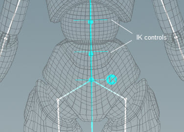
Posing the guide skeleton 
On the guide skeleton, there is an FK/IK icon that you can click to choose between posing in FK or IK. When you switch to IK posing, IK controls appear that you can select for posing:
Note
This functionality is different from the IK/FK setting in the test rig’s ![]() menu.
menu.
To reset the guide skeleton, click the ![]() icon in the parameter editor.
icon in the parameter editor.
Configuring the spine controls 
The ![]() menu on the guide provides several options for configuring the spine functionality. If you turn on the addstretchcontrol toggle, an option appears in the test rig’s
menu on the guide provides several options for configuring the spine functionality. If you turn on the addstretchcontrol toggle, an option appears in the test rig’s ![]() menu for controlling the stretch in the spine. See the gear menu options for the different types of interaction gadgets in the
menu for controlling the stretch in the spine. See the gear menu options for the different types of interaction gadgets in the ![]() menu.
menu.
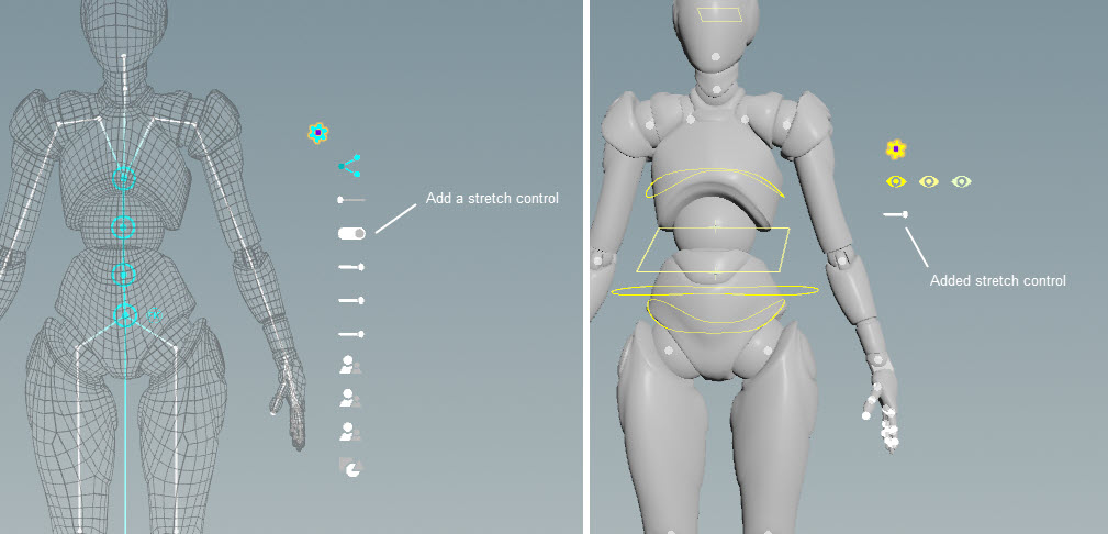
The stretch and squash slider options below the addstretchcontrol toggle allow you to control the amount of stretch and squash on the spine. These options are only applicable when addstretchcontrol is toggled on. See the spline rig component for descriptions of these options.
Arms and legs 
Add arm and leg functionality to the rig by dragging the Arm and Leg components onto the left side of the guide. To mirror rig functionality, components must be put onto the left side of the skeleton. If you drag a component onto the right side, its functionality will not be mirrored.
Note
The Arm component is a 3-joint setup that does not require the guide skeleton to have a clavicle joint. If it does find one, it will use it. The Arm Clavicle component, on the other hand, is a 4-joint setup that requires the guide to have a clavicle joint.
Settings on the guide 
Below are some of the settings in the guide’s ![]() menu:
menu:
Mirror icon
Turns on and off mirroring of the arm/leg functionality to the other side of the rig.
Turn on the useik toggle
Adds the IkStretch option to the test rig’s ![]() menu.
menu.
Turn on the ikfkblend toggle
Adds ikfkblend, ikfk_switch, and pinControls to the test rig’s ![]() menu. This setting is only applicable when useik is toggled on.
menu. This setting is only applicable when useik is toggled on.
See the multi IK rig component for descriptions of the other slider and toggle options.
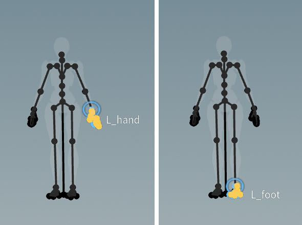
Reparenting controls 
You can use the parenting option in the guide’s ![]() menu to set a new parent for the pole vector and tip controls. Here, we reparent the leg’s pole vectors to the cog:
menu to set a new parent for the pole vector and tip controls. Here, we reparent the leg’s pole vectors to the cog:
-
On the guide’s
menu for the leg, select the parenting icon for the pole vector. -
Select the cog control.
-
Press Enter.
In the video on the left, the leg pole vector controls are not parented to the cog control, so the pole vectors don’t move with the cog. In the right video, we reparent the pole vector controls to the cog control, so the pole vectors move with the cog:
Settings on the test rig 
IK/FK blend 
You can perform IK/FK blending on the test rig using the ikfkblend and ikfk_switch options in the test rig’s ![]() menu (these options are available if ikfkblend is toggled on in the guide’s
menu (these options are available if ikfkblend is toggled on in the guide’s ![]() menu):
menu):
Pinning controls 
Click the pin icon in the test rig’s ![]() menu to add the component’s IK and FK channels to the channel list. When these channels are added to the channel list, you can set keyframes on all the relevant IK and FK controls without needing to first select the individual controls.
menu to add the component’s IK and FK channels to the channel list. When these channels are added to the channel list, you can set keyframes on all the relevant IK and FK controls without needing to first select the individual controls.
Hands and feet 
Add functionality for the hands and feet by dragging the Hand Simple and Foot components onto the guide:
If your input skeleton has fewer fingers than the Hand component, turning on Remove Un when dragging and dropping the hand component removes the unnecessary fingers so that extra finger controls aren’t created. You can also choose not to add certain fingers by using the ⌃ Ctrl hotkey:
-
Drag and drop the Hand component onto the guide.
-
Hold ⌃ Ctrl and select the joints you don’t want to add. The selected joints will turn red. When you release ⌃ Ctrl, the joints will turn black, indicating that they are no longer mapped to the skeleton, so controls will not be created for those joints.
-
Click
.Removing the extra finger when adding the component 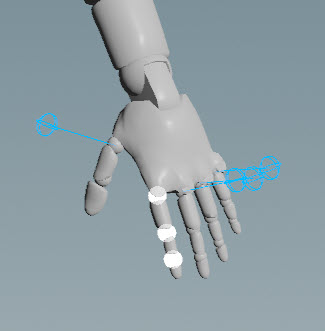
Index finger removed on the test rig
Settings on the hand component 
Below are some of the Hand component settings in the guide’s ![]() menu:
menu:
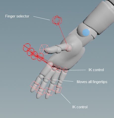
pianohands toggle
When pianohands is turned off, you have a simple hand functionality, with FK controls on each of the finger joints as well as a selector control for each finger. Piano hands provides a more complex hand functionality that includes additional IK controls at the base and tip of each finger as well as a control that moves all the fingertips at once. When pianohands is turned on, the ikfkblend, ikfk_switch, and pinControls options are available in the test rig’s ![]() menu. Set ikfk_switch to IK to see the controls that affect the fingertips.
menu. Set ikfk_switch to IK to see the controls that affect the fingertips.
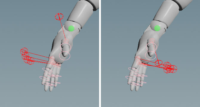
flipselectors toggle
Switches the position of the test rig’s finger selector control to the outside of the hand. The finger selector control selects all the corresponding finger’s joints to make it easier to pose the entire finger.
Neck and head 
Instead of using a rig component for the neck and head, we simply want to configure the existing FK controls (created initially by the Autorig Builder) to be rotate only. We can do this with the use of tags:
-
Select the neck and head joints on the guide.
-
Press ⇧ Shift + H over the viewport.
-
In the Add Tag pop up, enter a tag name for the neck/head group of joints. In our example, we use
neck_head.If you want the tag mirrored, name the tag with the body side indicator, for example,
L_testarm. -
Press Enter. A
menu is created near the joint selection on the guide, and an entry is added to the Build tab (in the parameter editor) with the entry’s drop-down menu set to Add Segment Tag. You can now use the guide’s menu to configure the color, shape, and size of the neck and head controls on the test rig. You can also choose whether to promote the translate, rotate, and scale of the controls. -
Only promote the rotate controls for the neck and head:
-
Turn on the
promote_rtoggle so that you can rotate the neck and head controls. -
Turn off the
promote_tandpromote_stoggles so that translate and scale for the neck and head controls aren’t available on the test rig. -
If you turn off
promote_t,promote_r, andpromote_s, the neck and head controls will not appear on the test rig.
-
-
Set the color, shape, and size of the neck and head controls.
Build a rig without a skeleton 
The APEX Autorig Builder SOP can build a rig even if you don’t have an existing skeleton or shape for your character:
-
In the network editor, put down an APEX Autorig Builder SOP with no connected inputs.
-
Enter the Autorig Builder viewer state - select the APEX Autorig Builder SOP, turn on its display flag, and click
Animate on the left toolbar. -
If you drag and drop from the component catalog HUD, and you don’t drag onto an existing joint, the Autorig Builder adds the new joints to your rig. In this way, the Autorig Builder can create a whole new skeleton for your character:
If you don’t drag onto an existing joint, the Autorig Builder will try to parent the component to the closest joint, shown by a green line. You can drag the green joint to change to a new parent. If you drag and drop the green joint away from the guide, this unparents the component. To reparent the component, hold ⇧ Shift, which activates parenting mode, and drag the green joint (now the root joint of the component) to the joint you want as the parent:
If you only have a shape input for your character, you can turn on Add Preview Skin Weight in the parameter editor Settings tab, which creates proxy weights and allows you to preview the rig functionality even if you don’t have capture weights on your character:
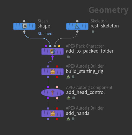
Chaining together rig component SOPs 
You can build up a rig in several steps by daisy-chaining APEX Autorig Builder and ![]() APEX Autorig Component SOPs:
APEX Autorig Component SOPs:
-
On the first APEX Autorig Builder SOP, build a rig with root, spine, arm, and leg components.
-
On the APEX Autorig Component SOP, add an APEX Script snippet that configures the head control.
-
On the second APEX Autorig Builder SOP, add rig functionality for the hands. In the parameter editor, turn off Skeleton To FK so the node doesn’t try to create an FK hierarchy since we already have a rig.
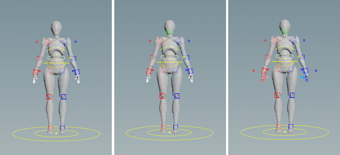
Starting rig (left), updated head control (middle), add hands (right)
Reusing rig configurations 
After you build a rig using the Autorig Builder, you can reuse the rig configuration by saving it as its own rig component, or piping the configuration directly into another APEX Autorig Builder SOP.
Saving rig configurations 
To save your rig configuration as its own component:
-
On the APEX Autorig Builder SOP, go to the Save tab in the parameter editor.
-
Specify a name for the component in the Component Name parameter. For example, if you set the namespace field to
test, the name field tohello, and version to2.0, your component will be namedtest::hello::2.0. -
Click Save to Disk. The component is stored in the location specified in the Component Output File parameter.
-
Click the
 icon to update your library of rig components. Your new component will appear in the component catalog HUD, and you can drag and drop it onto your guide character like any other component.
Using rig configurations as a template 
After you build a rig using the APEX Autorig Builder SOP, the second output of the SOP contains the list of operations for constructing the full rig (these operations can be seen in the parameter editor under the Build tab). This second output is essentially a script for building the rig, and can be input into another APEX Autorig Builder SOP, acting like a template for creating another character’s rig:
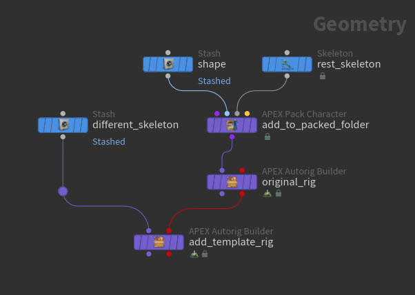
In the second APEX Autorig Builder SOP, you can drag and drop the entire rig from the first character onto another character by using the “Input” component in the component catalog HUD. The proportions, joint orientations, and joint names between the two skeletons can be completely different:
Gear menu options 
The icons in the ![]() menu indicate the type of interaction required to change the setting. Some of these settings are available on the guide, and some are available on the test rig.
menu indicate the type of interaction required to change the setting. Some of these settings are available on the guide, and some are available on the test rig.
Setting Icon |
Functionality |
|---|---|
|
Change the number of elements (guide joints) or controls - click and drag the number icon to open a menu of available values. |
|
Toggles mirroring of the controls on the other side of the rig. |
|
Change the joint segment that the rig component applies to:
Once you click the segment icon, you are in the segment state. You can exit the state by pressing ⎋ Esc. See building a rig without a skeleton for an example of how to unparent and reparent a component. |
|
Toggle - click and drag to the right to turn on, click and drag to the left to turn off. |
|
Slider - click and drag to increase or decrease the value. |
|
Specify the tag that the functionality applies to. For example, the twist functionality in the Leg component is applied to controls that have a tag named
Once you click the tag icon, you are in the tagging state. You can exit the state by pressing ⎋ Esc. |
|
Reparent the control:
Once you click the parenting icon, you are in the parenting state. You can exit the state by pressing ⎋ Esc. |
|
Change the color of the control - click and drag the color icon to open a menu of available colors. |
|
Change the control shape - click and drag the shape icon to open a menu of available shapes. |
|
Toggle the visibility of the primary, secondary, and tertiary controls on the test rig. |
|
Switch to IK or FK. This option is available on the test rig if the toggles for useik and ikfkblend are turned on in the guide’s |
|
Adds the rig component’s channels to the channel list. This allows you to set keyframes on all the relevant controls for the component as you pose the character. |


Component catalog 
The component catalog HUD displays the available rig components that you can drag and drop onto your character. You can filter for specific components using the ![]() search bar by supplying the component name or the tags on the component.
search bar by supplying the component name or the tags on the component.
To update the tags on the component:
-
 click the component and select Edit Metadata.
 -
In the Metadata Editor window that pops up, select the tags you want to add to the component.
-
Click OK.
To rename a component in the component catalog HUD, do one of the following:
-
Click the component name.
-
the component and select Rename.
-
the component, select Edit Metadata, update the Label field, and click OK.
How-to 
| To... | Do this |
|---|---|
|
Update the test rig |
In the Autorig Builder state, press H over the viewport. |
|
Reset the guide |
In the parameter editor, click the |
|
Reset the test rig |
In the Autorig Builder state, press N over the viewport. or In the parameter editor, click the |
|
Change the color of the rig components on the guide |
In the parameter editor, Build tab, click the color chip beside the segment. |
|
Change the color of the controls on the test rig |
In the parameter editor, Post Process tab, click the color chips to choose a different color for the left, middle, and right sides of the rig. To use the colors on the guide, turn off Use Color Template. |
|
Delete a rig component |
Select the rig component’s or In the parameter editor, Build tab, |
|
Update your library of rig components |
In the parameter editor, click the This also updates the icons for the rig components in the component catalog HUD. |
|
Reparent a component |
To reparent a component when dragging and dropping from the component catalog HUD:
|
|
Remove certain body parts from being added by the rig component |
For example, to remove certain fingers from being added by the Hand component:
See an example here. |
|
Add a control or FK chain to the character |
Drag the Add Control or FK Chain component from the component catalog HUD onto the guide, and click If you don’t drag onto an existing joint, the Autorig Builder will try to parent the control/chain to the closest joint, shown by a green line. You can drag the green joint to change to a new parent. If you drag and drop the green joint away from the guide, this unparents the component. To reparent the component, hold ⇧ Shift, which activates parenting mode, and drag the green joint to the joint you want as the parent. |
See an example here. |
|
|
Move a joint without moving its child joints |
Child compensate mode keeps a child joint at its current position even when its parent is being moved around. Turn on child compensate mode by pressing A over the viewport, then moving a joint. If you press A again, child compensate mode will be turned off: |
|
Show a smaller number of options in the guide’s |
The options that are hidden can be viewed in the parameters HUD, Controls tab when you select the guide’s |
|
Configure the joint display of the guide skeleton |
|
|
Reorient joints |
|
|
Tweak control shapes |
This operation is meant to be a post-processing step after you've fully configured your rig.
|
|
Ignore certain joints when dragging components onto the guide |
When dragging a rig component onto the guide, a mapping is performed between the component and the guide joints. To ignore certain joints in the rig comparison:
The defaults currently specified are usually helper joints you wouldn’t want to map. |