| On this page |
Overview 
On this page, we use several pre-built rig components to build a complete rig for the ![]() Electra test geometry. The pre-built components are available from the
Electra test geometry. The pre-built components are available from the ![]() APEX Autorig Component SOP, which provides an interface for adding rig functionality such as FK, IK, and bone deform.
APEX Autorig Component SOP, which provides an interface for adding rig functionality such as FK, IK, and bone deform.
In our example, we add the following rig functionality to construct the final rig for Electra:
-
FK rig hierarchy based on Electra’s skeleton joint hierarchy
-
Bone deform
-
Root and cog controls
-
Spine
-
IK arms and legs
-
Twist functionality on the arms
-
IK/FK blend
-
Reverse foot
-
Look at
-
Configure the look of Electra’s controls
The example in this file demonstrates how to use pre-built rig components to build up a rig for Electra.
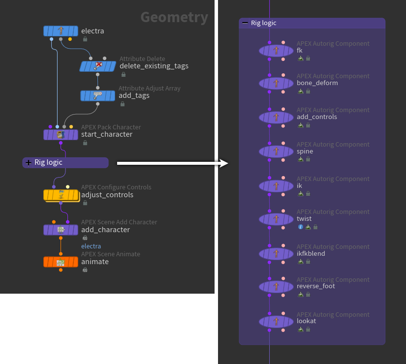
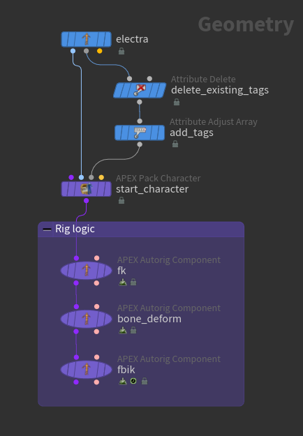
The following sections on this page provide step-by-step instructions for building up the final network shown below:
Setup 
Electra’s character elements (skin and skeleton) must be packed into a character folder structure before rig functionality can be added using APEX Autorig Component SOPs:
-
On the
 Electra SOP, set the Output parameter to Skin Surface. This outputs Electra’s shape as its 1st output, and Electra’s skeleton as its 2nd output.
 -
Remove the tags currently on Electra - on the
 Attribute Delete SOP, set Point Attributes to
 tags. In our example, we start with a fresh skeleton and add the tags we need as we build up Electra’s rig. -
In the network editor TAB menu, search for Attribute Adjust Tags, an alias to the
 Attribute Adjust Array SOP. We use Attribute Adjust Tags to add tags to Electra’s skeleton. These tags are then used downstream by various rig components to build up Electra’s rig. By default, Attribute Adjust Tags sets the Attribute Class parameter to Point, and Array Type to String.
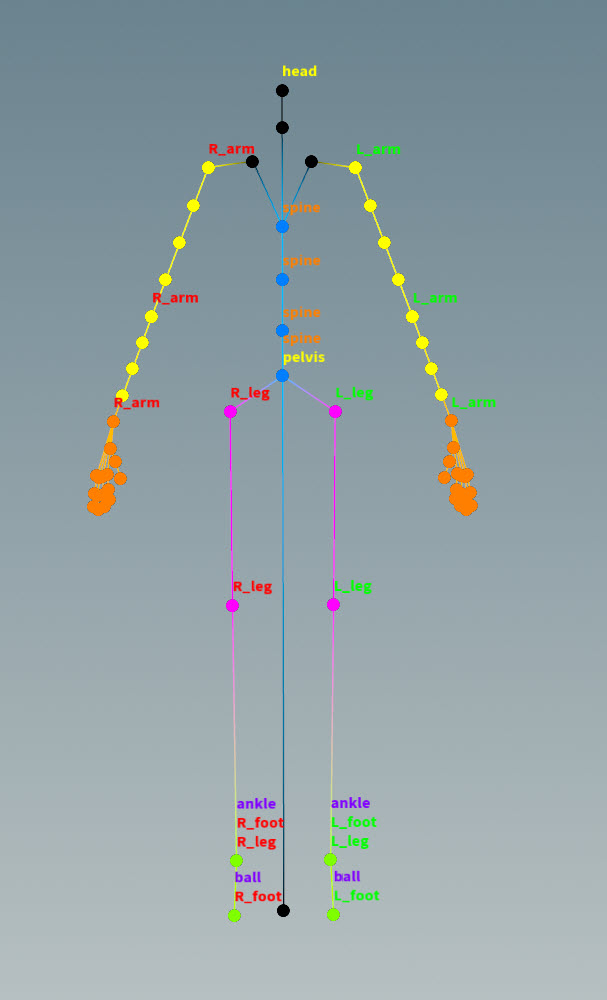
 The subsequent sections on this page describe when tags are added to the skeleton. The image below shows an example of some of the tags that will be added to Electra:
-
The
 APEX Pack Character SOP adds Electra’s shape and skeleton to a packed character folder structure. By default, Shape Path is set to
 /Base.shp, and Skeleton Path is set to/Base.skel. These are the names given to Electra’s shape and skeleton once they are packed into the folder structure. Select the APEX Pack Character SOP and view the character folder structure in the rig tree view. In the rig tree view, set Type to Packed Folders:/ -- Base.shp -- Base.skel
Note
If you turn on Add FK and Bone Deform Components, this automatically adds FK and bone deform functionality to the character’s rig, so you won’t need to manually add the FK transform and bone deform rig components described in the section below. When building the rest of the rig, you don’t need all the joints available as FK controls, so remove the entries in the Translate Group, Rotate Group, and Scale Group parameters.
FK and bone deform 
We now create an FK rig, then add bone deform logic to view the FK functionality on Electra:
-
The
APEX Autorig Component SOP, fk, is the FK transform rig component, which creates a rig graph by translating Electra’s skeleton into a rig hierarchy; it takes each of the skeleton joints and creates a TransformObject node in the rig graph. You can see the TransformObject nodes in the APEX network view.
-
On the
fknode, set the Component Source parameter to FK Transform. -
By default, the rig created by the FK transform component is named
Base.rig(specified in the Rig section, Name parameter). -
In the Source tab, the Guide Skeleton parameter specifies the skeleton to use to create the rig hierarchy.
-
The FK transform component adds the rig graph to the character folder structure. Select the
fknode and view the folder structure in the rig tree view:/ -- Base.rig -- Base.shp -- Base.skel
-
-
The APEX Autorig Component SOP,
bone_deform, is the bone deform rig component, which adds bone deformation logic to the rig graph. On thebone_deformnode, set Component Source to Bone Deform. The default values in the Rest Skeleton, Rest Geo, and Output Geo parameters match the names of the character elements in the character folder structure. -
Perform FK posing on Electra in the animate state:
-
Select the
bone_deformnode and turn on its display flag. -
Click
 Animate on the left toolbar or press Enter in the viewport:
Electra with FK behavior
-
-
Electra’s joints can be translated and rotated because the
promoteproperty is stored on Electra’s skeleton. To see the properties on the skeleton:-
Select the Electra SOP.
-
Open the geometry spreadsheet.
-
From the drop-down menu beside Electra’s name on the top toolbar, select Capture Pose.
-
Select
 on the top toolbar to display the information for each joint.
 -
 an entry under the properties column and select Inspect. The properties on the joint are listed, including
 "promote":"t r", which specifies that the joint’s translate and rotate components are promoted.
-
-
To build the rest of the rig, we don’t need all the joints available as FK controls, so we can remove the
propertiesattribute from Electra’s joints:-
On the Attribute Delete SOP, add
propertiesto the Point Attributes parameter. Point Attributes is now set to “tags properties”. -
On the
fknode, Controls tab, remove all the entries in the T Promote Group, R Promote Group, and S Promote Group parameters.
-
Add root and cog controls 
We now add root and cog controls to the Electra rig using the transform driver rig component. The root control sits at the skeleton’s root joint, and the cog control sits at the skeleton’s pelvis joint. The cog control is used later as the parent of the spine joint chain.
-
On the Attribute Adjust Array SOP, add a tag for the pelvis. The
pelvistag is picked up by the transform driver rig component. See preparing skeletons for more information on creating tags.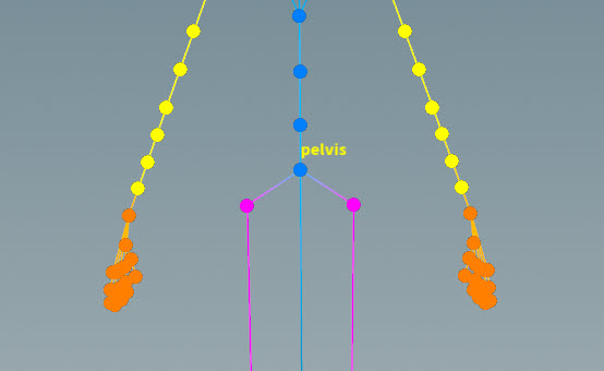
Pelvis tag -
The APEX Autorig Component SOP,
add_controls, adds the root and cog controls to Electra. On theadd_controlsnode, set the Component Source parameter to Transform Driver. -
Set the following for the root control:
-
In the Driven tab, set Driven Transforms to
C_root. This is the joint that is driven by the new control. -
In the Control tab, set Driver to the name of the new root control. In our example, we set Driver to
Main. -
Set Driver Guide to
C_root. This places the new control at the root joint. -
Change the control shape in the Shape tab. In the Shape parameter, you can specify any of the APEX control shapes listed here.
-
-
Click
 beside Setups to add another control.
 -
Set the following for the cog control:
-
In the Driven tab, set Driven Transforms to
C_pelvisbecause we want the cog control to drive theC_pelvisjoint. The Driven Transforms parameter also accepts APEX path patterns, so you can specify joints with the#tagsyntax, for example,#pelvis.Note
Joint names and tags are case-sensitive.
-
In the Control tab, we set Driver to
Cog. This is the name of the new cog control. -
We want the cog control to be placed at the pelvis joint, so set Driver Guide to
C_pelvisor#pelvis. -
Set the parent of the cog control to be the main control, so set Driver Parent to
Main. -
Change the control shape in the Shape tab.
-
-
View the new controls in the animate state:
Electra with root and cog controls
Spine 
We now add spine logic to the Electra rig using the spline rig component:
-
On the Attribute Adjust Array SOP, add
spinetags on the spine joints. These tags are picked up by the spline rig component.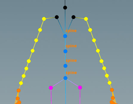
Spine tags -
The APEX Autorig Component SOP,
spine, adds spline functionality to Electra. On thespinenode, set the Component Source parameter to Spline. -
In the Driven tab, set Driven to
#spine. -
Set the parents of the spine controls in the Parent tab - set both Root and Tip to
Cog, a control we previously added. -
Change the control shape in the Shape tab.
-
View the spine functionality in the animate state:
IK 
We now add IK functionality to the arms and legs using the multi IK rig component:
-
On the Attribute Adjust Array SOP, add tags for the arms and legs -
L_arm,R_arm,L_leg, andR_leg. These tags are picked up by the multi IK rig component.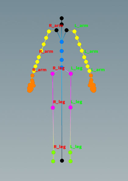
Arm and leg tags Note
On Electra’s arms, there are two joints at both the shoulder and elbow - one is the regular skeleton joint, and the other is a twist joint:
-
Shoulder joints -
*_upperarm and*_upperarm_01_twist -
Elbow joints -
*_lowerarm and*_lowerarm_05_twist
Make sure you are not tagging the twist joints at the shoulder and elbow. On the Attribute Adjust Array SOP, check that the list of joints in the Operation parameter doesn’t include
*twistjoints. For example, for tagL_arm, Operation should be set to@name=L_upperarm @name=L_lowerarm @name=L_hand, not@name=L_upperarm_01_twist @name=L_lowerarm_05_twist @name=L_hand. -
-
The APEX Autorig Component SOP,
ik, adds IK functionality to Electra. On theiknode, set the Component Source parameter to Multi IK. -
In the Driven tab, set Segments to the tags we want to add IK to. In our example, we set Segments to
*arm *leg.Note
The Segments parameter does not take APEX path patterns, for example, the
#tagfunction. Instead, specify the tag names directly in this field. -
In the Parent tab, set Tip to
Main. If Pole Vector is empty, the pole vector is parented to the tip. -
Change the control shape in the Shape tab.
-
View the IK behavior in the animate state:
Twist 
We now add twist functionality to the arms using the twist rig component:
-
On the Attribute Adjust Array SOP, add twist tags for the arms. There must be a separate set of tags for each section of the arm - from the shoulder to the elbow, and from the elbow to the hand. Twist tags must be added to the root joint, the tip joint, and the twist joints between the root and tip (including the twist joint at the root). These tags are picked up by the twist rig component:
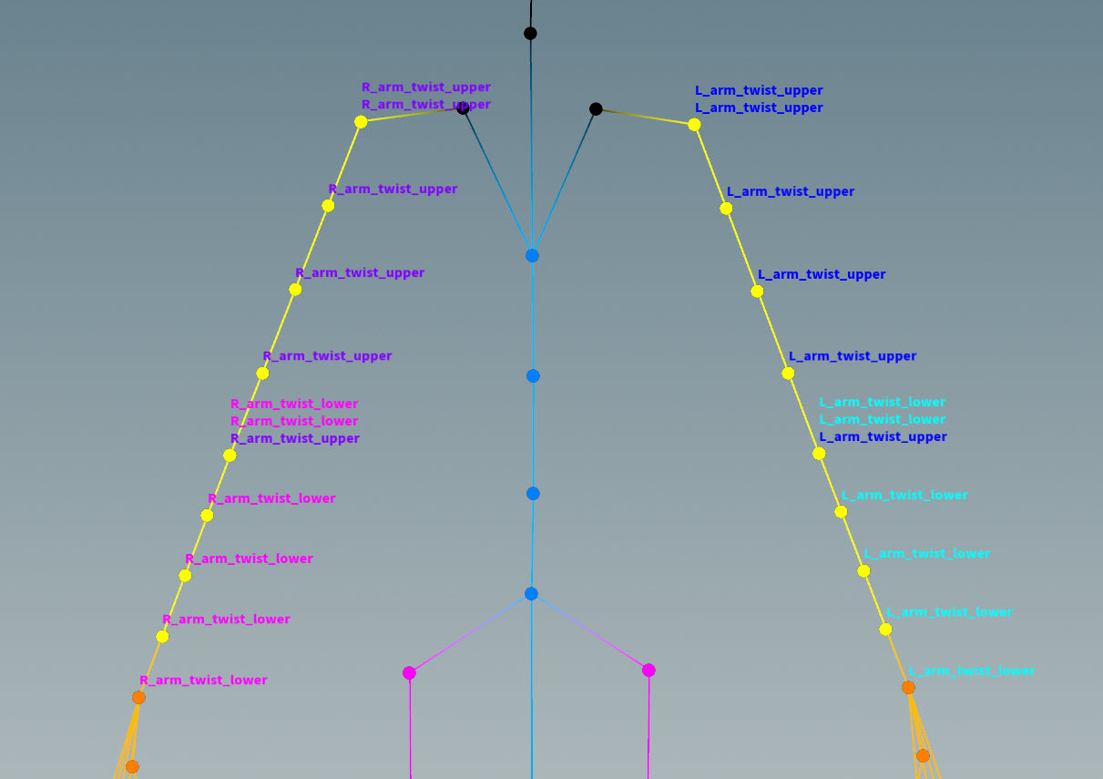
Twist tags Note
There could be twist joints at the same location as a root or tip joint. On the Attribute Adjust Array SOP, check the list of joints in the Operation parameter to make sure you are tagging the correct joints.
Taking Electra’s left upper arm, for example, Operation should be set to:
-
Root joint -
@name=L_upperarm -
Tip joint -
@name=L_lowerarm -
Twist joints between the root and tip, including the twist joint at the root -
@name=L_upperarm_01_twist @name=L_upperarm_02_twist @name=L_upperarm_03_twist @name=L_upperarm_04_twist
See the twist component for more information on how to tag joints for the twist component.
To see the skeleton joint names:
-
On Attribute Delete SOP, Point Attributes parameter, remove the
propertiesvalues that was previously added. -
Select the APEX Autorig Component SOP,
fk, turn on its display flag, and click Animate on the left toolbar.
-
-
The APEX Autorig Component SOP,
twist, adds twist functionality to Electra’s arms. On thetwistnode, set the Component Source parameter to Twist. -
In the Driven tab, set Segments to the tags we want to add twist functionality to. In our example, we set Segments to
*arm_twist*. -
Pin the root of the upper arm joint chain (shoulder joint) to see the effect of the twist functionality. If you don’t pin the root, all the twist joints will rotate by the same amount.
-
Add a
pintag to the upper segment of the arms - on the Attribute Adjust Array SOP, for theL_arm_twist_upperandR_arm_twist_uppermultiparms, click beside Values, and set the new Value parameter to pin.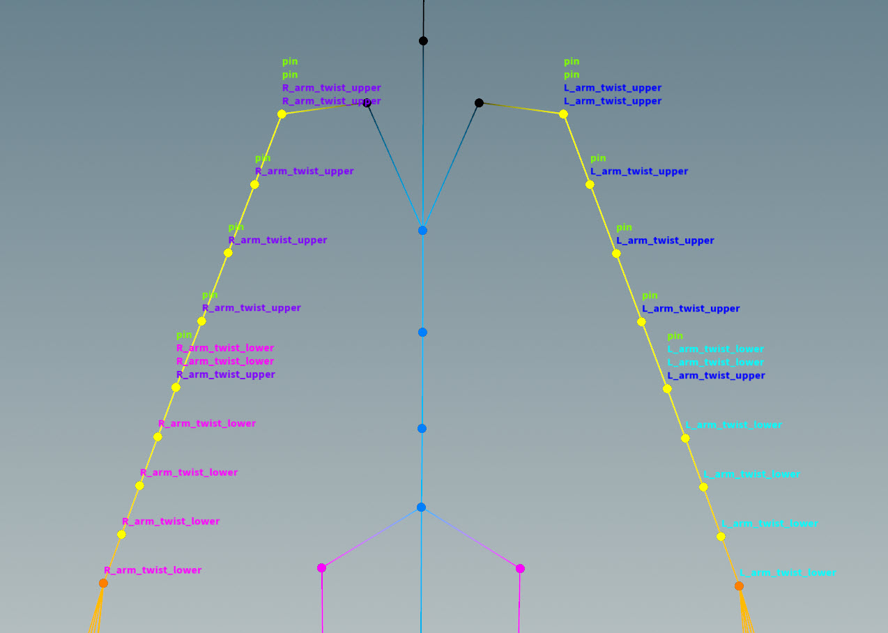
-
On the APEX Autorig Component SOP,
twist, Settings tab, turn on Pin Root and set Pin Tag topin. The pink control added at the root of the joint chain is the up vector of the pin.Root not pinned (left), root pinned (right)
-
IK/FK blend 
We now add functionality to blend between IK and FK for the arms and legs using the IK/FK blend rig component:
-
The APEX Autorig Component SOP,
ikfkblend, adds IK/FK blend functionality to Electra. On theikfkblendnode, set the Component Source parameter to IK / FK Blend. -
In the Driven tab, set Segments to the tags we want to add IK/FK blending to. In our example, we set Segments to
*arm *leg. -
View the IK/FK blend behavior in the animate state:
Note
The IK/FK blend control consists of two parts - an abstract control that drives the blend value between IK and FK, and a position control that allows you to move the abstract control around:
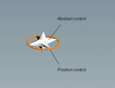
IK/FK blend control If Use Click and Drag in the handle parameters is turned off, you need to first select the abstract control, then drag to see the effects of the IK/FK blend. If Use Click and Drag is turned on, you can click and drag the abstract control in one step.
Reverse foot 
We now add reverse foot functionality using the reverse foot rig component:
-
On the Attribute Adjust Array SOP, add tags for the foot (
L_foot,R_foot), ball joints (ball), and ankle joints (ankle). These tags are picked up by the reverse foot rig component: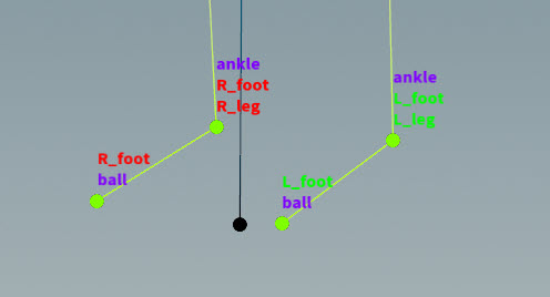
-
On the APEX Autorig Component SOP,
reverse_foot, set the Component Source parameter to Reverse Foot. -
In the Driven tab:
-
Set Segments to
*foot. -
By default, Ankle is set to
#ankle, and Ball is set to#ball. These match the tag names on Electra. -
The IK Driven parameter is set to
#ik_tipby default, whereik_tipis a tag that was added by the multi IK rig component upstream (in the Tags tab, Target parameter).
-
-
In the Parent tag, set Root to
Main, the root control created by the transform driver component upstream. -
View the reverse foot behavior in the animate state:
Tip
The following hotkeys change the drag behavior of abstract controls (white ball in front of the toe) in the viewport:
Drag behavior
Action
Change abstract control values by an integer step size
Hold ⌃ Ctrl while dragging.
Change abstract control values at a slower rate
Hold ⇧ Shift while dragging.
Change abstract control values at a faster rate
Hold ⌃ Ctrl + ⇧ Shift while dragging.
Adding toe joints 
Electra’s skeleton doesn’t have toe joints, but the reverse foot component automatically creates a toe, so you don’t need to specify anything in the Driven tab, Toe parameter. If you want to add your own toe joints:
-
Add toe joints using a
 Rig Attribute VOP SOP:
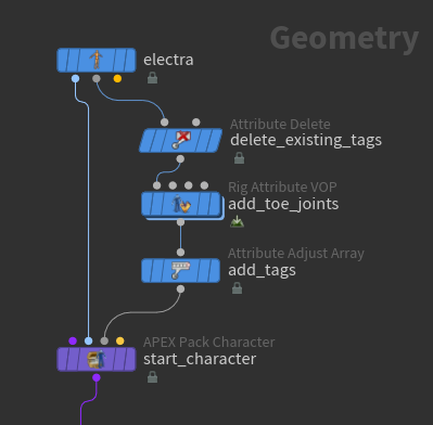
-
In the Rig Attribute VOP SOP, use Electra’s ball joints as a reference for creating toe joints. See adding extra joints for how to build the network below:
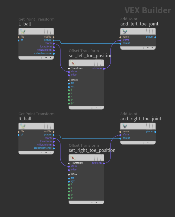
Add toe joints in the Rig Attribute VOP SOP -
Set the positions of the toe joint by adjusting the Translate parameter on the
 Offset Transform VOPs.
 -
On the
 Add Joint VOP for the left toe, set Name to
 L_toe. Similarly, set the Name parameter on the right Add Joint VOP toR_toe: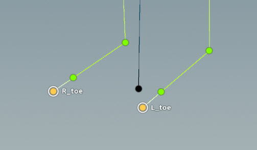
Added toe joints -
On the Attribute Adjust Array SOP, add tags
toe,R_Foot, andL_Footto the toe joints: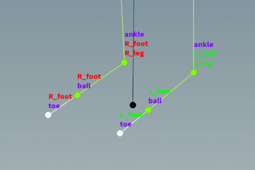
-
On the APEX Autorig Component SOP,
reverse_foot, Driven tab, set Toe to#toe. -
In the Settings tab, adjust the Toe Offset and Toe Control Offset as necessary.
Look at 
We now add look at functionality using the look at rig component:
-
On the Attribute Adjust Array SOP, add a tag for the head. This tag is picked up by the look at rig component.
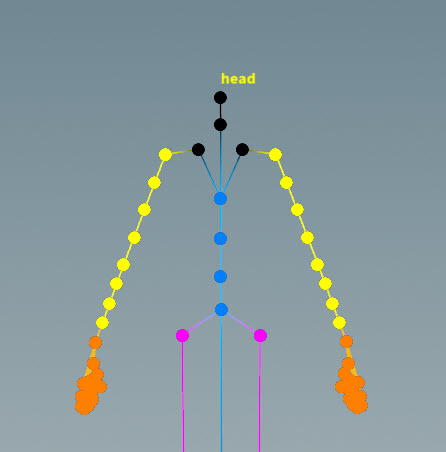
Head tag -
On the APEX Autorig Component SOP,
lookat, set the Component Source parameter to Look At. -
In the Driven tab, set Driven to
#head. This is the joint that is driven by the look at control. -
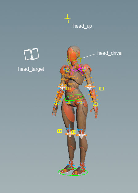
Set the names for the head, target, and up controls in the Driven tab. We set Driver to
head_driver, Target tohead_target, and Up tohead_up. -
Only promote the rotation of the head driver so you can’t detach Electra’s head - in the Driven tab, turn on Driver Promote R and turn off Driver Promote T.
-
Set the position of the target control - in the Settings tab, turn on World Space, and adjust Target Position.
-
Set the position of the up control:
-
In the Driven tab, turn on Use Up to display the up control in the viewport.
-
In the Settings tab, adjust Up Position.
-
-
Set the scale and color of the controls in the Shape tab:
-
View the look at behavior in the animate state:
Configure controls 
Use the ![]() APEX Configure Controls SOP to configure the shapes and colors of the controls:
APEX Configure Controls SOP to configure the shapes and colors of the controls:
-
On the APEX Configure Controls SOP, add configurations for different groups of controls by clicking
beside Control Configs. -
Specify the controls to configure - in the Control Group parameter, choose from the drop-down list or use the APEX path pattern syntax to specify groups of TransformObject nodes.
-
For each group of controls in the Control Configs multiparm, turn on the Use Shape Override, Use Shapeoffset, and Use Color parameters, and specify the desired control shape, size, and color.
After configuring the controls, we are finished building the rig for Electra:
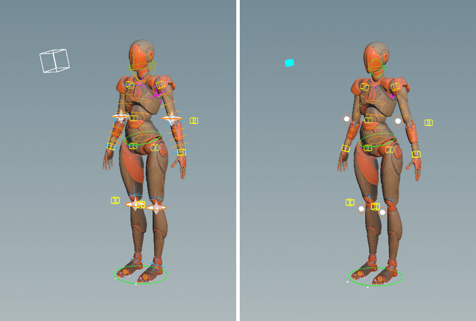
Before (left) and after (right) configuring controls
Add Electra to an animation scene 
Add Electra to an animation scene using the ![]() APEX Scene Add Character SOP and
APEX Scene Add Character SOP and ![]() APEX Scene Animate SOP. See animation workflow for more information.
APEX Scene Animate SOP. See animation workflow for more information.
Full body IK 
In this example, we add full body IK to Electra using the full body IK rig component:
-
On the Attribute Adjust Array SOP, add the tag,
fbik, to joints like the feet, pelvis, wrists, and neck. This tag is picked up by the full body IK rig component: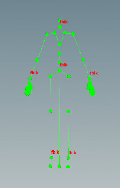
-
On the APEX Autorig Component SOP,
fk, remove all the entries for T Promote Group, R Promote Group, and S Promote Group in the Controls tab. -
On the APEX Autorig Component SOP,
fbik, set the Component Source parameter to Full Body IK. By default, the Drivers parameter in the Drivers tab is set to%tag(fbik), so the joints tagged withfbikdrive the full body IK behavior. -
View the full body IK behavior in the animate state: