| On this page |
 APEX Autorig Component SOPは、色々な方法で独自のカスタムツールを作成することができます。
例えば、リグコンポーネントスクリプトを使用したり、APEX Scriptスニペットを受け入れるビルトインのコードインターフェースを使用したり、グラフのリグ機能を既存のリグにマージすることができます。
APEX Autorig Component SOPは、色々な方法で独自のカスタムツールを作成することができます。
例えば、リグコンポーネントスクリプトを使用したり、APEX Scriptスニペットを受け入れるビルトインのコードインターフェースを使用したり、グラフのリグ機能を既存のリグにマージすることができます。
APEX Scriptを使用して独自機能を作成する 
APEX Autorig Component SOPには、APEX Scriptコードを記述するためのインターフェースが備わっています。 APEX Autorig Component SOPで、 Component Source を Snippet に設定します。 Snippet パラメータにAPEX Scriptコードを入力して、そのスクリプトの機能を独自のリグコンポーネントとして保存することができます。
グラフ機能を既存のリグにマージする 
APEX Autorig Component SOP内でFuseグラフオペレーションを使用すると、(Fuseグラフと呼ばれる)グラフを既存のリグにマージすることができます。 この方法では、キャラクタリグから始めて、更新したいリグの部分を抽出して、APEXネットワークビュー内でその機能を編集してから、その更新内容をリグにマージして戻すことが可能です。 この方法では、モジュール方式のワークフローでリグに変更を加えることができます。
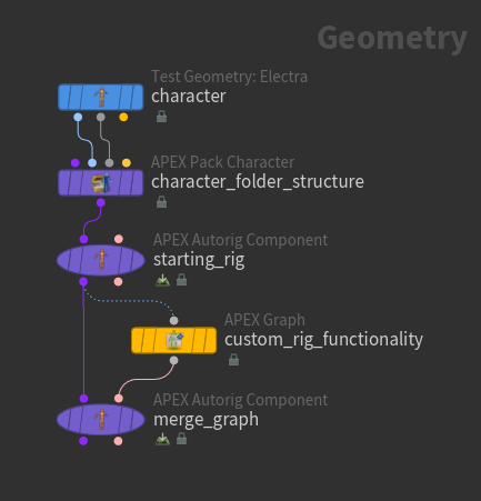
Fuseグラフオペレーションは、 APEX Graph SOPで導入された新しいノードを追加、接続します。
Fuseグラフオペレーションは、ノードを接続し直したり、削除することはしません。
APEX Graph SOPで導入された新しいノードを追加、接続します。
Fuseグラフオペレーションは、ノードを接続し直したり、削除することはしません。
Note
Fuseグラフ(APEX Graph SOP)内のサブネットに新しいノードを配置することは推奨されていません。 後でそのサブネットの名前を変更すると、そのグラフは機能しなくなります。 また、Fuseグラフオペレーションは、Fuseグラフ内の既存のノードを新しいサブネットに追加することができません。 ただし、既存のリグに対して完全に新しいサブネットを挿入することは可能です。
このページでは、以下のFuseグラフオペレーションの使い方を説明しています:
-
コントロールシェイプをリグに追加する。
-
カスタムのIK機能をリグに追加する。
コントロールシェイプを追加する 
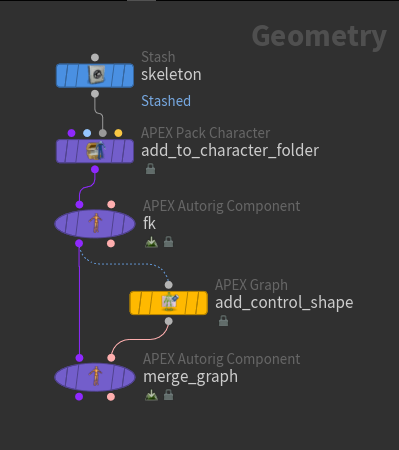
この例では、キャラクタの背骨のジョイントにコントロールシェイプを追加します:
-
まず最初に
 APEX Pack Character SOPを使用して、キャラクタのスケルトンをキャラクタフォルダ構造に追加します。
 -
FKリググラフを作成します。
APEX Autorig Component SOP(fk)で、 Component Source を FK Transform に設定します。FKトランスフォームコンポーネントの詳細は、単純なジオメトリのリギングとキャラクタリギングを参照してください。FKリググラフは、APEXネットワークビューで確認することができます。 緑色のノードは、スケルトンのジョイントを表現した
 TransformObjectノードです:
FKリググラフ -
APEX Graph SOP内でFuseグラフを構築します。
そのAPEX Graph SOPは、キャラクタフォルダ構造を受け取って、そのキャラクタフォルダ構造内のリググラフを自動的に検索することができます。
また、 Graph Path パラメータを設定することで、キャラクタフォルダ構造にある特定のリグを検索するようにAPEX Graph SOPに指示することも可能です。
APEX Graph SOPに開始点となるグラフが入力されると、APEXネットワークビューでそのグラフを手動で編集できるようになります。
この例では、APEX Graph SOPに、FKリググラフ全体のコピーが開始点として含まれています。 この状態から、APEXネットワークビューでの作業が容易になるように、グラフを簡素化することも可能です。
-
APEX Graph SOPを選択し、APEXネットワークビューに移動して手動でグラフを更新します。 新しい
rig::ControlShapeノードを背骨のTransformObjectノードの1つに接続することで、コントロールシェイプを背骨ジョイントに追加します: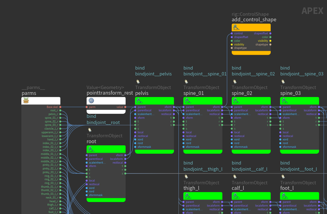
背骨のコントロールシェイプを追加 -
rig::ControlShapeノードを選択して、APEXネットワークビュー内でPを押してノードパラメータウィンドウを開きます。 color を(1,0,0)、 shapetype をbox_wiresに設定します。 -
Animateステートでは、APEXネットワークビュー内でグラフを更新する時、ビューポート上でリグの視覚的な表現を確認することができます。Animateステートに入るには、APEX Graph SOPを選択して、そのDisplayフラグをオンにして、左側のツールバーにある
 Animateをクリックします:
元のリグ(左)、背骨のコントロールシェイプを追加(右) -
APEX Graph SOPからのグラフを元のFKリググラフにマージします。2つ目のAPEX Autorig Component SOPの
merge_graphで、 Component Source を Fuse Graph に設定します。Fuseグラフオペレーションが新しいノードを検索し、それを元のグラフに接続します。APEX Autorig Component SOPの
merge_graphのAPEXネットワークビューで、1つ目のAPEX Autorig Component SOPのfkからのFKリググラフに、rig::ControlShapeノードが追加されます。新しいノードは緑色です:
新しいノードで更新されたFKリググラフ
グラフを簡素化する 
変更がリグの特定の部分にのみ影響する場合は、変更に関係のないTransformObjectノードを削除することで、グラフを簡素化することができます:
-
開始点として、APEX Graph SOPには前の例からのFKリググラフが含まれています。
spine_01ノードを除くすべてのTransformObjectノードを削除します: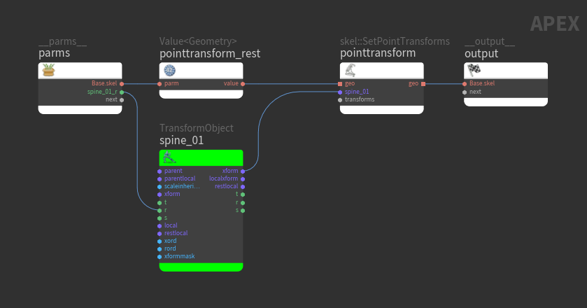
 skel::SetPointTransformsノードの詳細は、ジオメトリ変形のためのグラフを参照してください。
 -
このプロセスでは
spine_01の親を削除してしまっているため、スケルトン上の適切な位置にジョイントを配置し直す必要があります:-
APEX Graph SOPの Rigging Scripts セクションで、 Update Rest Transforms From Skeleton をクリックします。
-
APEX Graph SOPでAnimateステートに入り、背骨ジョイント上のTransformObjectノードを確認します:

-
-
新しい
rig::ControlShapeノードを背骨のTransformObjectノードに接続することで、背骨ジョイントにコントロールシェイプを追加します。-
rig::ControlShapeノードを選択します。 -
ノードパラメータウィンドウで、 color を
(1,0,0)、 shapetype をbox_wiresに設定します。

追加したコントロールシェイプはAnimateステートで確認することができます:

-
-
APEX Autorig Component SOPの
merge_graphにおけるFuseグラフオペレーションは、新しいノードのrig::ControlShapeを検索し、それを元のFKリググラフのspine_01TransformObjectノードに接続します。
カスタムのIK機能を追加する 
Fuseグラフオペレーションでは、キャラクタのリグの様々な部分に適用可能な、柔軟性の高いツールを作成することができます。 この例では、キャラクタの脚にIK機能を追加するFuseグラフを手動で構築します。その後、そのIK機能をキャラクタの両腕にミラーおよび転送します:

-
APEX Graph SOPで、キャラクタの脚のIK機能を含んだFuseグラフを手動で構築します。
Note
Fuseグラフ内のTransformObjectノードの名前は、入力スケルトンのジョイント名に合わせてください。
APEX Graph SOPを選択して、そのDisplayフラグを有効にして、Animateステートに入ります:
-
APEX Autorig Component SOPの
merge_graphで、 Component Source を Fuse Graph に設定します。Fuseグラフオペレーションにより、新しいIK機能が元のFKリググラフに追加されます。 -
APEX Autorig Component SOPの
merge_graphを選択し、そのDisplayフラグをオンにして、Animateステートに入ります。 -
IK機能をリグの両側にミラーされるように設定します。リグで、ジョイントには
<joint>_lや<joint>_rという名前が付けられているので、 From と To パラメータを*_lと*_rに変更します。 Mirror パラメータは既にオンになっているので、正確なジョイント名のマッピングが設定されると、デフォルトでミラーリングが実行されます:
両脚にミラーリングされたIK機能 -
これで、IK機能を腕などの他のジョイントチェーンへ転送することができます。 Mapping の横にある
 をクリックし、IKチェーンのルート、中間、先端の各ジョイントに対して1つずつ、計3つのマッピングを追加します。マッピングは、スケルトンジョイントを表すTransformObjectノード間で行なわれます。
 -
マッピングする各ジョイントについて:
-
From パラメータの横にある
 アイコンをクリックします。これは、既存の機能が設定されているジョイントです。
 -
ビューポートでジョイントを選択してEnterを押します。これにより、 From パラメータにそのジョイント名が入力されます。
Note
ジョイントを選択します。ジョイント上のコントロールではありません。
-
To パラメータの横にある
アイコンをクリックします。これは、機能を適用したいジョイントです。 -
ビューポートでジョイントを選択してEnterを押します。これにより、 To パラメータにそのジョイント名が入力されます。
この例の場合、3つのマッピングは以下の通りです:
-
From =
thigh_l、 To =upperarm_l -
From =
calf_l、 To =lowerarm_l -
From =
foot_l、 To =hand_l
-
-
IK機能が両腕に配置されています:

リグ機能を保存して再利用する 
カスタムのリグ機能を独自のリグコンポーネントとして保存したら、事前構築済みコンポーネントと同じように再利用することができます:
-
APEX Autorig Component SOPで、 Save タブに移動します。 Save タブは、 Component Source が Use Second Input 、 Snippet 、 Fuse Graph に設定されている時に利用可能です。
-
Component Name パラメータでコンポーネントの名前を指定します。例えば、ネームスペースフィールドを
testに、名前フィールドをhello、バージョンを2.0に設定した場合、コンポーネント名はtest::hello::2.0になります。 -
他にも、Autorig BuilderのComponent Catalog HUDに表示されるコンポーネントのラベル( Component Label )やそのコンポーネントのアイコンとして使用される
.pngファイル( Component Icon )を指定することもできます。 -
Component Output File で、コンポーネントの保存先となるパスを設定します。このファイルは
$HOUDINI_PATH/apexcomponent/<component_name>.bgeoに保存してください。 -
Save to Disk をクリックします。
-
Component Source パラメータの横にある
 をクリックし、コンポーネントのライブラリを更新します。新しいコンポーネントが Component Source ドロップダウンメニューに表示され、他のコンポーネントと同じように使用することができます。
 -
Component Source ドロップダウンメニューで新しいコンポーネントを選択すると、そのソースをAPEX Scriptスニペットとして編集できるようになります。 Component Source の横にある
 をクリックすると、コンポーネントが Snippet パラメータに逆コンパイルされ、コンポーネントにさらに変更を加えることができます。
 Note
Fuse Graph オペレーションを使用して作成されたコンポーネントの場合は、 Settings ▸ Header セクションに移動し、 Template を Fuse Graph に設定します。
Autorig Builder用コンポーネントの準備 
APEX Autorig Component SOPでは、 Rig Builder タブのパラメータを用いることで、カスタムコンポーネントをAutorig Builderのインタラクティブツールとして利用可能にすることができます。 Rig Builder タブは、 Save タブの Use with Rig Builder が有効になっている時に利用可能です。
Autorig Builderで使用するカスタムコンポーネントを準備するには:
-
必要に応じて、コンポーネントの適用先が指定された“segments”パラメータを定義します。 Autorig Builderは、“segments”キーワードを認識し、ユーザがドラッグアンドドロップ操作によってキャラクタの色々な部分にコンポーネントを適用できるようにします。 APEX Scriptでは、以下のように“segments”パラメータを定義することができます:
segments: String = BindInput('', preset='tags')APEXグラフを使用してコンポーネントを作成する場合、“segments”は入力パラメータとして用意します。
-
Rig Builder タブで、Autorig Builderの
ギアメニューに表示させたいコンポーネントの入力パラメータを指定します:-
Generate from Component Parms をクリックすると、パラメータインターフェースにあるコンポーネントのパラメータが Config Control Parms マルチパラメータに自動入力されます。 APEX Scriptの場合、
BindInput()を使用して入力パラメータを定義してから、ボタンをクリックし、それらのパラメータをパラメータエディタに表示させます。
詳細は、グラフインターフェースの作成を参照してください。または
-
Config Control Parms マルチパラメータにそれらのパラメータを手動で追加します。
Config Control Parms で指定されていないコンポーネントパラメータの場合(例えば、
BindInput()を使用してパラメータを定義した場合)、Autorig Builderはそれらのパラメータに設定されているデフォルト値を使用します。 -
-
Drag Drop Interaction を Skeleton に設定します。
-
Skeleton Source を設定します。
-
Joint Group パラメータで、 Skeleton Source 内のコンポーネントに関連するジョイントを選択します。 例えば、腕に機能を追加するコンポーネントを構築する場合、このパラメータには、キャラクタの左側の腕のジョイントのみを含める必要があります。 これらのジョイントは、Autorig Builderでドラッグアンドドロップ操作を実行した時の参照スケルトンとして使用されます。
-
Remove Side Indicator を設定します。 これによって、ジョイント名から“側”の表記が除去され、コンポーネントがキャラクタの両側で使用できるようになります。
-
コンポーネントを保存します。
-
 APEX Autorig Builder SOPで、
 アイコンをクリックして、リグコンポーネントのライブラリを更新します。
新しいコンポーネントがComponent Catalog HUDに表示され、他のコンポーネントと同様にガイドキャラクタ上にドラッグアンドドロップできるようになります。
アイコンをクリックして、リグコンポーネントのライブラリを更新します。
新しいコンポーネントがComponent Catalog HUDに表示され、他のコンポーネントと同様にガイドキャラクタ上にドラッグアンドドロップできるようになります。
Fuseグラフを使用して作成されたコンポーネント 
この例では、Autorig Builderで使用できるように上記のIK脚機能を準備します:
-
APEX Autorig Component SOPの Save タブで、 Use with Rig Builder を有効にします。
-
Drag Drop Interaction を Skeleton に設定します。
-
Skeleton Source を From Guide Skeleton に設定します。これによって、 Guide Skeleton で指定されたスケルトンが使用されます。
-
Joint Group パラメータで、コンポーネントが適用されるジョイントを選択します。これらのジョイントは、Fuseグラフの
TransformObjectノードのデフォルト位置を決めます。Fuseグラフ内のTransformObjectノード名は、入力スケルトンのジョイント名と一致している必要があります:-
Joint Group の横にある
 ボタンをクリックします。
 -
Rig Treeビューで、ジョイントを選択します。この例では、
thigh_l、calf_l、foot_lです。 -
Accept をクリックします。
選択したジョイントが Joint Group パラメータに設定されます。
-
-
Remove Side Indicator を
*_lに設定します。これによって、ジョイント名から*_lが除去され、コンポーネントがキャラクタの両側で使用できるようになります。 -
コンポーネントを保存します。
-
APEX Autorig Builder SOPで、アイコンをクリックして、リグコンポーネントのライブラリを更新します。
新しいコンポーネントがComponent Catalog HUDに表示され、ガイドキャラクタ上にドラッグアンドドロップできるようになります。