| Since | 21.0 |
This component sets up the controls that move a character’s scapula:
The following is an example network for setting up the scapula component:
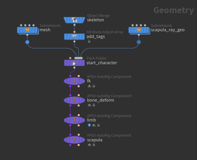
-
The inputs are the character’s mesh and skeleton, and a scapula ray geometry:
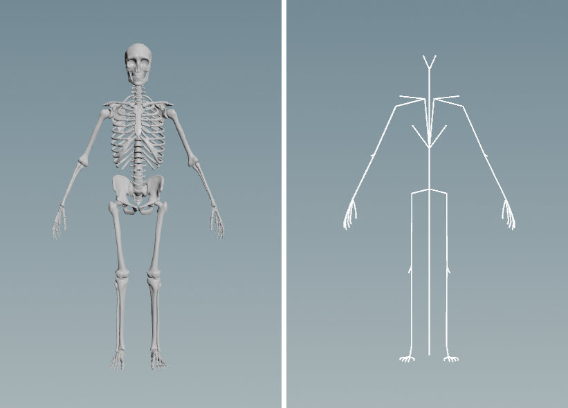
Mesh (left), skeleton (right) The scapula ray geometry is a geometry surface that the look at target for the scapula control is projected onto (see the steps below for more details):
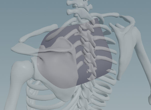
Scapula ray geometry -
The scapula component requires clavicle and scapula joints on the skeleton:
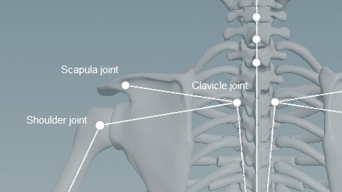
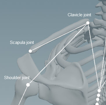
Joints needed for the scapula component -
Add scapula tags to the clavicle, scapula, and shoulder joints using the
 Attribute Adjust Array SOP (see preparing skeletons for more information on tagging skeleton joints):
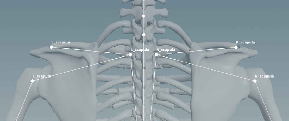
Scapula tags -
Add the mesh, skeleton, and scapula ray geometry to a character folder structure using a
 Pack Folder SOP. See assembling data for more information on using this node.
 On the Pack Folder SOP, specify a name for the scapula ray geometry. In our example, we name the geometry
ScapulaRay.shp(we set Name toScapulaRay, and Type toshp). -
See rigging a character for how to use the fk transform and bone deform rig components.
-
The limb rig component sets up the clavicle controls needed by the scapula component.
-
On the scapula component, set the following:
-
In the Settings tab, set Ray Geometry to the name of the scapula ray geometry in the character folder structure, in our case,
ScapulaRay.shp. -
In the Driven tab, set Segments to the scapula tags, in our case,
*_scapula.
The following scapula controls are created:
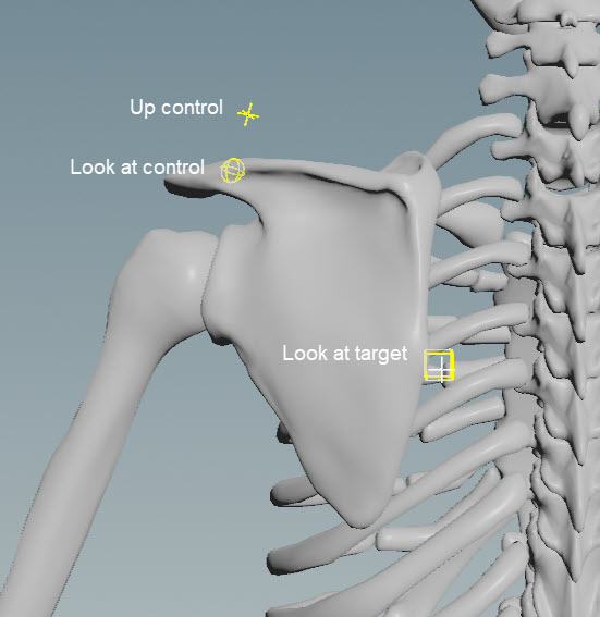
Scapula controls -
-
At the look at target, there is a box control that you can move around and a cross indicator that is projected onto the scapula ray geometry. The look at control (sphere) looks at the cross indicator, not the box control, and the cross indicator stays within the extents of the scapula ray geometry:
Drive the scapula with the look at target control You can also drive the scapula with the clavicle target control. When you move the clavicle target, the scapula moves along with it, and the shoulder follows the rotation of the scapula:
Drive the scapula with the clavicle target control
Parameters 
Name
The name to add to the subnet nodes that set up the scapula look at functionality.
Settings 
Ray Geometry
A shape onto which the scapula look at target is projected. This can be a polygon surface or NURBS curves, but a polygon surface is recommended, as NURBS could affect the performance if you have a heavy mesh.
Target Position
The start position of the scapula look at target.
Up Position
The position of the scapula look at up vector.
Clav U Range
The minimum and maximum rotation of the clavicle, in degrees, which determine the U range of the scapula look at target. As the clavicle rotation moves from the min to the max rotation value, the look at target moves from Target Position to Target U Max Offset. These values are automatically mirrored on the other side of the rig.
Target U Max Offset
The maximum offset of the scapula look at target from the Target Position in the U direction. When the clavicle rotation is at its maximum value (in Clav U Range), the look at target is at this offset. This value is automatically mirrored on the other side of the rig.
Clav V Range
The minimum and maximum rotation of the clavicle, in degress, which determine the V range of the scapula look at target. As the clavicle rotation moves from the min to the max rotation value, the look at target moves from Target Position to Target V Max Offset. These values are automatically mirrored on the other side of the rig.
Target V Max Offset
The maximum offset of the scapula look at target from the Target Position in the V direction. When the clavicle rotation is at its maximum value (in Clav V Range), the look at target is at this offset. This value is automatically mirrored on the other side of the rig.
Driven 
Segments
Segments are tags that separate each scapula setup. For example, *_scapula loops over tags L_scapula and R_scapula. Tags can be set up on skeleton joints using an ![]() Attribute Adjust Array SOP. See preparing skeletons for rigging for more information.
Attribute Adjust Array SOP. See preparing skeletons for rigging for more information.
If Segments is empty, the scapula logic is run once.
Note
The Segments parameter does not take APEX path patterns, for example, the #<tag> function. Instead, specify the tag names directly in this field.
IK Control
The IK root control for the shoulder. This control is parented to the scapula. When the scapula moves, the shoulder moves along with it. This parameter accepts APEX path patterns.
Parent 
Parent
The parent of the clavicle controls. This is the usually the chest control.
Tags 
Shape 
The ![]() APEX Configure Controls SOP provides more options for changing the look of the controls.
APEX Configure Controls SOP provides more options for changing the look of the controls.
Color
The color of the control shapes.
Scale
The scale of the control shapes.
| See also |