| On this page |
|
| Since | 21.0 |
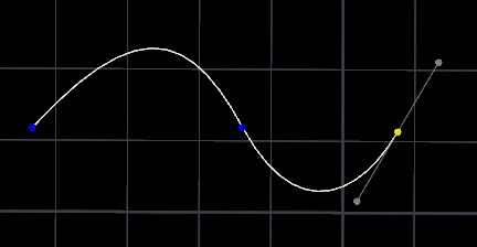
This node’s interactive state lets you draw and edit cubic Bézier curves using tools similar to 2D illustration programs like Illustrator, Sketch, and InkScape. This is useful for drawing artistic curves by hand. For example, tracing images, drawing logos, and drawing profile curves to extrude and revolve.
While drawing a Bézier curve, you can insert arc segments. Technically the arcs are not perfectly round, because this node does not create weighted Bézier curves.
This node also includes an Auto-Bézier mode, similar to Illustrator’s Curvature tool, which lets you guide a curve by placing edit points without having to worry about tangents.
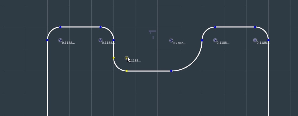
You can set corners as rounded and control the radius of each corner with a draggable grip. These corners remain editable while you use the node, then are baked into the curves.
You can also use this node to draw polylines, non-cubic orders of Bézier curves, and NURBS. However, when you are drawing these other types, you simply click to place each point and Houdini interprets the point according to the curve type, without the special support for drawing tangents you get when drawing cubic Bézier curves.
Terms 
Edit points
Also called on-curve points, breakpoints, or knots. In a cubic Bézier curve, the curve passes through these points.
Tangent handles
Also called control points. In a cubic Bézier curve, these control the direction of the curve going into and coming out of an edit point.
Corner point
An edit point where the tangents have zero length or point in different directions, causing a sharp corner. This is sometimes called having broken tangents.
Smooth point
An edit point where the node keeps the tangents together in a line, so the curve has smooth tangent continuity as it goes through the point.
Balanced point
An edit point where the node keeps the tangents together in a line, and also enforces that the tangent points are equal distance from the edit point, so the curve has smooth curvature continuity as it goes through the point.
Auto Point
An edit point where the tangents are automatically computed based on the positions of surrounding points and tangents to create a smooth curve.
Branch point
An edit point containing multiple vertices.
Modes
While the Curve tool’s state is active, you can be in one of four modes: the Pen (drawing) mode, the Edit mode, the Auto-Bezier mode, or the Orient mode. The buttons for these modes are in the operation toolbar across the top of the viewer when the node’s state is active.
Using the interactive state 
-
With the Curve node selected, click the
 Handles tool (to the left of the viewer), or move the mouse over the viewer and press Enter.
The Handles tool lets you interact with the current node’s state/handles in the viewer. You can switch between the Handles tool and other tools (View, Select, Move, Rotate, Scale) to change the view and manipulate objects in the scene.
-
Because of how Houdini works, pressing ⎋ Esc switches from the Handles tool to the View tool. This can be confusing if you just meant to cancel drawing. To get back to the Handles tool (and the curve node’s state), make sure the Curve node is still selected, move the mouse over the viewer, and press Enter.
How to 
This section outlines how to use the different modes while in the interactive state.
Drawing Bézier curves 
In Draw mode, click or drag in empty space to start a new curve, or click/drag an the start or end point of an existing curve to continue drawing the curve.
| To... | Do this |
|---|---|
|
Place a corner point |
|
|
Place a smooth point |
|
|
Switch from a smooth curve to a straight line |
|
|
Switch from a straight line to a smooth curve |
|
|
Draw two curve segments connected by a corner (broken tangents) |
|
|
Add an arc segment |
|
|
Edit points while drawing |
|
|
Begin drawing from branch point |
|
|
Finish the curve |
|
|
Draw on a surface geometry |
|


Drawing with the Auto-Bézier mode 
In Auto-Bézier mode, you can only click to place points (there are no tangent handles). The relative placement of the points controls the direction and curvature of the curve. The preview shows the new shape of the curve if you add a point at the current pointer location.
With some practice, you can learn how to place points (closer together or farther apart) to control the curve’s turning speed and its shape.
| To... | Do this |
|---|---|
|
Add a point |
|
|
Finish the curve |
|
Editing curves 
| To... | Do this |
|---|---|
|
Select a point or points using the Edit mode |
|
|
Make a smooth point into a corner (break tangents) |
|
|
Change points from corner to smooth to balanced |
|
|
Reshape a Bézier curve |
Do any of the following:
|
|
Move a point |
|
|
Move a point in 3D space |
|
|
Move an entire curve |
|
|
Copy and paste a curve |
|
|
Insert a point in the curve |
|
|
Cut a curve at a point |
|
|
Join two open endpoints |
|
|
Join two open endpoints with a line |
|
|
Delete a point |
|
|
Delete a curve segment |
|
|
Make a corner rounded |
|
|
Reverse a curve |
|
|
Clear all curves |
|

Creating an Orient Attribute 
In Orient mode, you can specify target orientation on anchor points by specifying a target Up vector and (optionally) also a Tangent vector. Attributes for the orientations are then created to smoothly transition in and out of the specified orientations. The resulting attributes use a parallel transport along the curve to determine the orientation for all other points.
To output the orient or axis attributes, turn on Output Orient Attribute, Output X Axis, Output Y Axis, or Output Z Axis. When any of these attributes are on, guide geometry is drawn on curves in the viewport to visualize the attribute. There are state parameters available to turn on this guide, as well as control the density and scale of guide gnomons.
When in orient mode, interactive gadgets are available on each of the points with a target orientation. By dragging these gadgets, you can rotate the frame around the curve tangent at the point.
| To... | Do this |
|---|---|
|
Add a target orientation point |
or
|
|
Remove a target orientation point |
or
|
|
Show the full rotation handle for a target orientation point |
|
Operation toolbar 
Primitive Type |
Sets what kind of curve(s) this node creates. |
||
|
Edit mode |
F |
Edit existing curves. See editing curves. |
|
Draw mode |
G |
Draw new curves. See drawing curves. |
|
Auto-Bézier mode |
H |
Draw Bézier curves using a simpler path guiding method. See using Auto-Bézier. |
|
Orient mode |
O |
Create an orient attribute on curves. See creating an orient attribute. |
|
Delete Point |
⌦ Del |
Deletes the selected point (if any). |
|
Join Selected Points |
Joins the selected end vertices (if any) into a single vertex. If the two end vertices belonged to separate curves, the result is a single merged curve. |
|
|
Cut Curves at Selected Points |
Cuts the selected point (if any) into two separate points. Depending on where the point is, it may also cut the curve into two curves. |
|
|
Add Segment Between Points |
Inserts a new straight segment between the two selected endpoints (if any). |
|
|
Delete Segment |
Deletes the selected segment, leaving a gap in the curve. Depending on where the points are, this may split the curve into two curves. |
|
|
Fuse Branch |
Fuses the selected points into a branch point. |
|
|
Split Branch |
Splits the selected branch points. |
|
|
Make Selected Point Corner |
1 |
Sets the selected point(s) (if any) to be corners, where the user can position the tangent handles independently. |
|
Make Selected Point Smooth |
2 |
Sets the selected point(s) (if any) to be corners, where the tangents have the same direction but may have different speeds going into and out of the point. |
|
Make Selected Point Balanced |
3 |
Sets the selected point(s) (if any) to be corners, where the tangents have the same direction and speed, creating curvature continuity across the point. |
|
Retract Tangents |
Sets the selected point(s) (if any) to have zero-length tangents, like straight corners. |
|
|
Expand Tangents |
Sets a certain minimum distance on the tangent handles of the selected point (if any), to make it possible to grab and move them. |
|
|
Make Segment Straight |
Makes the points on either side of the selected segment into corners, and retracts the tangents, so the segment becomes a straight line. |
|
|
Close Curve |
If the curve is open, adds a segment from the last point to the first point. |
|
|
Create Rounded Corners |
Make the selected corner point(s) rounded. You can then drag the radius grip to change the corner radius. |
|
|
Remove Rounded Corners |
Remove rounding from the selected corners (select the rounded segment or the radius grip first). |
|
|
Make Selected Points Auto |
Make the selected points into auto points. |
|
|
Make Selected Points Manual |
Turn the selected auto points back into non-auto points. This freezes the local interpolated curve so you can manually edit it. |
|
Reverse |
Reverses the direction of the selected curve, so the start point becomes the end point. |
Shortcut reference 
This section includes some of the available shortcut references. You can also press ⇧ Shift + F1 to display shortcut hints in the viewport.
C |
Show a radial menu with the commonly used modes and actions. |
K |
Show/hide a transform handle on the selected point. |
Draw mode 
G |
Switch to Draw mode. |
⌃ Ctrl + ⇧ Shift |
Start straight segment after curved segment. |
⌃ Ctrl + Drag |
Start curved segment after straight segment. |
⌃ Ctrl while dragging tangents |
Freeze other tangent handle in place. |
Hold A |
Make circular arc segment. |
|
Continue drawing existing curve from end point. |
|
Begin drawing new curve from branch point. |
⌃ Ctrl + |
Split curve and begin drawing new curve from branch point at inserted point. |
Auto-Bézier mode 
H |
Switch to Auto mode. |
⌃ Ctrl + |
Add sharp corner. |
Edit mode 
F |
Switch to edit mode. |
⌃ Ctrl click curve |
Insert a point. |
⌃ Ctrl click point |
Make point a sharp corner. |
⇧ Shift click curve |
Select entire curve. |
⇧ Shift drag curve |
Move entire curve. |
Drag on curve |
Reshape Bézier curve, or move polyline/NURBS segment. |
1 |
Make selected point(s) corner. |
2 |
Make selected point(s) smooth. |
3 |
Make selected point(s) balanced. |
|
Re-pull tangent handles. |
Drag tangent handle line |
Rotate tangent handles without affecting distances. |
⇧ Shift while moving points/handles |
Constrain to vertical, horizontal, or diagonal. |
Orient Mode 
O |
Switch to orient mode. |
⇧ Shift + |
Create new target orientation point. |
⌃ Ctrl + |
Remove target orientation. |
|
Show orient handle on target orientation point. |
|
Rotate target Up and Tangent vectors around curve tangent. |
|
Toggle target orientation on point. |
⌃ Ctrl + ⇧ Shift + |
Snap target orientation to be aligned with curve tangent. |
Tips and notes 
-
In a Perspective viewport, interactive drawing automatically snaps to the plane the view is facing (or, if the construction plane is active, to the construction plane).
You may want to switch to an orthographic viewport so you can draw on a flat plane without worrying about skew from the camera angle.
-
You can select an edit point or control point and press K to show a transform handle to move the point in 3D space.
-
There may be issues with drawing curves in a shaded display mode. The viewer does not do always do a perfect job filling Bezier curves. Even when just drawing polylines, having closed curves be filled/shaded can be distracting. You can press W in the viewer to switch to wireframe mode to view closed curves without shading.
-
You can turn the little radius labels on rounded corners on or off in the parameters.
Parameters 
Primitive Type
Type of curve primitives to create.
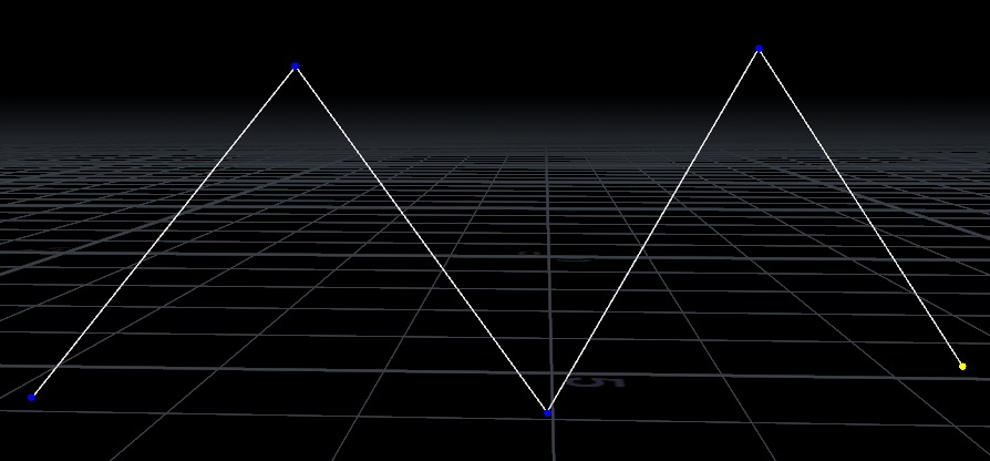
Polygon
Create a polyline.
NURBS Curve
Create a NURBS curve.
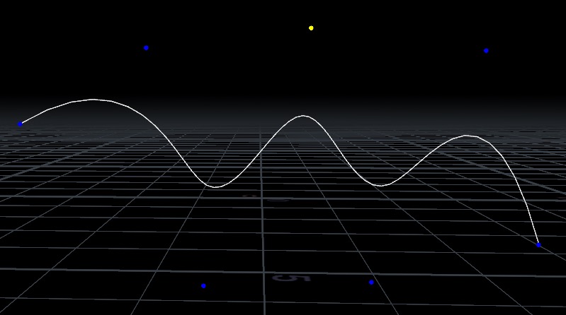
Bezier Curve
Create a Bézier curve.
Order
The order of the NURBS or Bézier curve. Higher order curves give more control vertices and smoother curve interpolation between on-curve knots. However, you should generally use the default order (4) unless you have a reason for needing higher-order curves. Note that changing the Order changes the interpretation of all existing curves to use the new order value.
The drawing mode is optimized for cubic Bézier curves (Order set to 4, the default). For higher-order Bézier curves, the drawing interface is the same as for cubic Bézier curves, but after you drag out the tangent handles, the node creates more than one tangent handle on the trailing side of the point. It creates the extra control points in line, so they have the same shape as a cubic Bézier would, but after you're finished drawing you can use the Edit mode to move the extra control points independently.
For NURBS, the drawing interface is always the same: placing points by clicking.
Reinterpret Curves as Current Type and Order
When on, all existing curves are converted by reinterpretting the curve points as the current Primitive Type and Order. When converting curves to NURBs or Bezier, the last point on the curve may be repeated to fully define the curve. When off, only newly created curves are given the current Primitive Type and Order.
Mode
The mode that the tool is currently in.
Select/Edit Mode
Modifies existing curves.
Draw Mode
Puts down new points.
Auto-Bezier Draw Mode
Put down new points when creating Bezier curves. Points are created as Auto Points. Tangents are optimized to create a bezier curve continuous in the first and second derivatives. Previous points are optimized until it either reaches back to the start of the curve, or a non-auto point.
Orient Mode
Create an orient attribute along curves by specifying target up vectors at specified anchor points.
Delete Selected Points
Removes the selected point(s), if any.
Join Selected Points
Joins two selected vertices together into a single vertex.
If the two selected vertices are on the same curve, the result is one closed curve. If the vertices are from different curves, the result is one curve instead of two.
Cut Curves at Selected Points
Cuts the curve at each selected point. After the cut, each selected point becomes an end point.
Any branches are also split prior to cutting curve vertices.
Add Segment Between Selected Endpoints
Joins the two selected vertices with a straight line.
If the two selected vertices are on the same curve, the result is one closed curve. If the vertices are from different curves, the result is one curve instead of two, with a segment added between the end vertices.
Delete Segments Between Selected Points
Removes any selected segments, possibly splitting curves around selected segments.
Fuse Branch
Fuse all selected points into a single branch point containing all the vertices from the selected points.
Split Branch
Split the selected branch points to create separate points for each vertex of the branched point.
Make Selected Points Corner
Turns an anchor point into a corner point.
Make Selected Points Smooth
Turns an anchor point into a smooth point, possibly snapping handles to be aligned.
Make Selected Points Balanced
Turns an anchor point into a balanced point, possibly snapping handles to be aligned.
Retract Tangents at Selected Points
Collapses the bezier handles down into a sharp bezier corner point.
Expand Tangents at Selected Points
Expands out the bezier handles to be intractable, if the selected point is collapsed.
Make Segments Between Selected Points Straight
Collapses the handles on the ends of the selected segments, converting the segment into a straight line.
Close Selected Curves
Closes all curves with at least one point selected.
Create Rounded Corners
Turns the selected corner points into rounded corners.
Remove Rounded Corners
Turns the selected rounded corners into ordinary corners.
Make Selected Points Auto
Makes selected points into auto points. Bezier curves are automatically computed to interpolate any auto points.
Make Selected Points Manual
Makes selected auto points into non-auto points and freezes the local interpolated curve so that it can be manually edited.
Reverse
Reverse selected curves.
Reset Operations
Resets all modeling operations that have been done. Resets the output geometry to the input geometry.
Snap Tangents when Fusing Ends in Draw Mode
Whether to snap the final tangent when fusing curves together or closing curves by clicking on the end point of another curve or the opposite end point of the same curve. Dragging out the tangent while fusing doesn’t snap the tangents.
Approximate Shape on Delete
Approximates the previous curve shape on a point delete.
Approximate End Tangents
Prioritizes keeping the end derivatives of a segment when approximating the previous curve shape on a point delete.
Soft Transform Radius
The soft transform radius when soft transforms are on.
Soft transforms are used when doing operations that manually move anchor points, including dragging points in edit and draw mode, dragging segments in polygons or NURBs curves, or bezier segments adjacent to rounded corners or auto points. This radius is relative to the distance along the backbone polygon of the given curve. For Polygons this is equivalent to the surface distance along the curve. For NURBS Curves this is equivalent to the distance along the control polygon of the curve. And for Bezier Curves, this is equivalent to the distance along the polygon that results from reinterpreting the curve as a polygon. In particular, in this polygon, auto points and rounded corners are collapsed to a single point, which can result in distances along the curve being slightly different than expected when looking at a curve.
Output 
Corner Points Group
The name of the group to create that contains the corner points. When chaining curve nodes, this can be used to ensure later curve nodes pick up the corner points from this node.
Smooth Points Group
The name of the group to create that contains the smooth points. When chaining curve nodes, this can be used to ensure later curve nodes pick up the smooth points from this node.
Auto Points Group
The name of the group to create that contains the auto points. When chaining curve nodes, this can be used to ensure later curve nodes pick up the auto points from this node.
Name
The name to place in the name attribute on all created geometry. Defaults to the name of the SOP ($OS).
X Axis
The name of the attribute to create to store the X Axis of the orientations created on points in the Orient Mode. When active, geometry showing the x axis is present in the viewport. The density and scale of guide gnomons showing the axes can be controlled in the state parameters.
Y Axis
The name of the attribute to create to store the Y Axis of the orientations created on points in the Orient Mode. When active, geometry showing the y axis is present in the viewport. The density and scale of guide gnomons showing the axes can be controlled in the state parameters.
Z Axis
The name of the attribute to create to store the Z Axis of the orientations created on points in the Orient Mode. When active, geometry showing the x axis is present in the viewport. The density and scale of guide gnomons showing the axes can be controlled in the state parameters.
Orient
The name of the orient attribute to create. The orient attribute created in the Orient Mode is stored in this attribute. When active, guide geometry showing the orient attribute is present in the viewport. In the state parameters, you can toggle drawing the orient guide geometry, as well as control the density and scale of guide gnomons.
Tangent Type
The method used to determine the implicit curve tangent. This tangent is used to parallel transport the orient attributes from the target points along the curves.
Align with Curve Tangent
When on, aligns orient attribute values with the curve tangent. When off, orient attribute values on target points are aligned with the value in Tangent.
Target Orientations
The target orientations specified on points along curves. When determining the orient attribute, these target orientations are placed on curves, and a parallel transport is used between target points to create an orient attribute that smoothly blends between target orientations. For any curves that do not have any target orientations, a default orient is placed on the first point of the curve, achieved by rotating the vector (0,0,1) onto the curve tangent.
Enable Target Orientation
Toggles this target orientation.
Point
The point to place the target orientation on.
Up
The target up vector. Target up vectors are made perpendicular to the curve tangent if Align with Curve Tangent is on, and are otherwise made perpendicular to the specified Tangent vector.
Tangent
The target tangent vector. When Align with Curve Tangent is off, this parameter is available to set alongside the Up vector, allowing you to fully specify the orientation of this target Point, without being constrained by the curve tangent.
Current Operation 
These parameters represent the transformations of the current operation. These are internally stored and cleared upon finishing actions, or starting new actions. Re-selecting points, finishing a movement of a component, or finishing an interaction with the transform handle all cause it to store the parameters and clear them.
Active Points
Points used in the current operation.
Translate
The amount to translate the selected points or the selected handle end point by.
Rotate
The amount to rotate (in degrees) the selected points with respect to the pivot.
Scale
The amount to scale the selected points with respect to the pivot.
Corner Points
A group parameter specifying the corner points. When chaining multiple curve nodes, this can be set with an input group, such as that created through Corner Points Group, to pick up the corner points from previous nodes.
Smooth Points
A group parameter specifying the smooth points. When chaining multiple curve nodes, this can be set with an input group, such as that created through Smooth Points Group, to pick up the smooth points from previous nodes.
Auto Points
A group parameter specifying the auto points. When chaining multiple curve nodes, this can be set with an input group, such as that created through Auto Points Group, to pick up the auto points from previous nodes.
Pivot Transform 
Pivot Translate
The position of the pivot, before any further translations.
Pivot Rotate
Specifies the axis to align the transform handle with. Upon finishing any operation with the transform handle, it snaps back to this rotation to begin a new edit. Is specified as three angles in degrees representing the amount to rotate around each axis.
Fixed Pivot
Whether to keep the pivot position the same when selecting new points. If off, the pivot resets to the center of the bounding box of the selected points on a selection change.
Rounded Corners 
View Rounded Corners
Whether to view rounded corners. When off, rounded corners are all shown with a radius of 0.0. The topology of created curves is not changed when this toggle is off.
Round Corner Points
A string parameter encoding the rounded corners and their radii.
Round Corner Radius
Sets the radius of the selected rounded corners.
Bake Selected Rounded Corners
Convert selected rounded corners into regular bezier segments.
Show Rounded Corner Widget
Whether to show a widget to modify rounded corner radii.
Show Rounded Corner Labels
Whether to show labels for the radii on the rounded corner widgets. These labels are off if Show Rounded Corner Widget is off.
Outputs 
curves
The set of curve primitives. Set its type with the Primitive Type parameter.
| See also |