-
Align
Transforms a layer to align with another layer.
-
Align Pixels
Shifts a layer to align pixelwise with another layer.
-
Attribute
Creates a detached attribute.
-
Attribute Extract
Extracts a detached attribute from a geometry.
-
Attribute Insert
Inserts a detached attribute into a geometry.
-
Attribute Sample with Adjacency
Creates a texture map of an attribute sampled from geometry.
-
Attribute from Layer
Extracts a detached attribute from a layer.
-
Auto Stereogram
Generates an image with a 3D illusion.
-
Bake Geometry Textures
Generates textures by baking between a low-resolution and high-resolution mesh at interactive speeds.
-
Bake Pre-Process
Sets up rays for baking, with a visualization state.
-
Bend
Curves images using handles or a captured region.
-
Blend
Blends two layers, VDBs, or attributes together.
-
Block Begin
Start of a block, containing its inputs.
-
Block End
End of a block, declaring its outputs.
-
Block to Geometry
Compiles a block and produces its geometry representation.
-
Blur
Applies a blur to a layer.
-
Bokeh
Creates a Bokeh effect by expanding each pixel by an aperture shape.
-
Bounding Rectangle
Finds the bounding rectangle of a mask.
-
Bright
Brightens a layer, VDB, or attribute.
-
Bubble Noise
Generates bubble noise.
-
Cable Filter
Removes empty wires from a cable.
-
Cable Merge
Combines two cables into one cable.
-
Cable Pack
Combines input layers into a cable.
-
Cable Rename
Renames a cable’s wires based on filters.
-
Cable Sort
Sorts a cable’s wires by name.
-
Cable Split
Splits a cable based on filtering parameters.
-
Cable Switch
Selects an input cable.
-
Cable Unpack
Extracts individual wires from a cable.
-
Cache
Caches the input layers for faster playback.
-
Camera
Creates a camera.
-
Camera Blend
Blends two cameras.
-
Camera Import
Creates a layer in a camera’s space.
-
Camera Properties
Adjusts the camera properties of a layer.
-
Cell Pattern
Generates cellular patterns.
-
Cellular Noise
Generates cellular noise.
-
Cellular Noise 3D
Generates cellular noise from 3D locations.
-
Channel Extract
Extracts a channel from a layer, VDB, or attribute.
-
Channel Join
Combines multiple Mono layers, VDBs, or attributes into one multichannel output.
-
Channel Split
Divides the input’s channels into Mono layers, VDBs, or attributes.
-
Channel Swap
Swaps channels within a multichannel layer, VDB, or attribute.
-
Checkerboard
Creates an alternating checker pattern.
-
Chladni Cymatic Patterns
Generates interference patterns that represent various vibration modes.
-
Chroma Key
Keys an input based on hue, saturation, and luminance ranges.
-
Chromatic Aberration
Adds chromatic aberration to your image.
-
Clamp
Clamps an input layer, VDB, or attribute.
-
Cloud Noise 3D
Generates a billowy cloud noise.
-
Color Correct
Adjusts colors in the image.
-
Combine Normals
Blends two normal maps together.
-
Compare
Creates a mask by comparing two layers, VDBs, or attributes.
-
Compare and Blend
Compares two pixel values on a layer, VDB, or attribute and outputs either a true or false input for that pixel.
-
Configure Stamps
Creates stamp/sprite attributes on points with randomization controls and inputs.
-
Constant
Initializes pixels to constant values.
-
Contact Sheet
Arranges input layers into a contact sheet.
-
Contrast
Applies contrast to a layer, VDB, or attribute.
-
Convert Depth
Converts depth layers between height, depth, and distance.
-
Convert Normal
Converts normal layers between signed and offset.
-
Convolve 3×3
Convolves a layer by a 3×3 kernel.
-
Convolve Filter
Convolves an image with an arbitrary kernel image using an FFT.
-
Copy and Transform
Copies stamps and applies transformations to the copies.
-
Corner Detect
Detects corners in an input layer.
-
Corner Pin
Pins a layer’s corners in a reference layer.
-
Crop
Crops a layer to a new size.
-
Cross Product
Performs a cross product of two RGB layers, VDBs, or attributes.
-
Cryptomatte
Builds a matte from cryptomatte layers.
-
Cryptomatte Decode
Decodes a cyrptomatte into coverage and ID.
-
Cryptomatte Encode
Encodes a coverage and object hash into a cryptomatte layer.
-
Crystal Noise
Generates a sharp and angular Worley noise type.
-
Crystal Noise 3D
Generates a sharp and angular Worley noise type from 3D locations.
-
Curl
Computes the curl of a vector field.
-
Curl Noise
Generate curl noise.
-
Curl Noise 3D
Generates 3D curl noise.
-
Curvature
Computes the curvature of a layer.
-
Curve 3D
Lets you interactively draw Bézier curves using tools similar to 2D illustration programs, as well as polylines and NURBS.
-
Curve Animate 3D
Lets you interactively draw and animate Bézier curves using tools similar to 2D illustration programs, as well as polylines and NURBS.
-
Defocus
Defocuses an input layer.
-
Denoise AI
Denoises an input layer.
-
Denoise TVD
Removes white noise from an image.
-
Derivative
Computes the derivative of the source layer along its width (x-axis) and height (y-axis).
-
Despill
Removes color spill from an input layer.
-
Dilate Erode
Dilates or erodes a layer.
-
Distort
Distorts an input layer.
-
Distort with Adjacency
Distorts a layer over texture seams using adjacency.
-
Dot Product
Performs dot product between two layers.
-
Drop Shadow
Composites a copy of a layer under the original to create a shadow.
-
Edge Detect
Detects edges in the input image.
-
Edge Detect by Contour
Detects varying-width silhouette lines.
-
Edge Detect by Depth
Detects varying-width self-occluding silhouettes.
-
Edge Detect by Normal
Detects varying-width crease-lines.
-
Eikonal
Computes distances by solving the Eikonal equation.
-
Equalize
Equalizes colors by stretching or shifting their range.
-
Error
Generates a message, warning, or error.
-
Extrapolate Boundaries
Fills empty areas of an image using colors at the edges of non-empty areas.
-
Extrapolate with Adjacency
Fills areas of a texture outside the UV islands with information from their island neighbors.
-
Fast Fourier Transform
Computes the Fourier transform of an image.
-
Feather
Smooths out sharp changes in contrast.
-
Fetch
Brings a COP node’s outputs into the current network.
-
File
Loads an image or video from disk.
-
Fill
Fills a layer with a constant value.
-
Fill Connected
Flood fills the connected regions of a layer.
-
Filter Frequencies
Boosts or suppresses spatial frequencies in an image.
-
Flip
Flips a layer horizontally, vertically, or diagonally.
-
Flow Block Begin
Start of a Flow simulation block.
-
Flow Block End
End of a Flow simulation block.
-
Flow Project Non-Divergent Multigrid
Removes divergent components from a 2-dimensional vector field.
-
Font
Rasterizes text onto a layer from Type 1, TrueType, and OpenType fonts.
-
Fractal Noise
Generates fractal noise.
-
Fractal Noise 3D
Generates fractal noise from 3D locations.
-
Fractal Sample
Generates a fractal of the source input that you can randomize.
-
Function
Applies a mathematical function to a layer.
-
Gamma
Applies gamma correction to a layer, VDB, or attribute.
-
Geometry Attribute from Layer
Samples layers with a geometry’s attribute to create attributes from those layers.
-
Geometry to Adjacency
Rasterizes geometry to generate an adjacency cable.
-
Geometry to Layer
Converts a volume, VDB, or camera primitive into a layer or VDB.
-
Glow
Adds glow to an image based on its luminance.
-
Grunge Aurora
Generates a pattern resembling an aurora display.
-
Grunge Bark Strips
Generates a pattern resembling bark strips.
-
Grunge Birch Bark
Generates a pattern resembling the bark of a birch tree.
-
Grunge Drips
Generates a pattern resembling drips.
-
Grunge Galvanized Steel
Generates a pattern resembling galvanized steel.
-
Grunge Layered Noise
Generates a higher-level noise pattern by layering simple noises.
-
Grunge Leaking Streaks
Generates a pattern resembling leaking streaks.
-
Grunge Moisture
Generates a pattern resembling sponge-like moisture.
-
Grunge Mold Spots
Generates a pattern resembling mold spots.
-
Grunge Pine Bark
Generates a pattern resembling the bark of a pine tree.
-
Grunge Rust
Generates a pattern resembling rust on a surface.
-
Grunge Rusty Surface
Generates a pattern resembling a rusty surface.
-
Grunge Sheets
Generates a pattern resembling sheets.
-
Grunge Wipe Trails
Generates a pattern resembling circular wipe trails.
-
HSV Adjust
Converts between RGB and HSV color spaces, or modifies HSV.
-
Heat Distort
Distorts the input layer to simulate heat around fire and other mirage effects.
-
Heat Distort by Layer
Distorts the input layer using another layer to simulate heat around fire and other mirage effects.
-
Height to Ambient Occlusion
Imagines a sphere for each pixel and determines how occluded that sphere is based on its surroundings.
-
Height to Caustics
Creates caustic patterns on the ground from a refractive height layer.
-
Height to Normal
Converts a height layer to a normal layer.
-
Height to Shadow
Creates shadows using a virtual light source.
-
HeightField Clip
Clamps height values to a minimum and/or maximum value.
-
HeightField Erode
Simulates hydraulic and thermal erosion at a specific scale to create more realistic terrain.
-
HeightField Mask by Feature
Creates a mask based on different features of the heightfield.
-
HeightField Project
Projects 3D geometry onto a heightfield.
-
HeightField Slump
Simulates loose material sliding down inclines and piling at the bottom.
-
HeightField Strata
Adds sedimentary layering patterns to a HeightField.
-
HeightField Terrace
Creates stepped plains from the slopes of a HeightField.
-
HeightField Transform 2D
Transforms a height layer in 2D.
-
HeightField Transform 3D
Transforms a height layer in 3D.
-
HeightField Visualize
Visualizes layers as a colored heightfield by converting them into geometry
-
HeightField to Mono
Converts a heightfield into a grayscale mono layer.
-
Hex Tile
Randomly tiles texture.
-
Histogram
Builds a histogram from a layer.
-
Hyperbolic Tile
Generates hyperbolic polygon tiles for texture patterns.
-
ID to Mask
Creates a mask from an ID layer based on filtering parameters.
-
ID to Mono
Converts an ID layer, VDB, or attribute into a float.
-
ID to RGB
Converts an ID layer, VDB, or attribute into an RGB layer, VDB, or attribute.
-
ID to SDF
Computes a signed distance field from changes in ID values.
-
Illegal Pixel
Detects and then fixes or highlights illegal pixels in images.
-
Input
Fetches the input to a subnetwork.
-
Integrate Volume
Integrates a VDB along camera rays.
-
Invert
Inverts a layer, VDB, or attribute.
-
Invoke Block
Runs a block using inputs plugged into this node.
-
Invoke Geometry
Runs a program saved into geometry using inputs plugged into this node.
-
Julia Fractal
Computes the Julia set to create a fractal.
-
Knit
Generates a grid of knitted fabric stitches.
-
Kuwahara Filter
Applies the Kuwahara filter, which creates painterly effects.
-
Labs UV Grid Texture
Generates procedural UV grid textures.
-
Laplacian
Computes the Laplacian of the source layer.
-
Lattice Deform
Applies grid-based deformation to a layer.
-
Layer
Generates a layer.
-
Layer Merge
Combines all inputs.
-
Layer Properties
Edits basic layer metadata.
-
Layer Property Copy
Transfers layer properties from one layer, VDB, or attribute to another.
-
Layer Property Create
Adds or edits user-defined properties on a layer.
-
Layer Property Delete
Removes user-defined properties from a layer.
-
Layer from Attribute
Fills a layer from a detached attribute.
-
Layer from Curves
Render Curves into a Layer.
-
Layer from VDB
Sets a layer’s values from a VDB.
-
Layer to Geometry
Converts a layer or VDB into geometry.
-
Layer to Points
Creates points based on a layer.
-
Layer to VDB Leaf Points
Creates a point for each leaf of a VDB that would be in an envelope.
-
Lens Distort
Adds radial and tangential distortion to a layer based on OpenCV coefficients.
-
Light
Lights a layer given a light direction and normals.
-
Live Video
Captures images from a live video source.
-
Logic
Applies logic operations to ID layers.
-
ML Computer Vision Inference
Apply a model trained using the ML Train Computer Vision TOP.
-
Mask Combine
Combines several mask layers from an input cable into a single mask.
-
Mask from Curves
Creates a mask from 2D curves.
-
Match Camera
Transforms a layer to match a reference camera.
-
Match UDIM
Reframes pixels of a layer to match a particular UDIM tile.
-
Median
Applies a median filter to an image.
-
Mirror
Mirrors an image based on an arbitrary number of planes.
-
Mono
Converts a layer, VDB, or attribute into a mono, VDB, or attribute.
-
Mono to HeightField
Converts a mono layer into a heightfield.
-
Mono to ID
Converts a mono layer, VDB, or attribute into an integer.
-
Mono to RGB
Converts a mono layer, VDB, or attribute into an RGB layer, VDB, or attribute.
-
Mono to RGBA
Converts a mono layer into an RGBA layer.
-
Mono to SDF
Computes a signed distance field from an iso-level of a mono layer.
-
Neural Cellular Automata Core
Runs a neural cellular automata model to evolve cell states.
-
Neural Cellular Automata Decode
Decodes a cell state from the Neural Cellular Automata Core into a visible pattern.
-
Neural Layer to Depth (MoGe-2)
Estimates metric-scale depth, normal, and position maps from an input image.
-
Neural Layer to Mask (SAM2)
Creates a mask based on coordinates set through prompts.
-
Normal to Height
Reconstructs a height layer from a normal layer.
-
Null
Passes inputs to the outputs.
-
OCIO Transform
Converts color spaces using OCIO transforms.
-
ONNX Inference
Applies inference from an ONNX Machine Learning model.
-
Ocean Evaluate
Converts the layers of an ocean spectrum into an animated ocean surface.
-
Ocean Spectrum
Generates layers containing information for simulating ocean waves.
-
OpenCL
Executes an OpenCL kernel on layers, attributes, volumes, and VDBs.
-
Output
Collects the outputs of a subnetwork.
-
Paint 3D
Paint on a COP layer or UV-mapped geometry.
-
Phasor Noise
Generates phasor noise, which resembles a wave pattern.
-
Pixelate
Increases the size of pixels to pixelate an input layer.
-
Planar Inflate
Inflates a 2D SDF into a height layer.
-
Point Delete
Deletes points from a point cloud geometry.
-
Point Generate
Adds points to a point cloud geometry.
-
Point Merge
Merges point cloud geometries.
-
Points from Blobs
Creates points from blobs in an input layer.
-
Polar to UV
Converts polar coordinate pixels to Cartesian pixels.
-
Position Map
Generates a position map.
-
Position Sample
Samples an input texture by position.
-
Prefix Sum
Computes the prefix sum of a layer.
-
Premultiply
Premultiplies or un-premultiplies an RGBA layer.
-
Preview Material
Applies the preview material to geometry.
-
Project on Layer
Projects a layer onto a target layer.
-
Pyro Activate
Changes the activation of VDBs in a Pyro simulation.
-
Pyro Advect
Advects VDBs by Velocity.
-
Pyro Advect by Map
Advects a VDB by a flow map.
-
Pyro Axis Force
Applies a force around an axis to a velocity VDB.
-
Pyro Block Begin
Start of a Pyro simulation block.
-
Pyro Block End
End of a Pyro simulation block.
-
Pyro Build Advection Map
Constructs a flow map from a velocity VDB.
-
Pyro Buoyancy Force
Applies a Buoyancy force.
-
Pyro Collision Shape
Creates points representing implicit surfaces to add collision objects into a Pyro simulation.
-
Pyro Collision from Shape
Adds collision from pyro collision points representing implicit surfaces, into a VDB.
-
Pyro Configure
Configures a Pyro simulation.
-
Pyro Dissipate
Dissipates a VDB’s values over time.
-
Pyro Disturbance
Applies disturbance to a velocity VDB to break up still air.
-
Pyro Emit from Flame
Burns up the flame field.
-
Pyro Light Ambient
Builds a light field of ambient illumination of a VDB.
-
Pyro Light Scatter
Builds a light field of internal glow of a VDB.
-
Pyro Light from Points
Builds a light field of points lighting a VDB.
-
Pyro Packed MipMap
Builds an in-place MipMap of a VDB.
-
Pyro Project Non-Divergent Electro Static
Removes divergence from a velocity VDB.
-
Pyro Source Shape
Creates points representing implicit surfaces to source into a Pyro simulation.
-
Pyro Source from Layer
Sources from a layer’s envelope into a VDB.
-
Pyro Source from Points
Sources points into a VDB.
-
Pyro Source from Shape
Sources from pyro source points representing implicit surfaces, into a VDB.
-
Pyro Source from Volume
Sources from a VDB into another VDB.
-
Pyro Turbulence
Apply turbulence to a velocity VDB.
-
Pyro Uniform Force
Applies a uniform force.
-
Pyro Velocity Scale Force
Scales fluid velocity based on the fluid’s current speed.
-
Pyro Vortex Confinement Force
Applies a vortex confinement force to a velocity field.
-
Python Snippet
Runs a snippet of Python on layers.
-
Quantize
Quantizes input data into discrete steps.
-
RGB to RGBA
Converts RGB layers or attributes to RGBA.
-
RGB to UV
Splits an RGB layer or attribute into UV and mono layers or attributes.
-
RGBA to RGB
Converts RGBA layers or attributes to RGB.
-
RGBA to UV
Splits an RGBA layer or attribute into two UV layers or attributes.
-
ROP Image
Writes the output of a COP network to disk.
-
Ramp
Generates linear and radial ramps.
-
Random Mono
Creates a mono layer, VDB, or attribute with random values.
-
Random RGB
Creates an RGB layer, VDB, or attribute with random colors.
-
Rasterize Curves
Rasterizes curves onto a layer.
-
Rasterize GSplats
Rasterizes Gaussian Splats onto layers.
-
Rasterize Geometry
Rasterizes geometry onto a layer.
-
Rasterize Implicit Surface
Rasterizes an implicit surface onto a layer.
-
Rasterize Layer
Rasterizes a layer onto another layer’s camera.
-
Rasterize Setup
Prepares geometry for the Rasterize Geometry COP.
-
Rasterize Volume
Renders a volume viewed through a camera.
-
Ray Trace
Performs ray tracing on an input mesh based on an origins and directions map.
-
Reaction-Diffusion Block Begin
Start of a Reaction-Diffusion simulation block.
-
Reaction-Diffusion Block End
Creates unique patterns by solving the reaction and diffusion of multiple chemicals as described by its inputs and parameters.
-
Refract from Height
Refracts an image through a height layer.
-
Remap
Remaps a layer, VDB, or attribute.
-
Resample
Performs image scaling by changing the width, height, and pixel sizes.
-
Ripple Block Begin
Start of a Ripple simulation block.
-
Ripple Block End
End of a Ripple simulation block
-
SDF Adjust
Modifies the values for a Mono SDF layer.
-
SDF Blend
Combines two Mono SDF layers.
-
SDF Shape
Builds a 2D signed distance field of a selected shape.
-
SDF to Mono
Converts an SDF field to a mono image layer.
-
SDF to RGB
Converts an SDF field to an RGB color layer.
-
SOP Import
Imports SOP geometry into Copernicus.
-
SOP Invoke
Invokes a compiled SOP block on the inputs.
-
SOP Invoke Graph
Invokes a geometry SOP graph on the inputs.
-
Scatter Shapes
Scatters input stamps across the image using randomization controls.
-
Scatter on Curves
Scatters input stamps along an input curve using randomization controls.
-
Segment by Connectivity
Segment a layer into connected components.
-
Segment by Value
Segment a mono layer into bands of similar value.
-
Sequence
Sequences parts of one or more inputs temporally.
-
Sequence Blend
Blends multiple layers together.
-
Sharpen
Sharpens an input layer to increase the definition of its edges.
-
Slap Comp Import
Import live layers from the Solaris Viewport.
-
Slope Direction
Converts a height layer into a direction layer.
-
Smooth Fill
Smoothly fills a region of a layer.
-
Solve Poisson
Solves Poisson’s equation inside a 2D boundary.
-
Solve Poisson Multigrid
Solves Poisson’s equation in a rectangular region using geometric multigrid.
-
Space Transform
Transforms positions and UV values between spaces.
-
Space Transform with Adjacency
Transforms a vector from world space into tangent space.
-
Sphere Sample
Samples a layer onto a sphere.
-
Stamp Points
Stamps layers from point positions.
-
Star Glow
Streaks the layer multiple times in different directions to create a star effect.
-
Stash
Stashes the input of the node on command and uses it as the node’s output.
-
Statistics
Outputs the average, minimum and maximum values of the input layer
-
Statistics by ID
Compute statistics for each ID island.
-
Streak Blur
Streaks an image, adding a motion blur effect.
-
Subnetwork
Used to organize a collection of COPs into one node.
-
Surface Dither
Applies a halftone dithering pattern relative to UVs.
-
Swirl
Twists an image layer into a spiral shape.
-
Switch
Selects an input layer.
-
Switch If Wired
Selects an input based on what is connected.
-
Switch by Type
Selects an output layer by the type of the inputs.
-
Test Geometry: Capybara
Creates a capybara, which can be used as test geometry.
-
Test Geometry: Otto
Creates Otto, a production quality test character.
-
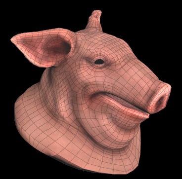
Test Geometry: Pig Head
Creates a pig head, which can be used as test geometry.
-
Test Geometry: Rubber Toy
Creates a rubber toy, which can be used as test geometry.
-
Test Geometry: Shader Ball
Creates a shader ball, which can be used to test shaders.
-
Test Geometry: Squab
Creates a squab, which can be used as test geometry.
-
Test Geometry: Tommy
Creates a soldier, which can be used as test geometry.
-
Tile Pattern
Generates rectangular tiles for texture patterns.
-
Time Blend
Blends intraframe values for layers and VDBs.
-
Time Loop
Repeats input frame range to form a looping animation.
-
Time Pack
Combines its input at multiple times into a cable.
-
Time Shift
Cooks its input at a different time.
-
Tone Map
Applies a filmic tone mapping curve to compress a high dynamic range input into a displayable range.
-
Transform 2D
Transforms a layer in 2D.
-
Transform 3D
Transforms a layer in 3D.
-
Triplanar
Generates a texture by projecting X, Y, and Z textures onto the position layer.
-
Triplanar Hex Tile
Seamless texturing and normal mapping of triplanar projections without visible repetitions.
-
Triplanar UV
Generates UVs in three orthogonal projections.
-
Turing Patterns
Applies a filter to create Turing patterns.
-
Two Way Switch If Wired
Selects between two inputs based on if you wire in another input.
-
UDIM Pack
Combines its input at multiple UDIMs into a cable.
-
USD Material
Represents a USD material referenced from disk.
-
UV Inverse
Computes the inverse of a UV distortion map.
-
UV Map
Generates a UV Map.
-
UV Map by ID
Creates a UV Map for each connected ID island.
-
UV Sample
Samples an input layer using a UV layer or attribute.
-
UV Shape
Generates UV coordinates for common 2D shapes.
-
UV Transform
Transforms the values of a UV layer in 2d space.
-
UV to Polar
Converts Cartesian coordinate pixels to polar coordinate pixels.
-
UV to RGB
Combines a UV and mono layer or two attributes to create an RGB layer or attribute.
-
UV to RGBA
Joins two UV layers or attributes into an RGBA layer or attribute.
-
VDB Activate from Points
Activates leaves on a VDB according to a point cloud.
-
VDB Leaf Points
Creates a point for each active leaf in a VDB.
-
VDB Position Map
Stores in each voxel that voxel’s position.
-
VDB Reshape
Rebuilds a VDB to match another VDB’s topology.
-
VDB Visualize
Creates multi-volume visualization.
-
VDB Visualize Slice
Extracts a slice from a VDB as Geometry for visualization.
-
VDB Visualize Tree
Builds a geometry visualizing the topology of a VDB.
-
VDB Visualize Velocity
Traces streamers through a velocity VDB.
-
VDB from Layer
Sets VDB values from the closest values in a layer.
-
Vector Transform
Transforms values of an RGB layer, attribute, or Vector VDB in 3D space.
-
Vector Transform 2D
Transforms the values of a UV layer or attribute in 2D space.
-
Vignette
Darkens the corners of an input layer.
-
Visualize Velocity
Creates an RGBA Layer visualizing a 2d velocity field.
-
Weave
Generates a woven fabric pattern of interlacing fibers.
-
Wipe
Performs a wipe transition between two images.
-
Worley Noise
Generates Worley noise.
-
Worley Noise 3D
Generates Worley noise from 3D locations.
-
Wrangle
Runs a VEX snippet to modify layer values.
-
Z Composite
Composites two layers by depth.