| On this page | |
| Since | 22.0 |

Wire in either a COP layer or a geometry with a uv attribute to paint on. The canvas input layer serves as the background image on which paint is applied. If both uvgeo and canvas are wired in, canvas is still used as the background layer, but uvgeo provides the surface on which to visualize the painted texture and project brush strokes.
Work with this COP is typically done through its two GUI components: its panel and its viewer state. These components allow you to manipulate the higher-level objects this COP conceptually stores and processes: PaintLayers, the blend stack, brushes, and alphas.
Concepts 
PaintLayers 
A PaintLayer has a color image, an alpha image, and optionally a mask image. It is essentially a bundle of COP layers treated as a single layer. PaintLayers are stored and output by the node as 3 distinct COP layers, all with the same resolution and COP layer properties (same resolution, same display and data window). The color layer can have 1, 2, or 3 channels, referred to by their COP type names: Mono, UV, and RGB. In a sense, these are your “data” channels, because these channels aren’t given a particular meaning by this COP, aside from how you choose to blend them with other PaintLayers. Typically, the color layer stores actual color. The alpha and mask layer are both single-channel (Mono) COP layers.
All the node’s PaintLayers are returned by the layers node output, which is a COP cable. Since a COP cable stores COP wires and PaintLayers are a higher-level abstraction over COP layers, you see the individual underlying constituent COP layers in this cable as separate cable wires. The names of these wires stored in the cable are derived from the name of the PaintLayer, as stored in the blend stack: a layer named foo in the blend stack appears in the layers output cable as foo.color, foo.alpha, and an optional foo.mask entry. You may want to use  Cable Unpack to extract individual wires from this cable.
Add PaintLayers by pressing the layer icon underneath the blend stack. To delete a range of layers in the blend stack, select the range and click Delete, or Delete All to delete all the PaintLayers in the blend stack. This brings the node back to its default state of outputting the canvas input with nothing blended onto it. You can also duplicate a range of layers by selecting it in the blend stack,  and choosing Duplicate Selected.
PaintLayers are identified by their names so these must be unique. If you attempt to rename a PaintLayer to have the same name as another existing PaintLayer, they are disambiguated by a #<integer> discrimination suffix automatically appended to the name of the PaintLayer being renamed.
Note
Color and alpha are stored as separate COP layers, but color is stored premultiplied by the associated alpha layer. This is because premultiplied representation is used internally to evaluate the blend stack, combined with the fact that while it’s possible to create 1- and 2-channel color layers, there are no COP layer types that semantically represent Mono+Alpha or UV+Alpha, that would be interpreted correctly by nodes like  Blend.
Note
A PaintLayer is simply these 3 COP layers. There is currently no support for painting geometries with multiple UV tiles (UDIMs). To work with such geometries, you may wish to split the geometry by UV tile, shift the UV coordinates into the 0-to-1 range, and use a separate Paint 3D node to paint textures for each UV tile.
Blend Stack 
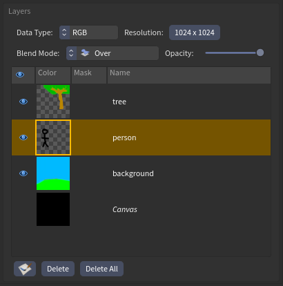
Displayed by the bottom-left widget in the panel, the blend stack is a description of how to blend together all the stored PaintLayers, along with the input canvas. It is a list of PaintLayers. In the blend stack widget, this list is visually ordered from bottom to top; lower layers come before higher layers. The canvas layer is displayed at the bottom of this list widget, although this visual entry is not a PaintLayer because it represents the live input to the node. The canvas does correspond to entries in the layers output, because it is not stored on the node. Each PaintLayer entry in the blend stack, along with its image contents, also defines a blend mode and an opacity. This describes how to blend it onto the accumulation of layers that come before it (below it).
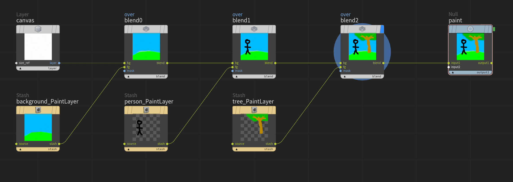
Conceptually, this list of PaintLayers translates into a sequence of blend operations, that is, a chain of Blend COP nodes. Each Blend in the chain corresponds to a PaintLayer in the stack, and is invoked with:
-
modeparameter: The blend mode of the corresponding PaintLayer entry in the blend stack -
maskparameter: The opacity of the corresponding PaintLayer entry in the blend stack -
bginput: The result of the previous Blend node in the chain -
fginput: The current PaintLayer’s color and alpha, combined -
maskinput: The current PaintLayer’s mask, if it has one (otherwise unwired)
For the initial Blend in the chain, the canvas input is used as the bg. If no canvas is wired, a default canvas is constructed using the COP network context settings. For the final Blend in the chain, the output is used as the paint output of this COP.
Note
Blend stack evaluation is the non-interactive function of this COP. When you are not interacting with the node through its viewer state or panel, the behavior of this node is essentially equivalent to the Blend chain described above.
Note
Regardless of the signature chosen for this node and regardless of the datatypes of the color images of the stored PaintLayers, the intermediate datatype passed through this conceptual chain of blend nodes is RGBA. After the chain is evaluated, if the node’s signature is Mono, UV, or RGB, the color is divided by the alpha to disassociate it. When the node’s signature is RGBA or Metadata, in both cases the output type is RGBA, so the result of the conceptual blend chain is output directly. As a consequence, the final alpha channel is always computed, but is only output for these two signatures.
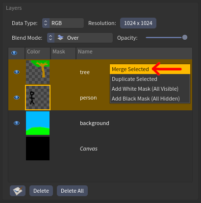
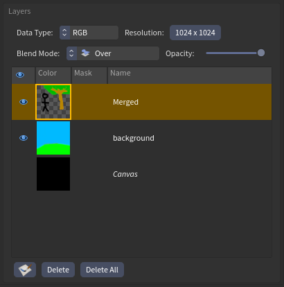
It may sometimes be useful to collapse a range of layers in the blend stack into a single layer. To do this, select the range, and choose Merge Selected. This replaces the range with a single layer named “Merged”, with a blend mode of Over. The way this merged layer is produced is identical to how the node evaluates the entire blend stack, except only the selected range of PaintLayers is used to produce the conceptual Blend chain, and instead of the canvas layer being used as the initial value in the chain, a transparent color=(0,0,0), alpha=0 canvas is used instead. The properties of this ephemeral canvas are taken from the initial (bottom) layer being merged.
Brushes and Alphas 
Three of the node’s viewer state tools are brushes: the Paint, Erase, and Smooth tools. Brush settings can be modified through the parameter dialog, while previewing their look using the brush and alpha preview images.
Pressing the Save Brush as Recipe or Save Alpha as Recipe button in the parameter dialog causes a “Save Brush” or “Save Alpha” dialog to open, allowing you to save the brush or alpha used by the current tool as a partial node preset recipe. An alpha recipe is a subset of a brush recipe, meaning brush recipes also contain all the parameters describing a brush’s alpha.
To load a saved recipe, click on either the brush or alpha preview image.
An alpha may be procedural (a circle or square with falloff) or a raster image. When painting with a procedural alpha, the alpha is sampled with infinite precision, and so the precision of the brush is only limited by the resolution of the writing layer. A raster image may be used as the alpha by loading it from a file path. When a brush or alpha recipe referencing such a raster image file is saved, the raster is embedded as a PNG inside the generated recipe HDA.
Note
The performance of brushes may be impacted by using an alpha with too high of a resolution.
Note
While the brush and alpha recipes generated by this button are partial node preset recipes, it is not possible to edit the parameters stored by these recipes through the recipe manager. This is because, in order for the same recipe to be applicable to all 3 brush tools (Paint, Erase, and Smooth), the recipes make use of recipe prescripts to dynamically populate the correct parameters upon application. This allows you to save a recipe for the Paint brush and load it into the Erase brush. Thus the intended workflow for modifying these recipes is loading them into an instance of Paint 3D, changing some parameters, and re-saving the recipe.
GUI 
Panel 
The panel allows you to modify the metadata of PaintLayers, the blend stack, and the settings of the viewerstate tools. It is split into three main sections:
-
In the top left: Visualizations of the current brush alpha and brush preview.
-
In the bottom left: The blend stack widget.
-
On the right: The node’s parameter dialog.
Brush and Alpha Preview 

These images show you what the current brush for the current tool looks like if you start painting. When the Sample or Fill tools are selected, because these tools are not brushes, the Paint tool’s preview is shown instead.
Clicking on either of these images opens a catalog window of all the saved recipes of the corresponding type. Picking a recipe from the catalog sets the relevant parameters on the node: picking a brush recipe sets all the parameters for the current brush tool, and picking an alpha recipe sets only the alpha parameters for the current brush.

Parameter dialog 
All of the non-internal node parameters are shown here. This is a native parameter dialog widget, the same kind you can see normally by clicking the Show/Hide Parameters button in the toolbar of a Node Parameters pane. All of the parameters here control interactive behavior of the node. None of them affect the two node outputs that are meant to be used downstream: paint and layers. The only parameters that affect the paint and layers outputs are the blendtree and layers internal data parameters, which are typically manipulated through the blend stack widget.
See also: Parameters.
Viewer State 
The viewer state lets you edit the contents of PaintLayers, and is therefore how you actually paint. It has five tools and exactly one of these is active at any time. Three of these tools are brushes (Paint, Erase, and Smooth), and two are discrete operations (Sample and Fill). Tools are used with a  drag (or drawing tablet pen stroke), or in the case of Fill, just a click. The current tool is indicated in the top row of the HUD. With the default keybinds, the current tool can be changed in the viewer state with 1, 2, 3, 4, 5. It’s also possible to use the radial menu to change the current tool.
Note
Which tool is active is stored as the value of the tool parm tuple, which is actually a virtual parameter representing the currently open tab of the Tools parameter folder, in the parameter dialog. Because of this, it’s possible to switch tools by opening the desired tool’s tab, and the currently open tool tab always reflects what tool is currently active.
In addition to a current tool, a PaintLayer must also be selected for modification in order to paint. If the canvas is not selected in the blend stack widget, a PaintLayer is. This PaintLayer is called “the writing layer”, since any viewer state tool that modifies a layer only affects this one.
Finally, with a PaintLayer selected, you are either writing to its color and alpha, or its mask. This is determined by the Write to Mask parameter, and can be changed by clicking on the corresponding thumbnail in the blend stack. Clicking on the color thumbnail causes the color and alpha to be selected for writing, and clicking on the mask thumbnail causes the mask to be selected.
Brush Tools 
There are three brush tools: Paint, Erase, and Smooth. In addition to changing between these tools with 1, 2, 3, the radial menu, or clicking open the corresponding tool tab in the parameter dialog, you can also temporarily switch to a different tool by holding down either ⇧ Shift to temporarily switch to the Smooth tool or ⌃ Ctrl to temporarily switch to the Erase tool. Temporarily switching tools uses all the parameters from that respective temporary tool.
For all three brush tools, strokes are divided into “stamps”. The placement of these stamps is handled exactly the same between the three brush tools: mouse events are processed by the viewer state and spaced out into evenly spaced “stamp transforms” according to the brush’s parameters (which can be saved and loaded as recipes). These tools only differ in what operation is applied for each stamp. Given a stamp transform,
-
the Paint tool adds more paint using the foreground color to the region. This increases the alpha value.
-
the Erase tool subtracts paint from the region, by decreasing the alpha.
-
the Smooth tool, for every stamp transform, uses the transform to rasterize the UV attribute of the given geometry, samples the writing layer mapped to the geometry at those UVs, blurs the resulting snapshot, and projects it back onto the writing layer. This is a significantly more expensive operation.
Note
Each stamp transform is a description of how to apply a brush stamp. It describes the local coordinate system of the stamp with respect to the world. The transformation between world-space and this local coordinate system is projective, and so can be orthographic or perspective.
-
When using Surface stroke alignment, the tangent plane and normal vector of the surface under the mouse is used to construct an orthographic stamp transform.
-
When using Screen stroke alignment, the projection of each stamp transform is derived from the viewport NDC-to-world transform, and so the projection type matches that of the viewport.
All three brush tools position their alpha image according to each stamp’s local coordinate system, to determine how the effect of the stamp varies across the paintable surface.
Sample Tool 
This tool replaces the current foreground color with the color of the texture under the mouse. Either the writing layer or the blend result can be sampled, and which is used is determined by the Sample All Visible Layers parameter. When writing to a mask, the mask value is sampled instead and stored as the new foreground mask color.
Fill Tool 
This tool floodfills a region of the writing layer with the foreground color. The region filled depends on the location pressed, the value of the color image at that location (or the mask image, if writing to a mask), and the fill threshold. Essentially, the floodfilled area extends as long as the currently traversed color is close enough to the color that was originally clicked.
Parameters 
Signature
The canvas type. For a metadata or RGBA signature the type of the paint output is RGBA. For a metadata canvas, RGBA (0,0,0,0) is used as the canvas color. Otherwise, for the Mono, UV, and RGB signatures the type of the paint output is the same as that of the canvas input, and 1 is used as the input alpha value.
Group
A group expression selecting surface primitives to paint on. Only this region of uvgeo is paintable, as texels outside this group remain unmodified.
Hide Rest
Shows only the region of uvgeo in the specified group. When off, visualize the entire uvgeo, regardless of what “Group” is set to.
FG Color
The color currently used for writing to a PaintLayer’s color.
BG Color
An extra color that can be swapped with the foreground color in the viewer state. Swapping is bound to X by default in the viewer state.
FG Mask
The value currently used for writing to a PaintLayer’s mask.
BG Mask
An extra value that can be swapped with the foreground mask value in the viewer state. Swapping is bound to X by default in the viewer state.
Preferences 
2D Paint Mode
Whether to ignore the input geometry for visualization purposes. This is a way to switch from painting directly on the input 3D geometry to the 2D texturemap. By default, it’s bound to F in the viewer state.
Stroke Alignment
How the stroke is positioned and oriented in 3D space while painting. Surface: A ray is repeatedly cast from the mouse position to the input geometry. Where it hits, a local coordinate system is constructed for each stamp, with the surface normal as Z, either the stroke direction or tangent vector most closely directed toward Up Direction as Y, and the cross product of these as X. Each stamp can thus be thought of as a rectangular prism centred on this local coordinate system, whose depth (along the Z axis) is determined by the Depth Falloff.
Screen: Stamps are positioned along the screen-space stroke. For each stamp, a local coordinate system is constructed, with either the stroke direction or screenspace “up” as Y, the screen-space orthogonal direction as X, and the direction from the viewport camera toward the mouse’s screenspace position as Z. Because there is no notion of depth, Depth Falloff doesn’t apply in this mode and each stamp can be thought of as a rectangular pyramid extending to infinity.
Only Write to Visible
When on and stroke alignment is set to Surface, only texels visible by the viewport camera can be affected by viewer state paint operations.
Only Write to Visible
When on and stroke alignment is set to Screen, only texels visible by the viewport camera can be affected by viewer state paint operations.
Use Lazy Mouse
Whether to use the viewer state’s lazy mouse feature. When on, instead of the brush cursor following the operating system pointer directly, it trails behind as if dragged by a string with a fixed length.
Lazy Mouse Radius
How far the brush cursor trails behind the OS pointer. This can be thought of as the length of the string attaching the brush cursor to the OS pointer, measured in viewport widths.
Write to Mask
Whether to write to the mask of the currently selected PaintLayer. This is typically toggled by clicking on either the color or mask thumbnail of a PaintLayer in the blend stack widget, in the Python panel.
Visualize Mask
Whether to visualize the mask of the writing layer. This shows the mask as a tinted overlay on top of the final blended texture. In the viewer state, this is bound to G by default.
Mask Tint
The color of the mask overlay used when Visualize Mask is on.
Mask Visibility
How visible the mask overlay is when Visualize Mask is on. To see only the mask, set this to 1.
When set to 1, you may also want to set Mask Tint to white (1,1,1).
Up Direction
When stroke alignment is Surface and Orient to is set to Up Direction, this is the direction toward which to orient the Y (up) axis of each stamp before any rotation (static or dynamic) is applied.
Symmetry 
Tile Symmetry
When painting a COP layer, whether to make paint applied near the edges of the canvas wrap around to the other side.
Tile Symmetry 
Visualize Tile Symmetry
When painting a COP layer, whether to replace the canvas with a 3-by-3 grid for the purpose of visualizing how painted features wrap around the border of the canvas.
Reflection
Turns on 3D reflection symmetry.
Reflection 
Origin
The origin of the reflection plane.
Direction
The direction of the reflection plane.
Offset
The additional amount by which Origin is shifted along Direction.
Tools 
Paint 
Save Brush as Recipe
Save the current paint brush as a partial node preset recipe. The recipe becomes accessible as an entry in the Brush Catalog, which can be opened by clicking on the brush preview image in the Python panel.
Brush Radius
When stroke alignment is Surface, this is the current size of the paint brush cursor. This can be adjusted in the viewer state by ⌃ Ctrl + ⇧ Shift + drag or mouse wheel.
Brush Radius
When stroke alignment is Screen, this is the current size of the paint brush cursor. This can be adjusted in the viewer state by ⌃ Ctrl + ⇧ Shift + drag or mouse wheel.
Opacity
A final opacity multiplier for each independent paint stroke. A paint stroke, regardless of dynamics, can’t surpass this amount of alpha being added to the writing Paintlayer.
Flow
A multiplier for the amount flow used by the paint brush. Flow is the rate at which alpha is added to the writing PaintLayer.
Stroke Spacing
The space between adjacent stamps, measured in stroke widths. A value of 1 means stamps are touching end-to-end. A value of 0.5 means the left half of a stamp is completely overlapped by its left neighbor and its right half is completely overlapped by its right neighbor.
Adjust Flow to Compensate for Spacing
Adjusts the amount of flow to compensate for variable stroke spacing. When on, changing stroke spacing results in the overall alpha-applied-per-distance to remain constant, modulo quantisation due the starts and ends of stroke stamps.
Rotation
A constant amount of rotation to apply to every stamp transform, after its local coordinate system is constructed according to the current stroke alignment.
Orient to
When stroke alignment is Screen, this indicates whether to orient the stamp’s Y (up) axis along the stroke direction or to match the screen space “up” direction.
Orient to
When stroke alignment is Surface, this indicates whether to orient the stamp’s Y (up) axis along the stroke direction or toward the specified Up Direction parameter as closely as possible. With surface alignment, stamps are always placed tangent to the surface at the brush cursor, so in most cases the world space up direction can’t exactly be aligned to the stamp’s up direction. However, there is typically a surface tangent direction most closely aligned with the worldspace up direction, which is what we use as the stamp up direction.
Alpha 
Save Alpha as Recipe
Save the current brush alpha as a node partial node preset recipe. If a raster image is being used as the current alpha, the saved partial node preset recipe HDA contains the raster image embedded as an HDA section to avoid the possibility of a brush recipe becoming unlinked from the image used to create it. If the current alpha is procedural (circle or square), a low resolution image is still saved as part of the preset recipe and is used as a thumbnail to display the recipe in the Alpha Catalogue.
Shape
What kind of alpha image to use.
File
The file in which the alpha image is stored.
Catalog File (hidden)
The HDA section in which an alpha image is stored, when a recipe is loaded from the asset catalogue.
Soft Edge
When using the Circle or Square alpha shapes, this is the amount of feathering around the edges of each stamp. This parameter is forwarded to Stamp Point’s Shape Falloff parameter.
Depth Falloff
When alignment is Surface, this is the amount by which each brush stamp extends in 3D space along its normal axis. When using Surface stroke alignment, for each brush stamp we construct a local coordinate system on the input geometry surface at the location of the brush cursor, using two surface tangents and the surface normal. Because the painted surface is typically not completely flat, we need a way to describe how much paint to apply to texels that don’t lie directly on the stamp plane. Thus we compute a “Z alpha”, a multiplier for the stamp’s alpha based on its distance to the stamp plane. This multiplier is computed as smoothstep(-z_falloff, 0, -abs(z_distance)). This parameter is forwarded to Stamp Point’s Z Falloff parameter.
Squish
The amount by which to shrink the alpha image along its horizontal axis. 0 means to leave unchanged. 1 means fully collapsed into a line with no area.
Flow Dynamics 
Use Flow Dynamics
Whether flow is a dynamics output (driven by dynamics).
Distance Input 
Use Distance
Whether to multiply the flow by a value based on the screen-space accumulated stroke distance.
Max Distance
The accumulated screen-space stroke distance (measured in viewport widths) at which this flow dynamics input multiplier reaches its final value. If Increase with Distance is on, that final value is 1. Otherwise, it is Min Flow Scale. Even when stroke alignment is Surface, the node measures the screen-space distance for this dynamics input.
Min Flow Scale
The minimum value of this flow dynamics input multiplier.
Increase with Distance
Whether this flow dynamics input multiplier increases or decreases as accumulated screens-space stroke distance increases. Min Flow Scale to 1, or 1 to Min Flow Scale.
Pressure Input 
Use Pressure
Whether to multiply the flow by a value-based pen pressure.
Min Flow Scale
The minimum value of this flow dynamics input multiplier.
Increase with Pressure
Whether this flow dynamics input multiplier increases or decreases as pen pressure increases. Min Flow Scale to 1, or 1 to Min Flow Scale.
Random Input 
Use Random
Whether to scale the flow of each brush stamp by a random amount.
Random Scale
The amount by which each brush stamp’s flow is randomised. 0 means no randomisation. A value of x means that each stamp’s flow is multiplied by a number uniformly randomly selected between 1-x and 1+x. If the final flow surpasses 1, a flow of 1 is used instead.
Speed Input 
Use Speed
Whether to scale the flow by a value based on the current stroke speed.
Max Speed
The speed (measured in viewport widths/second) at which this flow dynamics input multiplier reaches its final value. If Increase with Speed is on, that final value is 1. Otherwise, it is Min Flow Scale. Even when stroke alignment is Surface, the node measures screen-space distance for this dynamics input.
Min Flow Scale
The minimum value of this flow dynamics input multiplier.
Increase with Speed
Whether this flow dynamics input multiplier increases or decreases as speed increases. Min Flow Scale to 1, or 1 to Min Flow Scale.
Radius Dynamics 
Use Radius Dynamics
Whether brush radius is a dynamics output (driven by dynamics).
Distance Input 
Use Distance
Whether to multiply the radius by a value based on the screen-space accumulated stroke distance.
Max Distance
The accumulated screen-space stroke distance (measured in viewport widths) at which this radius dynamics input multiplier reaches its final value. If Increase with Distance is on, that final value is 1. Otherwise, it is Min Radius Scale. Even when stroke alignment is Surface, the node measures screen-space distance for this dynamics input.
Min Radius Scale
The minimum value of this radius dynamics input multiplier.
Increase with Distance
Whether this radius dynamics input multiplier increases or decreases as accumulated screens-space stroke distance increases. Min Radius Scale to 1, or 1 to Min Radius Scale.
Pressure Input 
Use Pressure
Whether to multiply the radius by a value-based pen pressure.
Min Radius Scale
The minimum value of this radius dynamics input multiplier.
Increase with Pressure
Whether this radius dynamics input multiplier increases or decreases as pen pressure increases. Min Radius Scale to 1, or 1 to Min Radius Scale.
Random Input 
Use Random
Whether to scale the radius of each brush stamp by a random amount.
Random Scale
The amount by which each brush stamp’s radius is randomised. 0 means no randomisation. A value of x means that each stamp’s radius is multiplied by a number uniformly randomly selected between 1-x and 1+x.
Speed Input 
Use Speed
Whether to scale the radius by a value based on the current stroke speed.
Max Speed
The speed (measured in viewport widths/second) at which this radius dynamics input multiplier reaches its final value. If Increase with Speed is on, that final value is 1. Otherwise, it is Min Radius Scale. Even when stroke alignment is Surface, we measure screen-space distance for this dynamics input.
Min Radius Scale
The minimum value of this radius dynamics input multiplier.
Increase with Speed
Whether this radius dynamics input multiplier increases or decreases as speed increases. Min Radius Scale to 1, or 1 to Min Radius Scale.
Rotation Dynamics 
Use Rotation Dynamics
Whether rotation is a dynamics output (driven by dynamics).
Use Distance
Whether to add a value to the brush’s rotation based on the screen-space accumulated stroke distance.
Turns per Distance
The count of turns to add to the brush’s rotation for every viewport-width of accumulated stroke distance.
Use Pressure
Whether to add a value to the brush’s rotation based on pen pressure.
Turns at Full Pressure
The count of turns to add to the brush’s rotation at full pen pressure. Rotation is unchanged at minimal pen pressure.
Use Random
Whether to rotate every brush stamp by a random amount.
Random Offset
The amount by which to randomly rotate every brush stamp. A value of x means that each stamp is rotated by a value uniformly randomly selected between -x/2 and x/2.
Use Speed
Whether to add a value to the brush’s rotation based on the screen-space stroke speed.
Turns per Speed
The count of turns to add to the brush’s rotation for every viewport-width-per-second of stroke speed.
Erase 
Save Brush as Recipe
Save the current erase brush as a partial node preset recipe. The recipe becomes accessible as an entry in the Brush Catalogue, which can be opened by clicking on the brush preview image in the Python panel.
Brush Radius
When stroke alignment is Surface, this is the current size of the erase brush cursor. This can be adjusted in the viewer state by ⌃ Ctrl + ⇧ Shift + drag or mouse wheel.
Brush Radius
When stroke alignment is Screen, this is the current size of the erase brush cursor. This can be adjusted in the viewer state by ⌃ Ctrl + ⇧ Shift + drag or mouse wheel.
Opacity
A final opacity multiplier for each independent erase stroke. An erase stroke, regardless of dynamics, can’t surpass this amount of alpha being added to the writing Paintlayer.
Flow
A multiplier for the amount flow used by the erase brush. Flow is the rate at which alpha is removed from the writing PaintLayer.
Stroke Spacing
The space between adjacent stamps, measured in stroke widths. A value of 1 here means stamps are touching end-to-end. A value of 0.5 means the left half of a stamp is completely overlapped by its left neighbor, and its right half is completely overlapped by its right neighbor.
Adjust Flow to Compensate for Spacing
Whether to adjust the amount of flow to compensate for variable stroke spacing. When on, changing stroke spacing results in the overall alpha-applied-per-distance to remain constant, modulo quantisation due the starts and ends of stroke stamps.
Rotation
A constant amount of rotation to apply to every stamp transform after its local coordinate system is constructed according to the current stroke alignment.
Orient to
When stroke alignment is Screen, this indicates whether to orient the stamp’s Y (up) axis along the stroke direction or to match the screen space “up” direction.
Orient to
When stroke alignment is Surface, this indicates whether to orient the stamp’s Y (up) axis along the stroke direction or toward the specified Up Direction parameter as closely as possible. With surface alignment, stamps are always placed tangent to the surface at the brush cursor, so in most cases the world space up direction can’t exactly be aligned to the stamp’s up direction. However, there is typically a surface tangent direction most closely aligned with the worldspace up direction that’s used as the stamp up direction.
Alpha 
Save Alpha as Recipe
Save the current brush alpha as a node partial node preset recipe. If a raster image is being used as the current alpha, the saved partial node preset recipe HDA contains the raster image embedded as an HDA section to avoid the possibility of a brush recipe becoming unlinked from the image used to create it. If the current alpha is procedural (circle or square), a low resolution image is still saved as part of the preset recipe and is used as a thumbnail to display the recipe in the Alpha Catalogue.
Shape
The kind of alpha image to use.
File
The file in which the alpha image is stored.
Catalog File (hidden)
The HDA section in which an alpha image is stored when a recipe is loaded from the asset catalogue.
Soft Edge
When using the Circle or Square alpha shapes, this is the amount of feathering around the edges of each stamp. This parameter is forwarded to Stamp Point’s Shape Falloff parameter.
Depth Falloff
When alignment is Surface, this is the amount by which each brush stamp extends in 3D space along its normal axis. When using Surface stroke alignment, for each brush stamp the node constructs a local coordinate system on the input geometry surface at the location of the brush cursor, using two surface tangents and the surface normal. Since the erased surface is typically not completely flat, the node computes a “Z alpha” as a multiplier for the stamp’s alpha based on its distance to the stamp plane. This multiplier is computed as smoothstep(-z_falloff, 0, -abs(z_distance)). This parameter is forwarded to Stamp Point’s Z Falloff parameter.
Squish
The amount by which to shrink the alpha image along its horizontal axis. 0 means to leave unchanged. 1 means fully collapsed into a line with no area.
Flow Dynamics 
Use Flow Dynamics
Whether flow is a dynamics output (driven by dynamics).
Distance Input 
Use Distance
Whether to multiply the flow by a value based on the screen-space accumulated stroke distance.
Max Distance
The accumulated screen-space stroke distance (measured in viewport widths) at which this flow dynamics input multiplier reaches its final value. If Increase with Distance is on, that final value is 1. Otherwise, it is Min Flow Scale. Even when stroke alignment is Surface, the ndoe measures screen-space distance for this dynamics input.
Min Flow Scale
The minimum value of this flow dynamics input multiplier.
Increase with Distance
Whether this flow dynamics input multiplier increases or decreases as accumulated screens-space stroke distance increases. Min Flow Scale to 1, or 1 to Min Flow Scale.
Pressure Input 
Use Pressure
Whether to multiply the flow by a value-based pen pressure.
Min Flow Scale
The minimum value of this flow dynamics input multiplier.
Increase with Pressure
Whether this flow dynamics input multiplier increases or decreases as pen pressure increases. Min Flow Scale to 1, or 1 to Min Flow Scale.
Random Input 
Use Random
Whether to scale the flow of each brush stamp by a random amount.
Random Scale
The amount by which each brush stamp’s flow is randomised. 0 means no randomisation. A value of x means that each stamp’s flow is multiplied by a number uniformly randomly selected between 1-x and 1+x. If the final flow surpasses 1, a flow of 1 is used instead.
Speed Input 
Use Speed
Whether to scale the flow by a value based on the current stroke speed.
Max Speed
The speed (measured in viewport widths/second) at which this flow dynamics input multiplier reaches its final value. If Increase with Speed is on, that final value is 1. Otherwise, it is Min Flow Scale. Even when stroke alignment is Surface, the node measures screen-space distance for this dynamics input.
Min Flow Scale
The minimum value of this flow dynamics input multiplier.
Increase with Speed
Whether this flow dynamics input multiplier increases or decreases as speed increases. Min Flow Scale to 1, or 1 to Min Flow Scale.
Radius Dynamics 
Use Radius Dynamics
Whether brush radius is a dynamics output (driven by dynamics).
Distance Input 
Use Distance
Whether to multiply the radius by a value based on the screen-space accumulated stroke distance.
Max Distance
The accumulated screen-space stroke distance (measured in viewport widths) at which this radius dynamics input multiplier reaches its final value. If Increase with Distance is on, that final value is 1. Otherwise, it is Min Radius Scale. Even when stroke alignment is Surface, we measure screen-space distance for this dynamics input.
Min Radius Scale
The minimum value of this radius dynamics input multiplier.
Increase with Distance
Whether this radius dynamics input multiplier increases or decreases as accumulated screens-space stroke distance increases. Min Radius Scale to 1, or 1 to Min Radius Scale.
Pressure Input 
Use Pressure
Whether to multiply the radius by a value-based pen pressure.
Min Radius Scale
The minimum value of this radius dynamics input multiplier.
Increase with Pressure
Whether this radius dynamics input multiplier increases or decreases as pen pressure increases. Min Radius Scale to 1, or 1 to Min Radius Scale.
Random Input 
Use Random
Whether to scale the radius of each brush stamp by a random amount.
Random Scale
The amount by which each brush stamp’s radius is randomised. 0 means no randomisation. A value of x means that each stamp’s radius is multiplied by a number uniformly randomly selected between 1-x and 1+x.
Speed Input 
Use Speed
Whether to scale the radius by a value based on the current stroke speed.
Max Speed
The speed (measured in viewport widths/second) at which this radius dynamics input multiplier reaches its final value. If Increase with Speed is on, that final value is 1. Otherwise, it is Min Radius Scale. Even when stroke alignment is Surface, we measure screen-space distance for this dynamics input.
Min Radius Scale
The minimum value of this radius dynamics input multiplier.
Increase with Speed
Whether this radius dynamics input multiplier increases or decreases as speed increases. Min Radius Scale to 1, or 1 to Min Radius Scale.
Rotation Dynamics 
Use Rotation Dynamics
Whether rotation is a dynamics output (driven by dynamics).
Use Distance
Whether to add a value to the brush’s rotation based on the screen-space accumulated stroke distance.
Turns per Distance
The count of turns to add to the brush’s rotation for every viewport-width of accumulated stroke distance.
Use Pressure
Whether to add a value to the brush’s rotation based on pen pressure.
Turns at Full Pressure
The count of turns to add to the brush’s rotation at full pen pressure. Rotation is unchanged at minimal pen pressure.
Use Random
Whether to rotate every brush stamp by a random amount.
Random Offset
The amount by which to randomly rotate every brush stamp. A value of x means that each stamp is rotated by a value uniformly randomly selected between -x/2 and x/2.
Use Speed
Whether to add a value to the brush’s rotation based on the screen-space stroke speed.
Turns per Speed
The count of turns to add to the brush’s rotation for every viewport-width-per-second of stroke speed.
Smooth 
Save Brush as Recipe
Save the current smooth brush as a partial node preset recipe. The recipe becomes accessible as an entry in the Brush Catalog, which can be opened by clicking on the brush preview image in the Python panel.
Brush Radius
When stroke alignment is Surface, this is the current size of the smooth brush cursor. This can be adjusted in the viewer state by ⌃ Ctrl + ⇧ Shift + drag or mouse wheel.
Brush Radius
When stroke alignment is Screen, this is the current size of the smooth brush cursor. This can be adjusted in the viewer state by ⌃ Ctrl + ⇧ Shift + drag or mouse wheel.
Flow
A multiplier for the amount flow used by the smooth brush. For the smooth brush, “flow” is interpreted as is the amount by which the writing PaintLayer is locally blurred at the brush cursor.
Stroke Spacing
The space between adjacent stamps, measured in stroke widths. A value of 1 here means stamps are touching end-to-end. A value of 0.5 means the left half a stamp is completely overlapped by its left neighbor, and its right half is completely overlapped by its right neighbor.
Adjust Flow to Compensate for Spacing
Whether to adjust the amount of flow to compensate for variable stroke spacing. When on, changing stroke spacing results in the overall alpha-applied-per-distance to remain constant, modulo quantisation due the starts and ends of stroke stamps.
Rotation
A constant amount of rotation to apply to every stamp transform after its local coordinate system is constructed according to the current stroke alignment.
Orient to
When stroke alignment is Screen, this indicates whether to orient the stamp’s Y (up) axis along the stroke direction or to match the screen space “up” direction.
Orient to
When stroke alignment is Surface, this indicates whether to orient the stamp’s Y (up) axis along the stroke direction or toward the specified Up Direction parameter as closely as possible. With surface alignment, stamps are always placed tangent to the surface at the brush cursor, so in most cases the world space up direction can’t exactly be aligned to the stamp’s up direction. However, there is typically a surface tangent direction most closely aligned with the worldspace up direction that’s used as the stamp up direction.
Alpha 
Save Alpha as Recipe
Save the current brush alpha as a node partial node preset recipe. If a raster image is being used as the current alpha, the saved partial node preset recipe HDA contains the raster image embedded as an HDA section to avoid the possibility of a brush recipe becoming unlinked from the image used to create it. If the current alpha is procedural (circle or square), a low resolution image is still saved as part of the preset recipe and is used as a thumbnail to display the recipe in the Alpha Catalogue.
Shape
The kind of alpha image to use.
File
The file in which the alpha image is stored.
Catalog File (hidden)
The HDA section in which an alpha image is stored when a recipe is loaded from the asset catalogue.
Soft Edge
When using the Circle or Square alpha shapes, this is the amount of feathering around the edges of each stamp.
Depth Falloff
When alignment is Surface, this is the amount by which each brush stamp extends in 3D space along its normal axis. When using Surface stroke alignment, for each brush stamp the node constructs a local coordinate system on the input geometry surface at the location of the brush cursor, using two surface tangents and the surface normal. Since the erased surface is typically not completely flat, the node computes a “Z alpha” as a multiplier for the stamp’s alpha based on its distance to the stamp plane. This multiplier is computed as smoothstep(-z_falloff, 0, -abs(z_distance)).
Squish
The amount by which to shrink the alpha image along its horizontal axis. 0 means to leave unchanged. 1 means fully collapsed into a line with no area.
Flow Dynamics 
Use Flow Dynamics
Whether flow is a dynamics output (driven by dynamics). For the smooth brush, flow is interpreted as the local blur radius.
Distance Input 
Use Distance
Whether to multiply the flow by a value based on the screen-space accumulated stroke distance.
Max Distance
The accumulated screen-space stroke distance (measured in viewport widths) at which this flow dynamics input multiplier reaches its final value. If Increase with Distance is on, that final value is 1. Otherwise, it is Min Flow Scale. Even when stroke alignment is Surface, we measure screen-space distance for this dynamics input.
Min Flow Scale
The minimum value of this flow dynamics input multiplier.
Increase with Distance
Whether this flow dynamics input multiplier increases or decreases as accumulated screens-space stroke distance increases. Min Flow Scale to 1, or 1 to Min Flow Scale.
Pressure Input 
Use Pressure
Whether to multiply the flow by a value-based pen pressure.
Min Flow Scale
The minimum value of this flow dynamics input multiplier.
Increase with Pressure
Whether this flow dynamics input multiplier increases or decreases as pen pressure increases. Min Flow Scale to 1, or 1 to Min Flow Scale.
Random Input 
Use Random
Whether to scale the flow of each brush stamp by a random amount.
Random Scale
The amount by which each brush stamp’s flow is randomised. 0 means no randomisation. A value of x means that each stamp’s flow is multiplied by a number uniformly randomly selected between 1-x and 1+x. If the final flow surpasses 1, a flow of 1 is used instead.
Speed Input 
Use Speed
Whether to scale the flow by a value based on the current stroke speed.
Max Speed
The speed (measured in viewport widths/second) at which this flow dynamics input multiplier reaches its final value. If Increase with Speed is on, that final value is 1. Otherwise, it is Min Flow Scale. Even when stroke alignment is Surface, the node measures screen-space distance for this dynamics input.
Min Flow Scale
The minimum value of this flow dynamics input multiplier.
Increase with Speed
Whether this flow dynamics input multiplier increases or decreases as speed increases. Min Flow Scale to 1, or 1 to Min Flow Scale.
Radius Dynamics 
Use Radius Dynamics
Whether brush radius is a dynamics output (driven by dynamics).
Distance Input 
Use Distance
Whether to multiply the radius by a value based on the screen-space accumulated stroke distance.
Max Distance
The accumulated screen-space stroke distance (measured in viewport widths) at which this radius dynamics input multiplier reaches its final value. If Increase with Distance is on, that final value is 1. Otherwise, it is Min Radius Scale. Even when stroke alignment is Surface, we measure screen-space distance for this dynamics input.
Min Radius Scale
The minimum value of this radius dynamics input multiplier.
Increase with Distance
Whether this radius dynamics input multiplier increases or decreases as accumulated screens-space stroke distance increases. Min Radius Scale to 1, or 1 to Min Radius Scale.
Pressure Input 
Use Pressure
Whether to multiply the radius by a value-based pen pressure.
Min Radius Scale
The minimum value of this radius dynamics input multiplier.
Increase with Pressure
Whether this radius dynamics input multiplier increases or decreases as pen pressure increases. Min Radius Scale to 1, or 1 to Min Radius Scale.
Random Input 
Use Random
Whether to scale the radius of each brush stamp by a random amount.
Random Scale
The amount by which each brush stamp’s radius is randomised. 0 means no randomisation. A value of x means that each stamp’s radius is multiplied by a number uniformly randomly selected between 1-x and 1+x.
Speed Input 
Use Speed
Whether to scale the radius by a value based on the current stroke speed.
Max Speed
The speed (measured in viewport widths/second) at which this radius dynamics input multiplier reaches its final value. If Increase with Speed is on, that final value is 1. Otherwise, it is Min Radius Scale. Even when stroke alignment is Surface, the node measures screen-space distance for this dynamics input.
Min Radius Scale
The minimum value of this radius dynamics input multiplier.
Increase with Speed
Whether this radius dynamics input multiplier increases or decreases as speed increases. Min Radius Scale to 1, or 1 to Min Radius Scale.
Rotation Dynamics 
Use Rotation Dynamics
Whether rotation is a dynamics output (driven by dynamics).
Use Distance
Whether to add a value to the brush’s rotation based on the screen-space accumulated stroke distance.
Turns per Distance
The count of turns to add to the brush’s rotation for every viewport-width of accumulated stroke distance.
Use Pressure
Whether to add a value to the brush’s rotation based on pen pressure.
Turns at Full Pressure
The count of turns to add to the brush’s rotation at full pen pressure. Rotation is unchanged at minimal pen pressure.
Use Random
Whether to rotate every brush stamp by a random amount.
Random Offset
The amount by which to randomly rotate every brush stamp. A value of x means that each stamp is rotated by a value uniformly randomly selected between -x/2 and x/2.
Use Speed
Whether to add a value to the brush’s rotation based on the screen-space stroke speed.
Turns per Speed
The count of turns to add to the brush’s rotation for every viewport-width-per-second of stroke speed.
Sample 
Sample All Visible Layers
When on, the Sample tool samples the result of evaluating the full blend stack, to store as the new foreground color. When off, only the writing layer is sampled.
Fill 
Sample All Visible Layers
When on, the Fill tool uses the result of evaluating the full blend stack to determine which texels to floodfill based on the provided Threshold. When off, only the writing layer is used to determine the floodfilled area.
Opacity
The fill operation applies a color to a group of flooded texels. It applies this color by performing an “over” blend, with this parameter’s value as the opacity.
Threshold
The maximum distance in Euclidean RGB-space at which floodfill proceeds from the color of the texel clicked on in the viewer state to every texel traversed while flood filling. Because the maximum distance between colors in an RGB cube is sqrt(3), this parameter is multiplied by this value to normalize the parameter to a [0,1] range. For example, if in the viewer state a red (1,0,0) texel is clicked and this parameter is set to x, floodfill proceeds so long as it can traverse texels whose color satisfies |(1,0,0) - (r,g,b)|_2 <= x/sqrt(3). This parameter is forwarded to Segment by Connectivity’s Threshold parameter.
To fill the entire writing layer with a single color, set this to 1 to ensure all texels get flooded.
Inputs 
canvas
The layer onto which every layer in the blend stack is repeatedly blended onto. See the blend stack for more information. This input is the initial conceptual Blend COP node’s bg input, or, if the blend stack is empty, this input is forwarded straight to the paint output unchanged. If no canvas is provided, a blank canvas is used instead. For the Mono, UV, and RGB signatures, a black color = (0,0,0), alpha = 1 canvas is used by default. For the Metadata and RGBA signatures, a transparent color = (0,0,0), alpha = 0 canvas is used by default.
uvgeo
A UV-mapped geometry to paint on. This is output as visgeo with the paint output applied as its base color for visualization. The final alpha value is also applied as this geometry’s opacity.
Outputs 
paint
The result of evaluating the blend stack by repeatedly blending each PaintLayer onto the accumulation of layers occuring before it. The initial accumulation is the canvas node input. In the blend stack widget, layers further down come before layers higher up, so blending proceeds “up” the stack.
visgeo
A geometry for visualizing the result of evaluating the blend stack, as paint is applied in the viewer state.
layers
A COP cable containing the PaintLayers shown in the blend stack widget. Each PaintLayer consists of two or three COP layers: a color, an alpha, and an optional mask layer. If a PaintLayer is named foo, it appears in this output as a Mono, UV, or RGB foo.color layer, a Mono foo.alpha layer, and an optional Mono foo.mask layer.
Note
visgeo is meant to be displayed while in the node’s viewer state, and paint and layers are meant to be used downstream in the network.
| See also |
 Stamp Points