| On this page |
|
| Since | 22.0 |
Overview 
This node’s interactive state lets you draw and edit cubic Bézier curves using tools similar to 2D illustration programs like Illustrator, Sketch, and InkScape. This is useful for drawing artistic curves by hand. For example, tracing images, drawing logos, drawing profile curves to extrude, and revolve.
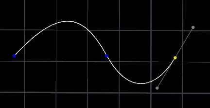
This node also includes an Auto-Bézier point type, similar to Illustrator’s Curvature tool, which lets you guide a curve by placing edit points without having to worry about tangents.
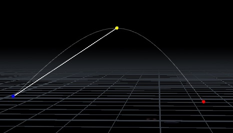
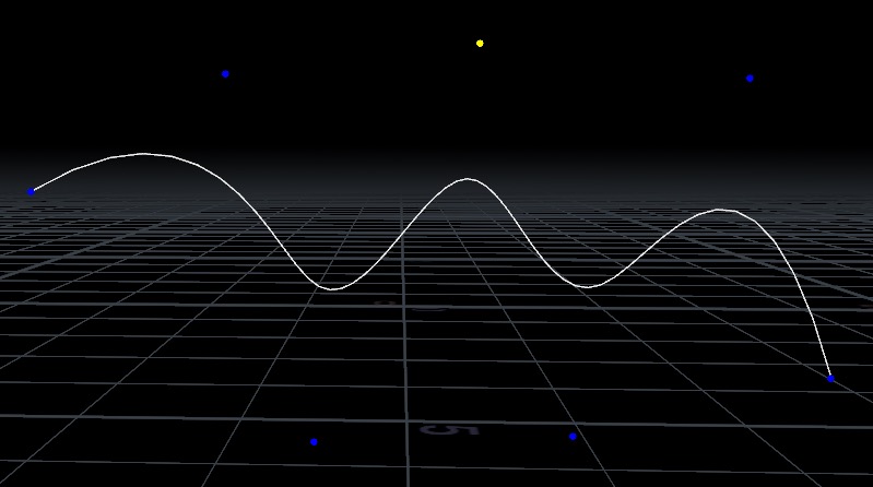
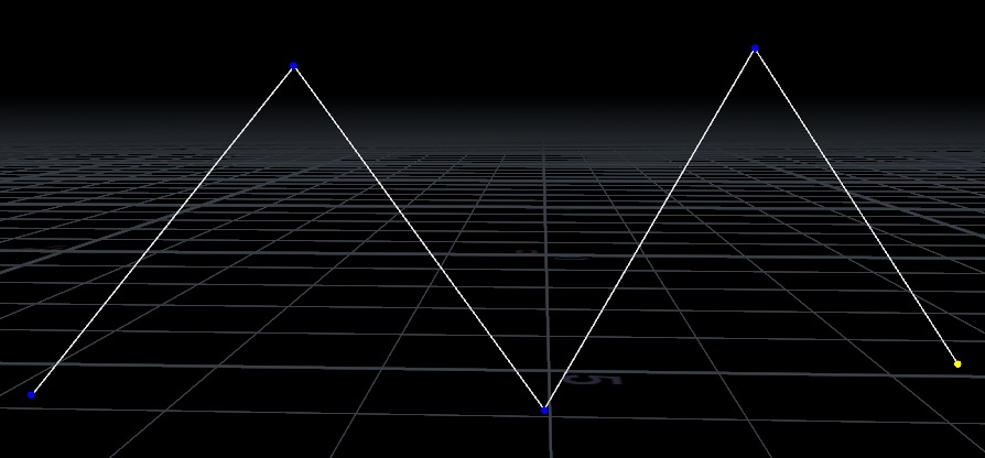
You can also draw polylines, non-cubic orders of Bézier curves, and NURBS. However, when you are drawing these other types, you click to place each point and Houdini interprets the point according to the curve type, without the special support for drawing tangents you get when drawing cubic Bézier curves.
Terms 
Edit points
Also called on-curve points or anchor points. In a Bézier curve, the curve passes through these points.
Tangent handles
Also called control points. In a cubic Bézier curve, these control the direction of the curve going into and coming out of an edit point.
Corner point
An edit point where the tangents have zero length or point in different directions, causing a sharp corner. This is sometimes called having broken tangents.
Smooth point
An edit point where the node keeps the tangents together in a line, so the curve has smooth tangent continuity as it goes through the point.
Balanced point
An edit point where the node keeps the tangents together in a line and also enforces that the tangent points are equal distance from the edit point. This makes the curve have smooth curvature continuity as it goes through the point.
Auto Point
An edit point where the tangents are automatically computed based on the positions of surrounding points and tangents to create a smooth curve. Specifically, the control vertices are computed such that the curve is continuous in both its first and second derivatives (direction and curvature) through these points.
Branch point
An edit point containing multiple vertices.
End Point
An edit point at either end of an open curve.
Tools
While the Curve tool’s state is active, you can be in one of four tools: the Edit tool, the Draw tool, the Orient tool, or the Scale tool. The buttons for these tools are in the operation toolbar across the top of the viewer when the node’s state is active, or you may cycle through them with the F/Shift+F hotkeys.


Using the interactive state 
-
With the Curve node selected, click the
 Handles tool (to the left of the viewer), or move the mouse over the viewer and press Enter.
Note
In Houdini, pressing ⎋ Esc will switch from the active viewer state to the View tool. This can be confusing if you meant to cancel drawing. To get back to the Handles tool (and the curve animate node’s state), make sure the Curve Animate node is still selected, move the mouse over the viewer, and press Enter.
-
The handle in the Curve Animate state is automatically shown or hidden based on the current tool and the selection. By default the handle is turned off. To enable the handle, enable Show Handle in the settings HUD or the parameter pane.
Drawing Bézier curves 
In Draw tool, click or drag in empty space to start a new curve, or click/drag the start or end point of an existing curve to continue drawing the curve. Choose the type of anchors to place with the Draw Type parameter in the Draw tab of the settings HUD or the equivalent parameter in the parameter pane.
| To... | Do this |
|---|---|
|
Place a retracted corner point |
|
|
Place a smooth point |
|
|
Create a straight segment |
|
|
Switch from a straight line to a smooth curve |
|
|
Draw two curve segments connected by a corner (broken tangents) |
|
|
Edit points while drawing |
|
|
Begin drawing from branch point |
|
|
Finish the curve |
|
|
Draw on a surface geometry |
|
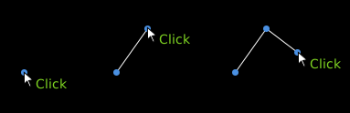
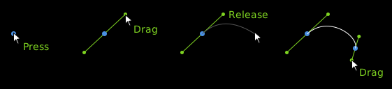
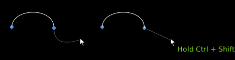

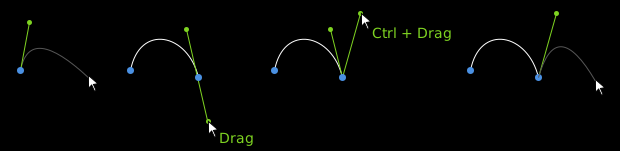


 Close Curve on the
 Drawing with Auto-Bézier points 
When drawing Auto-Bézier points, you can only click to place points (there are no tangent handles). The relative placement of the points controls the direction and curvature of the curve. The preview shows the new shape of the curve if you add a point at the current pointer location.
With some practice, you can learn how to place points (closer together or farther apart) to control the curve’s turning speed and its shape.
| To... | Do this |
|---|---|
|
Add a point |
|
|
Finish the curve |
|
Editing curves 
| To... | Do this |
|---|---|
|
Select a point or points using the Edit tool |
|
|
Make a smooth point into a corner (break tangents) |
|
|
Change points from corner to smooth to balanced |
|
|
Reshape a Bézier curve |
Do any of the following:
|
|
Move a point |
|
|
Move a point in 3D space |
|
|
Move an entire curve |
|
|
Insert a point in the curve |
|
|
Cut a curve at a point |
|
|
Join two open endpoints |
|
|
Join two open endpoints with a line |
|
|
Fuse two points into a branch point |
|
|
Split a branch point into independent points for each vertex. |
|
|
Delete a point |
|
|
Delete a curve segment |
|
|
Reverse a curve |
|
|
Convert a curve to a different type |
|
|
Clear all curves |
|
|
Set colors on curves |
|
|
Set names on curves |
|
|
Copy and paste curves |
|
 Make Corner in the toolbar, or press
  Make Smooth in the toolbar, or press
  Make Balanced in the toolbar, or press
  Make Straight button in the
  Cut Curves at Selected Points.
 Join Selected Points
  Add Segment Between Endpoints.
 Fuse Branch.
 Split Branch.
 Delete Point in the
  Delete Segment.
 To Polygon Hull to convert a NURBs Curve or Bezier Curve to a polygon by reinterpreting the control vertices.
 To Resampled Polygon to convert a NURBs Curve or Bezier Curve to a polygon by resampling the curves. The number of divisions per span is specified by Resample Divs.
 To Bezier to convert a NURBs Curve or a Polygon to a Bezier Curve. When converting from Polygon, if Match Polygon Shape when Converting is enabled, the resulting Bezier will match the polygon shape by inserting extra control vertices, otherwise it will reinterpret the polygon as a Bezier curve.
 To NURBS to convert a Bezier Curve or a Polygon to a NURBs Curve. When converting from Polygon, if Match Polygon Shape when Converting is enabled, the resulting NURBs Curve will match the polygon shape by inserting extra control vertices, otherwise it will reinterpret the polygon as a Bezier curve.
 or in the right click menu click Set Curve Color under Utility.
Creating an Orient Attribute 
In the Orient tool, you can specify target orientation on anchor points by specifying a target Up vector. Attributes for the orientations are then created to smoothly transition in and out of the specified orientations. The resulting attributes use a parallel transport along the curve to determine the orientation for all other points.
To output the orient or axis attributes, turn on Output Quaternion, Output X Axis, Output Y Axis, or Output Z Axis. When any orientation have been created, guide geometry is drawn on curves in the viewport to visualize the attribute. The guide geometry can be shown or hidden with the Show Guide parameter, you can decide which components to show with Guide Components, and the scale of the swept Gnomons for the guides can be customized with Guide Scale.
When in the orient tool, interactive gadgets are available on each of the selected points with a target orientation. By dragging these gadgets, you can rotate the frame around the curve tangent at the point.
| To... | Do this |
|---|---|
|
Add a target orientation point |
|
|
Remove a target orientation point |
|
|
Change all selected orientation points |
|
Creating a Radius Attribute 
In the Scale tool, you can specify target scales on anchor points by specifying target Scale values. A pscale attribute is then created to smoothly transition in and out of the specified target scales. The resulting attribute is then interpolated between target scales to determine the values for all other points. To output the scale attribute, enable Radius Attribute.
When any scales have been created, guide geometry can also be drawn on the curve in the viewport to visualize the attribute. The guide is shared between the orientation and scale tools, showing the orientations and scale factors along the curves. The guide geometry can be shown or hidden with the Show Guide parameter, you can decide which components to show with Guide Components, and the scale of the swept Gnomons for the guides can be customized with Guide Scale.
When in the scale tool, interactive gadgets are available on each of the selected points with a target scale. By dragging these gadgets you can increase or decrease the scale value at a particular point.
| To... | Do this |
|---|---|
|
Add a target scale point |
|
|
Remove a target scale point |
|
|
Change all selected scale points |
|
Animating a Curve 
| To... | Do this |
|---|---|
|
Keying a point on a curve |
|
|
Keying all points on a curve |
|
|
Create animation on a point |
|
|
Animating the orientation or scale |
|
|
Remove a keyframe from the selected points |
|
|
Remove channels from the selected points. |
|
|
Change channel names on the selected points |
|
Operation toolbar 
Tools |
F/Shift+F |
The top level tools available in the state. |
|
|
Edit Tool |
Edit curves, drag points and drag tangents. |
|
|
Draw Tool |
Create new curves or extend existing curves. |
|
|
Orient Tool |
Create orientation attributes on the curves. |
|
|
Scale Tool |
Create pscale attributes on the curves. |
|
|
Delete Points |
⌦ Del |
Remove selected points from curves. |
|
Join Points |
Join two selected end vertices into a single vertex. |
|
|
Cut Points |
Split one vertex into two end vertices. |
|
|
Fuse Branch |
Fuse two or more points into a single branch point. |
|
|
Split Branch |
Split a branch point into multiple points. |
|
|
Delete Segment |
Remove a segment from a curve, leaving two open end vertices. |
|
|
Join Segment |
Join two open end vertices by adding a new curve segment between them. |
|
|
Close Curves |
Close curves by inserting new curve segments between their open end vertices. |
|
|
Reverse Curves |
Reverse the vertices in the selected curves. |
|
|
Corner |
1 |
Convert the selected bezier points into corner points where the tangents are untied. |
|
Smooth |
2 |
Convert the selected bezier points into smooth points where the tangents are colinear. |
|
Balance |
3 |
Convert the selected bezier points into balanced points where the tangents are symmetric. |
|
Auto |
4 |
Convert the selected bezier points into auto points where the tangents are automatically computed to provide continuity in the first and second derivatives through the point. |
|
Retract Points |
Make the tangents attached to the selected points zero length. |
|
|
Expand Points |
Expand out any retracted tangents on the selected points. |
|
|
Straigthen Segment |
Move the tangents on the selected segments to make them straight lines. |
|
|
Flatten to Edit Plane |
Flatten the selected points and tangents to the current edit plane. |
|
|
Space on Circle |
Space all the points on the selected curves around circles. |
|
|
Evenly Space |
Evenly space the selected points. |
|
|
Relax |
Relax the selected points. |
|
|
Straighten |
Project the current selection along a straight line. |
|
|
Set Curve Color |
Change the colors on selected curves. |
|
|
To Polygon Hull |
Convert the selected Bezier and NURBs curves to their polygon hull. |
|
|
To Resampled Polygon |
Convert the selected Bezier and NURBs curves to resampled polygons. The number of divisions is controlled by Resample Divs. |
|
|
To Bezier |
Convert the selected curves to Bezier curves. |
|
|
To NURBs |
Convert the selected curves to NURBs curves. |


Shortcut reference 
C |
Show a radial menu with the commonly used tools and actions. |
K |
Key selected points and create channels if they do not yet exist. If Synchronize Keys per Curve is enabled, all points on the curves with selected points will be keyed. |
F/Shift+F |
Cycle forward or backward through the top level tools. |
Draw Tool 
Enter while drawing a curve |
Finish drawing the curve. |
⇧ Shift + Enter while drawing curve |
Finish drawing curve and close it. |
⌃ Ctrl + ⇧ Shift |
Hold to create a straight line segment while drawing Bézier curves. |
⌃ Ctrl + Drag |
Start curved segment after straight segment. |
⌃ Ctrl while dragging tangents |
Freeze incoming tangent handle in place. |
A |
Hold to create an arc segment while drawing Bézier curves. |
|
Continue drawing existing curve from end point, or join the curve to the end point if already actively drawing a curve. |
|
Begin drawing new curve from branch point, or create a branch point with this point and continue if already actively drawing a curve. |
⌃ Ctrl + |
Insert point into existing curve. |
Edit Tool 
|
Select surrounding anchor points. |
⌃ Ctrl + |
Re-pull tangent handles and make point type balanced. |
⇧ Shift + |
Select entire curve. |
⇧ Shift + |
Move entire curve. |
Drag on curve |
Reshape Bézier curve, or move polyline/NURBS segment. |
1 |
Make selected point(s) corner. |
2 |
Make selected point(s) smooth. |
3 |
Make selected point(s) balanced. |
4 |
Make selected point(s) auto. |
Drag tangent handle line |
Rotate tangent handles without affecting distances. |
⌃ Ctrl while moving points/handles |
Constrain to vertical, horizontal, or diagonal. |
⌃ Ctrl + |
Insert a vertex into the curve at the position under the cursor. |
Ctrl+C |
Copy all curves with any selected points. |
Ctrl+V |
Paste all copied curves to the world position under the cursor on the current Edit Plane. |
Orient Tool 
A with selected |
Create new target orientation point(s). |
⌦ Del with selected points |
Remove target orientation point(s). |
|
Show orient handle on target orientation point. |
|
Rotate target orientations around curve tangent. |
Scale Tool 
A with selected |
Create new target scale point(s). |
⌦ Del with selected points |
Remove target scale point(s). |
|
Show orient handle on target scale point. |
|
Change target scale on the given point. |
Tips and notes 
-
In a Perspective viewport, interactive drawing automatically snaps to the plane the view is facing (or, if the construction plane is active, to the construction plane).
You may want to switch to an orthographic viewport so you can draw on a flat plane without worrying about skew from the camera angle.
-
You can select an edit point or control point and enable Show Handle to show a transform handle to move the point in 3D space.
-
There may be issues with drawing curves in a shaded display mode. The viewer does not do always do a perfect job filling Bezier curves. Even when just drawing polylines, having closed curves be filled/shaded can be distracting. You can press W in the viewer to switch to wireframe mode to view closed curves without shading.
-
You can turn on drag tracers that show the change in position when moving points or tangents in the preferences by turning on Interactive Tools > Show Additional Drag Guides for Interactive States.
-
You can enable Synchronize Keys per Curve to automatically create channels and keyframes on all vertices on a curve whenever any point on that curve is keyed. This is very useful when tracing shapes to ensure all points on the curve are fully keyed so that their positions do not accidentally change when editing a separate keyframe.
Outputs 
The output is a set of curve primitives, each created with the Primitive Type and Order that they were created with. Additionally, if there is any animation created, there is an an Animation packed primitive in the output geometry. This Animation primitive stores the collection of geometry channels that store the animation for each point.
The points are mapped to their geometry channels with the channel_name attribute on the points and the name attribute inside the Animation primitive which stores a prefix (which point it corresponds to) and a suffix (which animation component it corresponds to).
Parameters 
Stashed Geometry
A geometry data parameter storing the current curve geometry and animation.
Reset All Changes
Press to reset all changes and animation.
Apply Keys
Whether to apply geometry channels to the output geometry.
State Settings 
General Settings 
Live Update Mode
Whether to update the output continuously during interactive drags or only on mouse-up.
Synchronize Keys per Curve
When on, keep keys synchronized across all points on each curve. This will create new keyframes on any channel belonging to points on that curve if another channel on that curve has an existing keyframe at that time.
Edit Plane
The plane that points are placed on and drags are computed with respect to.
Axis Aligned
Use the XY, YZ, or XZ plane that is most orthogonal to the view direction.
View Plane
Use the plane normal to the view direction.
Show Preview Curve
When to show the additional preview drawable. By default it is set to During Interactive Operations which will only show the preview curve while dragging in edit mode or drawing in draw mode. Alternatively, by setting it to Always, you can make this extra drawable always be shown which may be helpful when tracing images or drawing on other geometry.
Edit Settings 
Show Handle
Whether to show the handle to control the selected points.
Approximate Bezier Shape after Delete
When deleting points on bezier curves, whether to move the tangents of the resulting segment to best approximate the overall shape from before the deletion.
Match Polygon Shape when Converting
When converting from Polygon to Bezier or NURBs, whether to keep the over all polygon shape by inserting new control vertices, or to instead reinterpret the polygon as the Bezier or NURBs curve hull.
Resample Divs
The number of divisions per span when resampling from Bezier or NURBs to polygon.
Enable Soft Transform
Whether to use soft transform when transforming points in edit mode.
Soft Transform Radius
The soft transform radius applied when transforming points in edit mode.
Draw Settings 
Primitive Type
The type of primitive to create when creating new curves in draw mode.
New Anchor Type
The type of bezier anchor points to create when drawing new points in draw mode.
Order
The order of the curves to create when creating new curves in draw mode.
Orient and Scale Settings 
Show Orient Guide
When to show the orientation and scale guide.
Orient Guide Components
Which components of the orientation and scale guide to show.
Orient Guide Scale
The scale applied to the orientation and scale guide geometry.
Change all Selected Orientations and Scales
Whether to rotate or scale all selected orient or scale points when dragging the handles in their respective modes.
Output 
Output Channel Primitives
Whether to include the Animation data in the output geometry, including the Channel Name Attribute and the Animation packed primitive containing the channel primitives.
Animation Primitive Name
The name given to the animation packed primitive that stores all of the geometry channels that define the curve animation.
Channel Name Attribute
The name of the point attribute on the curves that specifies which geometry channel primitive drives each point’s animation.
Output Corners Group
Whether to output the corner points as a group.
Corner Points
The name of the group to store the corner points in.
Output Smooth Group
Whether to output the smooth points as a group.
Smooth Points
The name of the group to store the smooth points in.
Output Auto Group
Whether to output the auto points as a group.
Auto Points
The name of the group to store the auto points in.
Output Scale Group
Whether to output the scale points as a group.
Scale Points
The name of the group to store the scale points in.
Output Orient Group
Whether to output the orient points as a group.
Orient Points
The name of the group to store the orient points in.
Tangent Type
How to compute the tantent on the curves.
Output X Axis
Whether to output the X axis.
X Axis
The name of the attribute to store the X axis in.
Output Y Axis
Whether to output the Y axis.
Y Axis
The name of the attribute to store the Y axis in.
Output Z Axis
Whether to output the Z axis. This is the vector attribute that stores the tangent as computed by Tangent Type.
Z Axis
The name of the attribute to store the Z axis in.
Output Quaternion
Whether to output the quaternion orient attribute.
Quaternion
The name to give the quaternion orient attribute.
Enable Output Radius
Whether to output the pscale attribute.
Radius Attribute
The name of the output pscale attribute.
| See also |
 Curve 3D
 Add
Add
 Spline Fit
 Convert
 Edit
Edit