Examples 
Add 
AddItUp Example for Add geometry node
This network demonstrates the many uses of the Add SOP to build and manipulate geometry:
-
It is used to create points in space which can then be used to create polygons using designated patterns. These polygons can be open or closed. Futhermore, each point can be animated through expressions or keyframes.
-
It is used to both create points and grab points from other primitives. These points may be used in polygon creation.
-
The Add SOP may be utilized to create a polygon using points extracted from another polygonal object. A Group SOP allows for the creation of the point group that will be referenced by the Add SOP.
-
The Add SOP is used to create a polygon from a group of animated Null objects. An Object Merge SOP references the null points in SOPs which are then fed into an Add SOP for polygon generation. A Fit SOP, in turn, is used to create an interpolated spline from the referenced null points. The result is an animted spline.
-
The Add SOP is used to generate points without creating any primitives. Also, points from other objects can be extracted through the Add SOP.
-
Finally the Add SOP can additionally be used to procedurally create rows and columns.
Agent Relationship 
AgentRelationshipBasic Example for Agent Relationship geometry node
This example demonstrates how to create a simple parent-child agent setup.
Agent Vellum Unpack 
SimpleCrowdCloth Example for Agent Vellum Unpack geometry node
This example demonstrates a simple workflow for simulating cloth on a crowd of characters using the Vellum solver.
Spline Align 
AlignTube Example for Spline Align geometry node
This example demonstrates how the UV information on surfaces, NURBS in this example, are used by the Align SOP to orient one object to another’s surface.
UV reference parameters in the Align SOP can be animated as shown in the align_tube example.
Animating UV parameters leads to the translation and rotation of the aligned geometries along one another’s surface in various ways.
APEX AutoRig Component 
This example demonstrates building blend shape sliders for a facial rig with the blend shape rig component, including single, dual, and 2D patch sliders, and a screen space slider panel that stays locked to the viewport.
NeckComponent Example for APEX AutoRig Component geometry node
This example demonstrates how to use the neck rig component for the Otto test geometry.
RigCharacter Example for APEX AutoRig Component geometry node
This example demonstrates how to use pre-built rig components to build up a rig for Electra.
RootComponent Example for APEX AutoRig Component geometry node
This example demonstrates how to use the root rig component to add root controls for the Electra test geometry.
APEX Graph 
APEXGraphExamples Example for APEX Graph geometry node
This example demonstrates how to create APEX graphs that perform basic numerical operations, as well as build functionality for the animate state, including controls, hierarchies, constraints, and geometry deformation.
Assemble 
PackedFragments Example for Assemble geometry node
This example shows how you can break a sphere into packed objects for use in a rigid body simulation using the Assemble SOP.
Attribute Composite 
BlendAttr Example for Attribute Composite geometry node
This example demonstrates how to blend attributes using the Attribute Composite SOP.
Attribute Copy 
AttribCopyTessel Example for Attribute Copy geometry node
This is an example of how to transfer attributes from one geometry to another using the AttribCopy SOP.
A “smiley face” is painted onto a grid as a color attribute using the Paint SOP. The attribute is then transferred to another grid. Because of a discrepancy between the sizes of the grid, a tesselation occurs.
When there are differences between the sizes of the geometry, the AttribCopy SOP will repeat the pattern of the attribute in a cyclic fashion.
Attribute Create 
CurveTexturing Example for Attribute Create geometry node
The AttribCreate SOP can be used to provide various object-specific attributes by allowing both a label and a value to be given to the newly created attribute.
In this example, the AttribCreate SOP is used to control the width of a curve at rendertime. There are two versions, chosen by a Switch SOP.
-
One AttribCreate SOP gives a constant width attribute in the X axis.
-
The other uses an expression to control the thickness of the curve to create a tapering effect.
The attribute is used by Mantra at render time. To see the results, right-click on the render icon in the viewport, and choose “render_example”.
Attribute Fade 
FadedTorus Example for Attribute Fade geometry node
Here is an example of accumulating and fading an attribute
Attribute Fill 
AttribFillDiffuse Example for Attribute Fill geometry node
This example shows how to use the Blur (Diffuse) mode to spread out an attribute from source points along the mesh and prevent diffusing past UV boundaries.
AttribFillEikonal Example for Attribute Fill geometry node
This example shows how to use the Arrival Time (Eikonal) mode to compute the distance along edges from source points to all other points on the mesh.
AttribFillInterpolate Example for Attribute Fill geometry node
This example shows how to use the Interpolate (Poisson) mode to interpolate the interior point colors given only the colors on the boundaries of a grid.
AttribFillParallelTransport Example for Attribute Fill geometry node
This example shows how to use the Extrapolate (Transport) mode with with extrapolation type set to parallel transport to transport a vector along a surface.
Attribute From Pieces 
AttributeFromPiecesForest Example for Attribute From Pieces geometry node
This example shows how to use the Attribute from Pieces SOP to assign pieces with an attribute indicating size.
AttributeFromPiecesModes Example for Attribute From Pieces geometry node
This example demonstrates the behaviour of the different Mode options in the Attribute from Pieces SOP.
Attribute from Volume 
DeformVolume Example for Attribute from Volume geometry node
Here’s a simple example showing how you can deform a volume. First create a 3d grid of points with the box sop with divisions matching the resolution of the volume. Next, transfer the density from the volume on those points. Finally, the points can be deformed any way you want, and then you can create an empty volume and fill it with the densities from the points.
attribfromvolume Example for Attribute from Volume geometry node
This example demonstrates how the AttribFromVolume SOP can be used to transfer volume values onto point attributes.
Attribute Paint 
PaintingAttributes Example for Attribute Paint geometry node
This Attribute Paint examples demonstrates mirror painting, painting on a low-res surface and transferring it to a hi-res surface, and performance adjustments you can make while painting on a hi-res surface.
Attribute Promote 
AttribPromoteSphere Example for Attribute Promote geometry node
This example demonstrates how the AttribPromote SOP can be used to transfer (promote) attributes between points and primitives.
Attribute Remap 
RampRemap Example for Attribute Remap geometry node
Attribute Remap gives you complete control over your float type attributes mapping them to any range you wish. Great for shrinking the range down, up, linearizing them or cyclically repeating the attribute across it’s original range. You can map any input range to an output range. This gives you familiar control to the reamp VOP or fit() vex functions in an artist friendly manner. A bonus ramp is added for finer shaping of the results. Works great to remap noise.
Attribute Reorient 
CopyUsingOrient Example for Attribute Reorient geometry node
This example demonstrates how to use the Attrib Reorient SOP to calculate rotations applied to points. These rotations are used by the Copy SOP when creating each instance.
Attribute String Edit 
RandomMaterial Example for Attribute String Edit geometry node
This example demonstrates how to use the Attrib String Edit SOP to modify String primitive attributes and randomize the colours on a grid on a per-primitive basis.
Attribute Transfer 
NormalsAttribTransfer Example for Attribute Transfer geometry node
The AttribTransfer SOP may be used to transfer various point attributes from a source geometry to a target. In this case, the normal attributes, N[3], of one grid are transferred to another grid.
TransferColor Example for Attribute Transfer geometry node
The Attribute Transfer SOP can be used to transfer color attributes from one geometry to another. The effective field of transfer can be controlled through the various parameters in the Attribute Transfer SOP.
Attribute Rename 
AttributeRename Example for Attribute Rename geometry node
This is an example of how the Attribute SOP is used to delete and rename attributes within Houdini. Attributes may also be renamed for proper RIB outputs for Renderman.
Attribute Wrangle 
AddPoint Example for Attribute Wrangle geometry node
This example shows you how to add a single new point using the Attribute Wrangle SOP and the addpoint() vex expression.
CentroidPoints Example for Attribute Wrangle geometry node
This example shows you how the primintrinsic method can be used to obtain the number of vertices for a primitive. The point corresponding to a vertex can be obtained by first translating a primitive-vertex offset pair to a linear vertex value then looking up the point referenced by the linear vertex value.
Bake Volume 
FluffyTorus Example for Bake Volume geometry node
This example shows how to setup the Bake Volume SOP to compute the lightfield created by the shadowing of a fog volume. It then exports the fields properly to be rendered in Mantra by a constant volume shader.
Bend 
FlounderBend Example for Bend geometry node
This example demonstrates how to use the new Bend node to bend a flounder.
Blast 
TorusBlast Example for Blast geometry node
This network contains a simple example of how the Blast SOP can be used to delete elements of your model.
The Blast SOP can be used to delete points, edges, polygons and breakpoints using designated patterns.
Blend Shapes 
BlendColors Example for Blend Shapes geometry node
This network utilizes the Blendshapes SOP to morph one geometry’s colors into another’s color.
Two input blend shapes act as inputs for the Blendshapes SOP.
The Blendshapes SOP interpolates all designated attributes, in this case “Cd” between the various inputs.
Play the animation to see the effect.
PolyBlend Example for Blend Shapes geometry node
The Blendshapes SOP is used to blend shapes and/or attributes from input geometry.
In this case, three input morph targets are used by the Blendshapes SOP with the Differencing and Blend Position options checked.
The blend values of the input morphs is keyframed for specific effects. Play the animation to see the results.
Block End 
NumbersOnPoints Example for Block End geometry node
This node shows how to stamp numbers onto points. It uses a for-each loop to iterate over each point, and the metadata source to get the current iteration number.
SimpleFeedback Example for Block End geometry node
This shows how to re-apply the same sequence of nodes multiple times to geometry using the for-loops.
SwissCheese Example for Block End geometry node
This node shows how to iterate over all the pieces of one geometry to consecutively subtract volumes from an original geometry.
Bound 
BoundingBox Example for Bound geometry node
This example demonstrates how to create a bounding box from geometry.
Box 
BoxSpring Example for Box geometry node
The Box SOP is used for more than just creating boxes. It can also envelop existing geometry for specific purposes.
The Box SOP can either create a simple six-sided polygon box, calculate the bounding box size for geometry, or be used in conjunction with the /nodes/sop/lattice.html SOP.
There are two objects within the box.hip file that are examples of this:
-
animated_bounding_box
The animated_bounding_box object shows how you can envelope an object and surround it with a simple box, even if it is animated. This can be useful when displaying complicated geometry, in which case you would put the display flag on the box object and the render flag on the complicated geometry.
-
box_spring_lattice
This is an example, a /nodes/sop/lattice.html SOP used in conjunction with the Box SOP. The Box SOP is used to envelope some geometry, in this case a sphere. Divisions is checked to create the proper geometry by referencing the number of divisions in the /nodes/sop/lattice.html SOP.
The top points of the box are grouped by a Group SOP. The Spring SOP uses these points as the Fixed Points from which to create the deformation.
Using the Box SOP in this way allows you to change the incoming geometry (the basic_sphere in this case) and have the box and lattice automatically re-size for you.
Bulge 
BulgeCat Example for Bulge geometry node
Create a simple cat head by using the Bulge SOP combined with metaballs and a NURBS sphere.
BulgeTube Example for Bulge geometry node
The Bulge SOP is used to deform geometry using a metaball as a magnet force.
The magnitude of the magnet force can be adusted in the Bulge SOP.
The parameters in the Metaball SOP may also be adjusted to modify the final effect of the Bulge SOP on the deforming geometry.
Cache 
SlowParticles Example for Cache geometry node
This file uses the Particle SOP to create a stream of particles.
Then using the Cache SOP, the particles are slowed down. The Cache SOP has the ability to control the frame rate of an animation and read the animation slower than the global frame rate
Spline Cap 
CapCarousel Example for Spline Cap geometry node
This example shows how to cap two designated areas of a geometry by creating groups.
Two Group SOPs are used to create two groups, group_bottom and group_middle. These groups are created using Number Enable. The Pattern number corresponds to the primitive number, which you can see by turning on primitive numbers.
Two Cap SOPs are used to cap the two groups. By capping either the First V Cap or Last V Cap, you can select which end of the group you want to cap.
CapTubeExamples Example for Spline Cap geometry node
This example contains different variations on how to cap a tube.
There are three geometry types that are able to be capped – NURBS, mesh, and Bezier.
Each geometry type contains examples of different cap types – faceted, shared, rounded, and tangential.
For a better description of cap types, please open the help card in the Cap SOP.
Capture Attribute Unpack 
VexDeform Example for Capture Attribute Unpack geometry node
This is an example of how to use the Capture Attribute Unpack SOP to turn capture attributes into something accessible to VEX. It then provides methods to smooth the capture attributes and deform them entirely in VEX.
Carve 
CarveExtractCurve Example for Carve geometry node
This network is a demonstration of how the Carve SOP can be used to extract various elements of the surface geometry.
Depending on the type of geometry, the Carve SOP may be used to extract points from polygonal objects or curves from NURBS surfaces.
Furthermore, the Carve SOP uses the surface U and V information to extract the various elements, and by animating the U and V values we can create various effects as the points and curves move on the geometry surface.
CopySpikes Example for Carve geometry node
This network contains an example of how the Carve SOP can extract 3D Isoparametric Curves from a surface, and how those curves may be used as a copy template.
The Carve SOP can be used to slice a primitive, cut it into multiple sections, or extract points or cross-sections from it.
In this example, the Extract option has been used to Extract 3D Isoparametric Curve(s). A series of disk-like shapes are created as the Carve SOP extracts curves from points around the surface with the same V Directional value.
It then uses the points along those curves as a template on which to copy sourced geometry.
DiscCarve Example for Carve geometry node
This network is a demonstration of the Carve SOP, specifically when dealing with extracting curves from a NURBs surface and animating that extraction.
The Carve SOP uses the U and V surface data to carve the geometry.
In our example we have extracted curves which can then be used as basis for other geometry to create interesting effects.
Given the Carve SOP uses a 0 to 1 value to carve either in the U or V surface direction, that value can be animated either by keyframing or through expressions.
Chain 
ChainBasic Example for Chain geometry node
This example creates a simple chain and train track using the Chain SOP.
Channel 
BlobbySphere Example for Channel geometry node
This is a simple example of how to utilize the Channel SOP to bring information from CHOPs into SOPs and apply it to geometry.
We use an animated sphere and create a lag in the animation of selected areas of the sphere.
In a CHOP network, the Geometry CHOP brings in point position data of the sphere geometry and runs it through a Lag CHOP for the delaying effect. The Channel SOP then references the Lag CHOP and applies the point data back to the selected areas of the original NURBS sphere.
ChannelSOPColorExample Example for Channel geometry node
This example demonstrates using CHOPs to drive geometry color values via the Channel SOP.
Circle 
CircleExamples Example for Circle geometry node
This is an example of the different geometry types and arc types a circle can have.
Geometry types include primitives, polygons, NURBS, and Beziers.
Arc types include closed circle, open arc, closed arc, and sliced arc.
The arc examples are animated, so playback the animation to see the arcs opening.
Circle from Edges 
CircleFromEdgesBasic Example for Circle from Edges geometry node
This example shows how to transform a selection of edges on a tube into a circle and then relax them slightly to preserve geometry.
Spline Clay 
ClayBasic Example for Spline Clay geometry node
This demonstration contains four examples of how a Clay SOP is used. The points have been animated to better visualize this.
Matrix - Point transformation is given by a matrix.
Vector - Point is translated along a vector.
Point - Point is moved to an absolute XYZ position in object space.
Primitive - Point snaps to the (U,V) of the primitive in the 2nd input of to a (U,V) on itself if no 2nd input is present.
Clip 
ClipParticle Example for Clip geometry node
This is a very basic example of how the Clip SOP can be used to control particle flow by cutting it with an infinite plane.
Play animation to see the effects.
ClipVariations Example for Clip geometry node
This network compares the various ways in which the Clip SOP can be used with geometry. Depending on what parts of the clipped geometry we want to keep, different effects are achievable.
The Clip SOP can also be used as a grouping tool by specify group boundaries with clip planes.
Clip planes can be animated. Play the animation to view the results.
Cloth Deform 
CaptureDeform Example for Cloth Deform geometry node
This example demonstrates how you can use the Cloth Capture and Cloth Deform nodes to transfer the simulation from a low-res piece of cloth to a hi-res piece of cloth.
Cloud Billowy Noise 
simple_clouds Example for Cloud Billowy Noise geometry node
This example demonstrates the use of a collection of cloud tools to generate a variety of clouds.
Cluster Points 
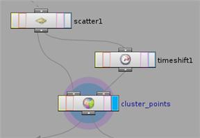
Animated source points Example for Cluster Points geometry node
If you cluster point source geometry with a changing number of points, the clusters and cluster numbers can change randomly at each frame and you’ll get strange results. To prevent this, you must use a couple of tricks to create the clusters based on the final number of points, and only create the clusters that are needed.
First, connect the second input of the Cluster Points node to specify a set of point positions at which the Cluster Points node should cluster the points. This is called the rest position.
For example, the Impact analysis tool creates points from RBD object collisions. The number of points in the resulting geometry increases as more RBD objects collide.
-
Cache the impact points geometry to disk using a ROP Output driver and File node combination.
(The example file may not cache to disk for the sake of simplicity.)
-
Branch a Timeshift node from the File node, and connect the output of the Timeshift to the Cluster Points node’s second (rest position) input.
-
Set the Timeshift node’s Frame parameter to the frame you want to cluster at, usually the last frame of the effect. You can use the
$NFRAMESvariable, which always contains the number of the last frame in the scene.
Second, to create the smoke boxes only as they're needed you must turn on Continuous on the Smoke Object node. This will create a new smoke box on each instance point at every frame. To work around this so the boxes only get created at the frame where the cluster center appears, the example file uses a For Each SOP to delete every cluster center at every frame except the frame where it first appears.
See also how to make scattered points stick for how to make scattered point positions and numbers consistent across frames on deforming geometry.
Collision Detect CL 
CollisionDetectCLVisualization Example for Collision Detect CL geometry node
This example file shows how to visualize collisions between triangles output from the Collision Detect CL SOP.
Comb 
CombGrass Example for Comb geometry node
This example shows how to use the Comb SOP to control the direction of point normals by interactively “painting” over the normals.
Two Comb SOPs are used to comb the normals on a grid in different directions. A Sequence Blend SOP blends between the two so that the normals look like they are swaying.
A simple line geometry is attached to those points.
The Comb SOP is a great way to animate things like hair and grass.
Connectivity 
ConnectedBalls Example for Connectivity geometry node
This example demonstrates how to use an attribute generated by the Connectivity SOP to color different pieces of geometry from a DOPs simulation.
Convert 
ConvToTrimSurface Example for Convert geometry node
This example shows how to create a trimmed NURBS or Bezier surface using the Convert SOP.
There are four examples contained that compare how a trimmed surface handles a texture.
-
Grid Surface a simple texture map on a grid.
-
Trimmed Circle Using the Trim SOP the conventional way of creating a trimmed surface using a Project SOP and a Trim SOP.
-
Trimmed Circle Using the Convert SOP creates a trimmed surface using a Convert SOP.
-
NURBS Surface Using the Convert SOP shows how a texture is parametrized over a surface that is not trimmed.
To get a better sense of the parameterization of the texture, turn on points and toggle between wireframe and shaded modes.
ConvertBasic Example for Convert geometry node
This example shows the various ways in which the Convert SOP converts geometry types using a simple sphere.
A chart is used for this demonstration.
The left column of the chart describes the original geometry type to convert from.
The top row of the chart describes the geometry type to convert to.
All Sphere SOPs and Convert SOPs in this demonstration use their default values to better visualize the differences.
CurveToPrimCircle Example for Convert geometry node
This example is a simple demonstration on how to convert a curve into a primitive circle.
To convert a NURBS or Bezier closed curve to a primitive circle, it must first be converted to a polygon.
Once converted to a closed polygon curve, you can convert the curve to a primitive circle.
Potatochip Example for Convert geometry node
This example demonstrates how to convert a closed curve into a surface using the Convert SOP.
There are two versions contained in this example. One curve has been successfully converted to a surface, the other has not because of the concave shape of the original curve.
View in shaded mode to get a better sense of this.
Convert Line 
ClothingCurves Example for Convert Line geometry node
This example demonstrates how to use the Convert Line node to create curves from edges.
/nodes/sop/cookie 
This example displays the various ways in which a Cookie SOP operates.
This example demonstrates how to perform boolean operations using the Cookie SOP.
In this instance, the points are consolidated using a Facet SOP and a Divide SOP is used to create a smooth surface for the Cookie SOP to operate on.
This example creates a boolean operation using the Cookie SOP.
A star geometry is created and used to subtract the shape from the sphere geometry.
/nodes/sop/copy 
The Copy SOP can be used for more than copying geometry. In this example, the Copy SOP is used to transfer color attributes from the template geometry (or point) to the copied geometry.
A polygonal sphere with color infomation is used as the source geometry. A point with a color attribute (Cd) is extracted from the sphere and used as a template by the Copy SOP. Then the Copy SOP transfers the color infomation to a copied polygonal circle.
The Copy SOP is used to transfer specific attributes from a template to copied primitives. In this example, a sphere is use as a template with color attributes added to the sphere points. A Particle SOP is then used to birth particles from the sphere points.
Next, a Copy SOP does two things:
-
It copies geometry to the particles.
-
It transfers the color attribute from the source sphere points to the geometry whose position is based on the particles.
Play the animation to see the effects.
The Copy SOP is used to copy geometry to particles using the Particle SOP as a template. In the example, the Scale parameter of the Copy SOP is used to create the specific effect. The Copy SOP may also be used to control different attributes of the copied geometry beyond mere scale.
Play the animation to see the effects.
In this example, the Copy SOP is used to randomly copy various objects onto points of a given template geometry. We use the stamp capability of the Copy SOP for our purpose. Furthermore, the entire process is kept procedural so that we have the option of determining the type and the number of geometries to be copied and the kind of template to be used.
Inside the Stamp tab of the Copy SOP we create a variable named “switch” which will drive the input value of the Select Input parameter in the Switch SOP. In turn, the Copy SOP is able to copy at random any number of input geometry to template points.
This example demonstrates the power of the Copy SOP’s Stamp operation.
Here, a Copy SOP is used to copy a circle onto the points of a sphere. The Stamp operation then applies various modifications to those copies based on division, scale, color, and extrusion. This results in the generation of a randomized variety of “stars”.
Starting with a simple circle, a large number of variations are created using in the copies through the use of Stamping with expressions.
Crease 
CreaseBasic Example for Crease geometry node
This demonstration contains four different examples of applying the creaseweight attribute to polygonal geometry utilizing the Crease SOP, Vertex SOP, Attribute Create SOP, and Subdivide SOP.
It also points out some of the differences between rendering with Mantra vs. RenderMan. It is important to know that Mantra can not render the creases due to Copyright laws.
Note
Rendering creases with Mantra requires the addition of a Subdivision SOP for calculating the geometry. The Render tab’s Geometry parameter at the object level should be set to: Geometry As Is.
If Renderman is being used, the Subdivide SOP is only for previewing the result. Renderman calculates creases during the render. The Render tab’s Geometry parameter at the object level should be set to: Polygons as Subdivision Surfaces.
Spline Creep 
CreepBlob Example for Spline Creep geometry node
This example shows how to creep metaballs on a surface. In this case, the surface is a contorted tube and the metaballs look like a “blob” being pushed through the tract.
A tube is created and used as the creep surface. A circle is created by carving a profile out from that same tube. The circle is then animated with a Creep SOP down the length of the tube.
Metaballs are attached to the points on that carved circle to create the “blob”.
CreepParticleTubeA Example for Spline Creep geometry node
This example shows two different ways in which particles can be crept on a surface. In this case, the surface is a contorted tube.
One version shows how particles are crept inside the surface, the other shows how particles are crept outside the surface. This is done by changing the z scale in the Creep SOP, which offsets the particles perpendicular to the surface.
The particles are birthed from a circle that is carved from the tube geometry.
CreepSpiral Example for Spline Creep geometry node
This example shows how to spiral a line geometry over a tube surface using the Creep SOP.
CreepText Example for Spline Creep geometry node
In this example, some text geometry is creeped along an animated surface.
The surface is comprised of two skinned curves that have been animated using a Sequence Blend SOP. The Creep SOP requires that the creep surface be a surface and not a curve.
CreepWeave Example for Spline Creep geometry node
This example shows how you can take a geometry and creep it over an animated surface.
A file, fabric.bgeo, which looks like woven fabric, has been brought in using the File SOP. A NURBS grid has been animated to look like a piece of waving fabric using sine and noise functions.
The fabric.bgeo is crept over the animated NURBS grid, using a Creep SOP, and the result is an animated piece of woven fabric.
Crowd Assign Layers 
This example demonstrates how to create several layers with different geometry variations and randomly assign those layers to agents.
Crowd MotionPath Evaluate 
This examples demonstrates how to generate motion paths from a simulated crowd, and use Crowd MotionPath Edit to interactively adjust the paths of specific agents.
This example demonstrates how the Crowd MotionPath Avoid SOP can be used to
apply avoidance between neighboring agents and against obstacles, and also uses
the collisionignore attribute to build more complex avoidance rules and
collision filtering between different groups of agents.
Crowd MotionPath Follow 
This examples demonstrates how to deform motion paths to follow guiding curves, along with more advanced options such as following closed loops and using attributes to control which curves are followed by each agent.
Crowd MotionPath Trigger 
This example demonstrates how to use the Crowd MotionPath Layer SOP to layer a clip onto the upper body of an agent. The clip is activated when the agent is inside a bounding object.
This example demonstrates how to use the Crowd MotionPath Transition SOP to blend between animation clips, including intermediate transition clips defined by a clip transition graph
Crowd Source 
PopulateRandomAgents Example for Crowd Source geometry node
This example demonstrates how populate a crowd with several different types of agents.
Curve 
ChainCurve Example for Curve geometry node
This example provides a walkthrough of creating an HDA that wraps Curve SOP together with Chain SOP and correctly promotes all parameters of Curve along with the state.
/nodes/sop/curve- 
This example demonstrates how to use the Curve SOP to create a car’s hood. It also shows how to make points on a new curve dependent on the points of a previous curve. This way, you can move the points on one curve and affect any curve further in the network.
Spline Curve Clay 
CurveClayBasic Example for Spline Curve Clay geometry node
This is a demonstration of how the CurveClay SOP can create an embossed effect on nurbs or bezier geometry.
Two different methods of using the CurveClay SOP to imprint font onto a sphere are shown.
The first method uses a single projected profile, the second method uses two profiles.
UltraSharpFont Example for Spline Curve Clay geometry node
This example demonstrates how to refine a curveclay geometry.
A letter “t” is projected onto a grid. The CurveClay SOP understands profile information and uses it to deform the surface geometry.
To get sharp edges on a curveclay, play with the Sharpness and Refinement parameters.
Delete 
DeleteDemo Example for Delete geometry node
This example demonstrates how the Delete SOP is used to remove specified geometry from a scene.
Geometry may be deleted by Point or Primitive Numbers, by Group, or by position within a Bounding Box.
DeltaMush 
DeltaMushDemo Example for DeltaMush geometry node
This example demonstrates how the Delta Mush SOP is used to smooth out bone deformation.
Dissolve 
DissolveBox Example for Dissolve geometry node
This example shows how the Dissolve SOP is used to remove points, edges or primitives of a geometry. The Dissolve SOP automatically patches any holes remaining after the dissolution of various elements.
Distance along Geometry 
DistanceDriver Example for Distance along Geometry geometry node
This example demonstrates how the Distance Along Geometry node can be used to find the shortest distance along edges or surfaces.
Distance from Geometry 
SurfaceDistance Example for Distance from Geometry geometry node
This example demonstrates how the Distance From Geometry node can be used to measure distances between surfaces or distances between points and surfaces.
Divide 
RemoveSharedEdges Example for Divide geometry node
The Divide SOP is capable of removing edges from geometry. In this example a Divide SOP removes all the internal edges from a simple grid.
DOP Import Records 
dopimportrecordsexample Example for DOP Import Records geometry node
This example demonstrates a creating points for each matching record in the DOP simulation. This lets us create a point for each object or a point for each impact.
/nodes/sop/duplicate 
The Duplicate SOP, in this example, is used to create multiple iterations of a box geometry with each copy scaled and offset cumulatively. Expressions using copy number $CY may be used to control each iteration’s parameters.
Edge Collapse 
EdgeCollapseBasic Example for Edge Collapse geometry node
The Edge Collapse SOP simply allows the deletion of edges, as shown in this example. Point numbers are rearranged to accommodate the missing edge.
Edge Cusp 
EdgeCuspStairs Example for Edge Cusp geometry node
The Edge Cusp SOP is a quick way to create distinct edges on a model during render time. Edge Cusp creates the edges by uniquing shared edge points and recomputing point normals.
Edge Divide 
EdgeDivideBasic Example for Edge Divide geometry node
This is a simple example of the different ways the EdgeDivide SOP is used to insert points on the edges of polygons.
Edge Equalize 
EdgeEqualizeBasic Example for Edge Equalize geometry node
This example shows how to equalize the edges in a selection so that they are all the same length as the smallest edge in the selection.
Edge Flip 
EdgeFlipBasic Example for Edge Flip geometry node
This example demonstrates how you can use the EdgeFlip SOP to flip a selected edge on a surface.
An edge is created on a polygon using the Polysplit SOP, then rotated using the EdgeFlip SOP.
Edge Fracture 
EdgeFracture Example for Edge Fracture geometry node
This example shows various ways of fracturing along the edges of an input mesh using the EdgeFracture SOP.
Edge Straighten 
EdgeStraightenBasic Example for Edge Straighten geometry node
This example shows how to transform a path of edges on a sphere so that they lie on a straight line.
Edit 
ReferenceGeometry Example for Edit geometry node
This example creates an animation illustrating how the Edit SOP’s Reference Geometry input can be used to apply an edit on animated geometry.
TerrainEdit Example for Edit geometry node
This example demonstrates how to create a terrain using the Edit SOP.
Extract Transform 
ExtractAnimatedTransform Example for Extract Transform geometry node
This example shows how to create packed primitives with animated transforms from deforming geometry that represents rigid motion. The result is ideal for colliders in a rigid body simulation.
Extrude 
ExtrudeFont Example for Extrude geometry node
This is an example of the Extrude SOP. It illustrates how volume and geometry are created from flat primitives.
It also demonstrates how to separate parts of the geometry into groups, and how to apply different shaders to each group.
Facet 
FacetVariations Example for Facet geometry node
This example shows the different ways to use the Facet SOP to let you control the smoothness or faceting of a given object. It also shows how you can consolidate points.
Press the right arrow key to show each example.
/nodes/sop/falloff 
This example demonstrates how to measure distance on a model using Falloff, then create a custom deformer using that distance attribute to drive the amount the model is deformed.
File 
PackedPoints Example for File geometry node
This example shows how you can use the file sop to do a delayed load of packed disk primitives to have multiple geometry samples per frame for rendering motion blur. If you save out the packed disk geometry, you're really only saving out the point geometry with references to the disk files (which is very light weight).
PackedSamples Example for File geometry node
This example shows how you can use the file sop to do a delayed load of packed primitives to have multiple geometry samples per frame for rendering motion blur.
PackedSequence Example for File geometry node
This example shows how you can use the file sop to load a packed disk sequence.
Spline Fillet 
GridFillet Example for Spline Fillet geometry node
The Fillet SOP is used to create a bridge between two NURBS surfaces with control over its parameterization. The fillet uses the original surface uv information for bridging.
Fillet types may include Freeform, Convex or Circular. The Freeform fillet usually provides a smooth natural form. Such parameters as the left and right UV, Width, Scale, and Offset may be used to control the fillet location between the surfaces.
Find Shortest Path 
DirectedEdgesPath Example for Find Shortest Path geometry node
This is an example of how to use the FindShortestPath SOP to find a path through geometry where certain edges are directed edges. Directed edges can only be traversed in one direction.
Try changing the start and end points, as well as the directed edges, to explore how the SOP avoids going the wrong direction, and cannot reach points with only outgoing edges.
PathAnalysis Example for Find Shortest Path geometry node
This is an advanced example of how to use the FindShortestPath SOP to prefer “central” paths, based on centraily measures computed using FindShortestPath and AttribWrangle. This helps avoid staying too close to walls where avoidable.
Turn on the Display Option > Optimization > Culling > Remove Backfaces to see inside the space more easily. Try visualizing the different centrality measures using the switch node. The same example without considering the centrality of the path is demonstrated in a side branch of the SOP network, in order to see the difference.
Spline Fit 
FitCurves Example for Spline Fit geometry node
This is an example of how to use the Fit SOP to fit a NURBs curve to a basic polygon curve.
Fitting builds a new NURBs or Bezier curve through the input geometry’s points.
There are two methods for doing this:
Interpolation fitting outputs the same number of cv’s as the input curve (Original Polygon Curve).
Approximation fitting reduces the number of cv’s, while approximating a curve through the input points.
Play the animation to see how these two methods affect the resultant curve over time.
FitSurfaces Example for Spline Fit geometry node
This contains examples of fitting a Polygon Mesh to a NURBS surface through the use of the Fit SOP. There are two methods of fitting:
-
Approximation, which generates primitives that roughly follow the path of the data points.
-
Interpolation, which generates primitives that touch all the data points.
/nodes/sop/fluidsource 
This example demonstrates how you can use the Fluid Source SOP to source and advect colours from an additional volume into a smoke simulation.
This example demonstrates how to cool Lava using the Cool Within Object shelf tool.
This example demonstrates how you can use the Fluid Source SOP to create a volume for fluid simulations from a torus.
Font 
BubblyFont Example for Font geometry node
The Font SOP is used to create 3D text geometry in the scene.
The geometry may be set to Polygon, Bezier, or a combination of the two.
With the combination, Bezier will be used for letters containing curves, and Polygon will be used for those with only straight edges.
Fonts other than those loaded by default may be loaded in the Font parameter.
Force 
ForceBasic Example for Force geometry node
This example file uses the Force SOP in conjunction with Metaball SOPs and Particle SOPs to create dynamic animations.
Using the Radial Force Parameter of the Force SOP, particles are puffed in and out. Then, using the Directional Force Parameter, a rotating vortex is created as a metaball spins around an axis.
Press play to view the animation.
/nodes/sop/foreach 
This example demonstrates how to get around a common problem with For Each in “Merge” mode where the primitive ordering can be drastically changed by the For Each loop (when all you really want to do is add an attribute).
This example demonstrates three different methods of using the ForEach SOP: group, number, and attribute value.
This example uses the ForEach SOP in all three modes (by group, by attribute and by iteration) for you to study and use. You can make any SOP that doesn’t support local variables (like Magnet, for example) behave like one that does using any of the three methods shown here.
This example shows how to use the For Each SOP to individually boolean a bunch of self intersecting spheres with a cheese wedge.
This example shows how to use the foreach sop to intersect one object with each part of another object and merge the results together.
This example uses the foreach sop to apply the same SOP repeatedly to the geometry, accumulating the effect of each pass.
Fractal 
FractalGeoTypes Example for Fractal geometry node
This example demonstrates using the Fractal SOP to deform geometry to get a random, jagged subdivision surface. This is a useful tool in creating things such as bumpy terrains, landscapes, rocks, or debris.
The Fractal SOP is applied to each geometry type to show how the displacement changes based on the geometry type.
Fur 
Clumping Example for Fur geometry node
The Fur SOP is used to instance hair-like curves.
In this case, the Fur SOP is used to create curves that can be used for clumping. A second Fur SOP is used to illustrate how to create hairs that use the clumping geometry.
FurBall Example for Fur geometry node
This example demonstrates how the Fur SOP builds hair-like curves based on guide curves and skin geometry.
FurBallWorkflow Example for Fur geometry node
This example demonstrates how the Fur SOP and Mantra Fur Procedural can be applied to an animated skin geometry. CVEX shaders are used to apply a custom look to the hairs based upon attributes assigned to the geometry.
FurPipelineExample Example for Fur geometry node
This example illustrates how custom shaders can be used to define the appearance of fur generated by the Fur SOP.
FurRandomScale Example for Fur geometry node
This example demonstrates how a CVEX shader can be used to apply procedural effects to the curves generated by the Fur SOP. All attributes from the Fur SOP’s guide geometry and the skin geometry inputs are made available to the CVEX shaders. The CVEX shader makes use of the attributes, a unique identifier for each curve, “fur_id”, and the position of each point, “P”.
FurTextureMap Example for Fur geometry node
This example demonstrates how to use a texturemap to color fur.
Fuse 
Glue Cluster 
glueclusterexample Example for Glue Cluster geometry node
This example shows how to use the gluecluster SOP and glue constraint networks to cluster together the pieces of a voronoi fracture. This allows clustering to be used with Bullet without introducing concave objects.
Graph Color 
FindNonInteractingAgents Example for Graph Color geometry node
This example demonstrates how the Graph Color SOP can be used to partition a crowd into groups of agents that did not interact with each other (based on a collision radius) during the simulation. When adding secondary cloth simulations to a crowd, this can be useful for avoiding unwanted collisions from nearby agents.
Grid 
/nodes/sop/group 
This example demonstrates how feature edges of your object can be preserved during a polyreduce by using an Edge Group.
Group Copy 
GroupCopyBox Example for Group Copy geometry node
This example demonstrates how to group geometry based on a group from another network.
Group Expand 
GroupExpandBasic Example for Group Expand geometry node
This example shows how to use group expand to expand a group of primitives while restricting growth by normal spread angle.
Group Find Path 
GroupFindPathBasic Example for Group Find Path geometry node
This example shows how to create a path between a sequence of edges that is closed and avoids specified primitives.
Group from Attribute Boundary 
GroupFromAttribBoundaryBasic Example for Group from Attribute Boundary geometry node
This example shows how to create a group of edges from the boundaries of a group and the boundaries of a color attribute.
Group Transfer 
TransferProximity Example for Group Transfer geometry node
This example demonstrates how to use the proximity of a group’s primitives to transfer the group to a new set of geometry using the Group Transfer SOP.
/nodes/sop/heightfield_erode-2.0 
Hole 
IsoOffset 
Brickify Example for IsoOffset geometry node
This example shows how to 'brickify' or make an object appear to be made of bricks using the IsoOffset SOP.
SquabVolume Example for IsoOffset geometry node
This example demonstrates the use of the Volume Visualizer on the Squab test object which has been converted to a volume using isooffset.
Join 
BasicJoin Example for Join geometry node
This example demonstrates how the Join SOP can connect multiple pieces of geometry by faces and surfaces.
The Join SOP will combine the individual pieces of geometry into a single primitive that will inherit attributes.
Nurbs, Bezier, or Mesh surfaces should be used with the Join SOP.
Do not use Polygons as it will not work with the Join SOP.
Agent Animation Unpack 
AgentClipToMotionClip Example for Agent Animation Unpack geometry node
This example demonstrates converting agent clips into SOP MotionClips, editing the animations using MotionClip tools, and then importing the modified MotionClips into the agent definition.
Agent from Rig 
AgentFromSOPs Example for Agent from Rig geometry node
This example demonstrates how to build an agent from a SOP rig, including importing geometry, ragdoll collision shapes, joint limits, and setting up animation clips.
Agent Pose from Rig 
TransferPoseToAgent Example for Agent Pose from Rig geometry node
This example demonstrates how to transfer poses from a SOP skeleton to agent primitives, using several different modes of the Agent Pose from Rig SOP.
Attach Joint Geometry 
capturegeoexample Example for Attach Joint Geometry geometry node
The example demonstrates using attached joint geometry to influence the capture result of biharmonic capturing. This method can be more efficient then purely painting weights and gives you more control over influence areas per joint in comparison to purely joint position based biharmic capturing.
-
Created the capture geo shapes with common SOP nodes and use the Merge Packed SOP node to bundle and pack them
-
Connect the output of the Merge Packed SOP node to the second input of the Attach Joint Geo node
-
Enter the viewport state, click the joint in your skeleton that you want to assign the world space shape to as a control, press-hold G, and then
 -click the world space shape that you want to assign to the joint.
 -
Connect the output of the Attach Joint Geo SOP node to the second input of the Joint Capture Biharmonic node
-
In the Parameter Editor, set the Role to the role set by the Attach Capture Geo SOP node. The capture geometry will be automatically used for the solve of the biharmonic capturing. You can bypass it via the Use Capture Geo Joints toggle
Character Blend Shapes 
InbetweenShapes Example for Character Blend Shapes geometry node
This example demonstrates adding and using in-between blend shapes in the character blend shapes workflow.
SimpleCharacterBlendShapes Example for Character Blend Shapes geometry node
This example demonstrates importing a character with blend shapes, adjusting the channel values, and then applying a blend shapes deformer.
Configure Joint Limits 
ConfigureLimitsFromMotionClip Example for Configure Joint Limits geometry node
This example demonstrates how to configure joint limits using MotionClips. It provides a basic clip that, once retargeted to your own biped character, can be used as a starting point for the rotation limits. It also showcases a more interactive alternative to configuring limits when no external clip is available.
Dynamic Warp 
DynamicWarpRemoveStalls Example for Dynamic Warp geometry node
This example demonstrates how to use the DynamicWarp node to fix a jogging animation that has several stalls.
MotionClip 
SimpleMotionClip Example for MotionClip geometry node
This examples demonstrates how to create a motion clip from a skeleton animation.
MotionClip Blend 
SimpleMotionClipBlend Example for MotionClip Blend geometry node
This example demonstrates how to use the MotionClip Blend node to blend an animation of someone being pushed while running forwards into an animation of someone jogging around a corner.
The final result is an animation of someone being pushed while jogging around a corner.
MotionClip Cycle 
SimpleMotionClipCycle Example for MotionClip Cycle geometry node
This example demonstrates how to use the MotionClip Cycle node to cycle an animation of someone jogging around a corner while maintaining the momentum of the character.
MotionClip Evaluate 
SimpleMotionClipEvaluate Example for MotionClip Evaluate geometry node
This example demonstrates how to use the MotionClip Evaluate node to evaluate the pose of the motion clip at the current frame of the scene.
MotionClip Extract 
SimpleMotionClipExtract Example for MotionClip Extract geometry node
This example demonstrates how to use the MotionClip Extract node to extract a series of frames from a motion clip.
MotionClip Pose Delete 
SimpleMotionClipPoseDelete Example for MotionClip Pose Delete geometry node
This example demonstrates how to use the MotionClip PoseDelete node to remove a series of frames from a motion clip.
MotionClip Pose Insert 
SimpleMotionClipPoseInsert Example for MotionClip Pose Insert geometry node
This example demonstrates how to use the MotionClip PoseInsert node to alter the pose of a frame in a motion clip.
MotionClip Retime 
SimpleMotionClipRetime Example for MotionClip Retime geometry node
This example demonstrates how to use the MotionClip Retime node to crop an animation and alter its playback speed.
MotionClip Sequence 
SimpleMotionClipSequence Example for MotionClip Sequence geometry node
This example demonstrates how to use the MotionClip Sequence node to sequence two motion clips and create a smooth transition between the two clips.
MotionClip Update 
SimpleMotionClipUpdate Example for MotionClip Update geometry node
This example demonstrates how to use the MotionClip Update node to raise the shoulder joints of a motion clip.
Rig Attribute VOP 
CameraOnPath Example for Rig Attribute VOP geometry node
This example demonstrates how to use the KineFX Transform from Path, Blend Transforms, and Offset Transform VOPs in SOP to constrain a camera on a path.
CurveSolverVop Example for Rig Attribute VOP geometry node
This example demonstrates how to use the KineFX CurveSolver VOP in SOP. It does the same as the Follow Curve mode on the InverseKIN CHOP.
IkSolverVop Example for Rig Attribute VOP geometry node
This example demonstrates how to use the KineFX IkSolver VOP in SOP. It does the same as the Inverse Kinematics with Twist Affector mode on the InverseKIN CHOP.
Laplacian 
LaplacianSmoothing Example for Laplacian geometry node
This example demonstrates the use of the Laplacian SOP to smooth an input surface geometry using the classic Laplacian smoothing technique.
Lattice Deform 
BallBounce Example for Lattice Deform geometry node
This is an example of how a /nodes/sop/lattice.html SOP is used to create a bouncing ball.
DeformLattice Example for Lattice Deform geometry node
The /nodes/sop/lattice.html SOP creates animated deformations by manipulating simpler geometry that encloses the source geometry.
This example shows how the /nodes/sop/lattice.html SOP can use an animated Box SOP to deform the source geometry. In this case, the source geometry is a sphere.
LatticePerChunk Example for Lattice Deform geometry node
This example shows how you can use the foreach sop to apply a lattice to each fragment of a sphere.
Lattice from Volume 
PigLattice Example for Lattice from Volume geometry node
This example demonstrates how to create a lattice around volumetric data.
/nodes/sop/layer 
This example demonstrates the use of the layer SOP to layer multiple textures onto a single object.
This example demonstrates how to have multiple shading layers with different uv sets using the Layer SOP and the VEX Layered Surface SHOP.
Line 
LineDirection Example for Line geometry node
This example demonstrates how to generate a line using the Line SOP.
Linear Solver 
ARAPSurfaceDeformation Example for Linear Solver geometry node
This example demonstrates the use of the Linear Solver SOP to apply the As-Rigid-As-Possible surface deformation method.
CurveInflation Example for Linear Solver geometry node
This example demonstrates the use of the Linear Solver SOP to inflate an input 2D domain defined with curves to create a 3D surface geometry.
RBFCageDeformer Example for Linear Solver geometry node
This example demonstrates the use of the Linear Solver SOP to deform an object based on the embedding cage’s deformation using a radial basis function.
SagfreeInitialization Example for Linear Solver geometry node
This example demonstrates the use of the Linear Solver SOP to initialize the Vellum distance constraints so the object will not sag from the gravity.
L-System 
LSystemMaster Example for L-System geometry node
The LSystems SOP allows for the definition of complex shapes through the use of iteration. It uses a mathematical language in which an initial string of characters is evaluated repeatedly, and the results are used to generate geometry. The result of each evaluation becomes the basis for the next iteration of geometry, giving the illusion of growth.
The example networks located in this demonstration should be enough to get you started writing custom LSystem rules.
However, anyone seriously interested in creating LSystems should obtain the book:
The Algorithmic Beauty of Plants, Przemyslaw Prusinkiewicz and Aristid Lindenmayer
For a full list of LSystem commands, see the Houdini documentation.
LsystemBuilding Example for L-System geometry node
This example demonstrates how to use the L-System SOP to generate buildings with windows.
Magnet 
MagnetBubbles Example for Magnet geometry node
This example shows the use of the Magnet SOP, and illustraites its ability to deform geometry.
The Magnet SOP works by using the Density Field of a Metaball as a Magnetic Influence Field on a piece of geometry. The degree to which the Magnetic Field effects the surface it is deforming is based on the distance of that surface to the center of the Metaball.
Here, the Metaballs have been attached to a moving particle system which bounce across a plane. The Metaballs also interact with the plane, causing it to bubble upward as their Fields intersect the surface.
MagnetDistortion Example for Magnet geometry node
This example demonstrates some of the various ways to use the Magnet SOP.
It can be used to affect point position, point color, point normals, and velocity.
Mask by Feature 
MaskByFeatureBasic Example for Mask by Feature geometry node
This example shows how to create a lighting and shadow mask on a pig head using the Mask by Feature SOP.
Match Topology 
MatchTopologySphere Example for Match Topology geometry node
This example demonstrates how the Match Topology SOP lines up the points and primitives between two geometries with equal amounts of points and primitives.
The Tracking Points, Reference Points, and Assume Primitives Match features are utilized to get a perfect match.
MDD 
This example demonstrates how to use the MDD SOP and MDD File Writer ROP.
Measure 
MeasureArea Example for Measure geometry node
This example demonstrates how to create groups based on the area of a primitive using the Measure SOP.
MeasureLaplacian Example for Measure geometry node
This example demonstrates how to measure the Laplacian to smooth or sharpen an attribute.
Merge 
MergeAttributes Example for Merge geometry node
The Merge SOP applies all incoming attributes to all input geometry. Each input geometry may have its own set of attributes.
Three spheres are wired into a Merge SOP. The first has no attributes applied. The second has a color attribute (Cd[3]) applied by a Point SOP. The third has a normal attribute (N[3]) applied by another Point SOP.
The Merge SOP does NOT know how to build attributes, but can apply them. As a result, all applied attribute values are set to zero.
This is why the first two spheres display and render black. They have normal attributes applied, but their values are set to zero.
In addition, the first and last spheres have a color attribute applied, but their values are set to zero.
It is better to set attributes explicitly, instead of relying on the Merge SOP to do so.
Metaball 
BlendMetaballs Example for Metaball geometry node
This is a basic example of how metaballs interact as force fields with a density threshold and falloff. Metaballs can be created in Houdini through the Metaball SOP
The Point SOP is used to provide a visual representation of how metaballs interact when their respective fields blend into one another in an additive fashion.
MetaExpression Example for Metaball geometry node
This example demonstrates how to use a Meta Expression in an Attribute Create SOP to control how metaballs merge together.
Mirror 
MirrorSpout Example for Mirror geometry node
This example demonstrates how to mirror geometry using the Mirror SOP.
Normal 
BoxNormals Example for Normal geometry node
This example uses the Normal SOP to show what point normals and vertex normals look like on 5 types of boxes and on extruded text.
OpenCL 
SimpleOpenCLSOPSnippets Example for OpenCL geometry node
This example file contains a myriad of code samples using OpenCL snippets, demonstrating how they can be used to modify geometry attributes and interact with volume/VDB primitives.
Orientation along Curve 
TankTread Example for Orientation along Curve geometry node
This example demonstrates how the Orientation Along Curve SOP can be used to create a Tank Tread.
/nodes/sop/paint 
This example demonstrates how to use the Paint SOP to paint an attribute onto geometry, and then use the attribute to modify the geometry.
This example demonstrates how to paint color onto geometry using the Paint SOP.
This example demonstrates how to paint scattered points onto the surface of your geometry with a set number of points per area.
/nodes/sop/particle 
This example demonstrates how to create a fluttering leaf simulation by using the Particle SOP.
It also demonstrates how to use the Point SOP to modify point normals, affecting the velocity and direction of particles. Since particles are actually points in space, the Point SOP is a powerful way to control particle attributes.
Press play to watch the simulation.
This example shows the ability of the Particle SOP to define a default Size for any given birthed particle.
A simple Grid can be used to create a dynamic solution of particles streaming off as if blown by the wind. As these particles leave the grid, their size slowly diminishes, as the particle continues to die.
This example file demonstrates using the Metaball and Force SOPs to affect particles generated by the Particle SOP.
Particles are birthed from the origin and shot towards a still metaball. The metaball has a Force SOP applied to it causing the particles, upon reaching the metaball, to spread away from it out into space.
This is a basic example of using the Particle SOP to birth particles at the SOP level, and having the particles collide with geometry.
The given example file takes a grid, and using the Particle SOP in combination with the Metaball and Force SOPs, creates a dynamic animation.
A metaball ship jets through space driving particles out of its path along the wake of the ship. With the help of the Force SOP, the metaballs are given the properties necessary to make this reaction possible.
Play the animation to see the full effect.
This example contains five demonstrations of some of the various uses of the Particle SOP.
-
Creep particles along a surface using a the Creep SOP.
-
Group birth particles from a group of points on a surface.
-
Bounce particles.
-
Split particles on contact.
-
Collide particles off a collision object.
-
Birth particles from a moving object.
-
Use a metaball to exert force on a particle.
This is an example of creating a fountain from several Particle SOPs and basic modeling.
It demonstrates how to create normal offsets, velocity variances, and collision behaviors to control the motion and look of the particles.
This example uses a Metaball SOP and a Force SOP to push particles side to side as they pass through a particle stream generated by a Particle SOP.
Particles are birthed in the air off of a sphere, while a metaball passes back and forth through, pushing the particles from its path.
Play the animation to see the full effect.
The Particle SOP enables the creation of particles at the SOP level and allows those particles to directly interact with geometry. Furthermore, these particles are in turn treated as point geometry.
In this example, particles are both crept along and collided with a collision tube object. It is possible to also manipulate and control particles in SOPs through the adjustment of point normals (including those of the particles).
/nodes/sop/partition 
This example demonstrates how to break geometry in a DOPs simulation using the Partition SOP to determine the DOP Objects.
Path Deform 
PathDeformBasic Example for Path Deform geometry node
This example shows how to deform a squab on the curve and make its claws rigid.
PathDeformPiece Example for Path Deform geometry node
This example shows how to use a piece attribute to assign different geometries to different curves and customize several parameters, such as the size and placement of geometry, on a per-curve basis using attributes.
Peak 
Platonic Solids 
PlatonicSolidsTypes Example for Platonic Solids geometry node
The Platonic Solids SOP generates platonic solids of different types. Platonic solids are polyhedrons which are convex and have all the vertices and faces of the same type. There are only five such objects, which form the first five choices of this operation.
This example shows all seven of the different polyhedron forms that can be made using the Platonic Solids SOP.
/nodes/sop/point 
This is an example of how to use the Point SOP to orient point normals along a path. This allows for control over the orientation of geometry when copied onto points.
Points are extracted along a spiral on a per frame basis using an expression in the Carve SOP. A cone is copied to these points sequentially and results in an animation along the path.
This is an example of how to calculate a cross product by using the Point SOP. The cross product is defined as the vector perpendicular to two input vectors.
To visualize this demonstration, please explore the SOP network and turn on Point Normals in the display.
This example of the Point SOP demonstrates the capacity of the Point SOP to alter geometry based on another input.
A sphere is created and then the points are randomly transformed. Then, by using both inputs of the Point SOP, the original sphere is brought back to average out its altered form. A simple math expression averages the positions of the two spheres, point by point.
The Point SOP is quite a versatile operator. This example shows how the Point SOP may be used to control point weight, color, normals, and UV attributes.
Furthermore, it is possible to create various relationships among the point attributes through the Point SOP.
This is a demonstration of how the Point SOP can be used to add Normals to geometry.
It also shows how the Point Normals affect the orientation of copied geometry and the appearance of shaders.
Using the Point SOP, a simple displacement is created and applied to a portion of a spherical surface.
Using the normals of a point, which is basically a vector, and adding that number to the position of the point, the point is displaced in that given direction. With a Merge and Skin SOP the displaced surface is then connected back to the original.
This example file uses the Point SOP to turn a regular line into a spiral.
There are two different approaches used in this example. The first uses the point numbers of the line to define the expression calculations. The second uses the position of the points in the line’s bounding box for the expression.
The Point Terrain Erode file displays a mountainous landscape, created by the Fractal SOP. The landscape is swiftly worn away by the Point SOP.
With just a spare channel, erode, and a simple clamp() expression, the Point SOP can control the whole land.
This example shows how to use a simple python expression inside a SOP node to deform a grid. The expression imports a python math library and uses noise to deform the points of a grid.
Point Cloud Iso 
TwistyCube Example for Point Cloud Iso geometry node
This example demonstrates how to construct a polygonal surface from a point cloud using the Point Cloud Iso Surface SOP.
Points from Volume 
AlphaOmega Example for Points from Volume geometry node
This example demonstrates how to use a Points From Volume SOP to create a target goal for a flip simulation and make it fill a given piece of geometry.
PolyBevel 
PolybevelBox Example for PolyBevel geometry node
This example demonstrates how to bevel geometry using the Poly Bevel SOP.
/nodes/sop/polycap 
This example demonstrates how to cap off a hole in a piece of geometry using the Poly Cap SOP.
PolyCut 
PolyCutBasic Example for PolyCut geometry node
This is a simple example of some different ways that the PolyCut SOP can be used to break curves based on attribute changes.
Poly Extrude 
PolyextrudeTube Example for Poly Extrude geometry node
This example demonstrates how to extrude geometry using the Poly Extrude SOP, as well as demonstrating the different extrude controls, Global and Local.
PolyHinge 
PolyHingeBasic Example for PolyHinge geometry node
This example shows how to use the polyhinge SOP to extrude a group of faces around a pivot edge.
PolyHingeEdge Example for PolyHinge geometry node
This example shows how to extrude an open curve around a freely positioned pivot line.
/nodes/sop/polyknit 
This example demonstrates the various options for joining polygons using the PolyKnit SOP. The PolyKnit SOP is useful for filling in holes, gaps, or to re-define edges on polygonal geometry.
PolyKnit can be used to manually knit joining polygons between existing polygons. Polygons are created by specifying a list of input points from which to “knit” the new polygons.
PolyKnit will yield different results, depending on the pattern by which the points are selected or listed. Please see the Helpcard documentation for more information on how the PolyKnit SOP builds new polygons.
PolyPatch 
PolyPatchDNA Example for PolyPatch geometry node
This example demonstrates the use of the PolyPatch SOP to procedurally model complex forms.
Here, a DNA model is created.
PolyReduce 
PolyreduceBatwing Example for PolyReduce geometry node
This example demonstrates how to reduce the number of polygons on a piece of geometry using the Polyreduce SOP.
PolySoup 
PolysoupTorus Example for PolySoup geometry node
This example demonstrates how to use the Polysoup SOP to convert a high-res polygonal object into a single primitive that requires less memory.
PolySplit 
PolySplitHood Example for PolySplit geometry node
This example shows how to use the PolySplit SOP to refine the geometry of a car hood by splitting polygons.
PolyWire 
PolywireModel Example for PolyWire geometry node
This example demonstrates how the Polywire SOP builds polygonal geometry based on a polygonal frame, and how the parameters can be customized with local variables.
Primitive Properties 
PrimCenter Example for Primitive Properties geometry node
This is an example of how to use the Primitive SOP to correctly sweep primitives on a curve.
The Sweep SOP places the origin of a primitive on a curve by default. If the primitive centroid is away from the origin, the primitive will be placed away from the curve.
In order to correctly place the primitive’s centroid on the backbone, its centroid must be at the origin. For this, the Primitive SOP is used.
PrimRotate Example for Primitive Properties geometry node
This example demonstrates how to rotate individual primitives on a grid surface using the Primitive SOP.
A Group SOP is used to animate a bounding box over the grid surface, thereby activating the randomized rotations in the Primitive SOP.
PrimitiveColors Example for Primitive Properties geometry node
This example demonstrates using the Primitive SOP to add a Color attribute to primitive geometry.
The rand() function is used in the RGB fields to generate different random colors for each primitive.
Then the prim() function is used to reference the attribute values of one SOP, to drive the attribute values of another SOP.
PrimitiveExplode Example for Primitive Properties geometry node
This file demonstrates the ability of the Primitive SOP to control the individual primitives of the object.
With expressions in the Translate Parameter, motion is created driving the primitives away from their centroid. Yet another expression presents the primitives with a randomized rotation. Another randomizing expression colorizes each of the primitives.
Together these parameter create an explosion destroying the original sphere.
PrimitiveMetaWeight Example for Primitive Properties geometry node
This example demonstrates the how the Primitive SOP can be used to drive the attributes of other geometry. In this case it is used to affect the Weight Parameter of a Metaball SOP.
In addition, the parameter can be animated over time. Press Play to see the animation.
Spline Profile 
FlagProfiles Example for Spline Profile geometry node
This example shows how to use the Project SOP to create a profile on a surface.
The Profile SOP is then used to extract the profile from the surface or remap the profile on it. It also shows how the profile will animate with the surface or independent of it.
Spline Project 
ProjectCurve Example for Spline Project geometry node
This example shows the Project SOP projecting a Circle onto a Tube geometry.
By projecting along a vector the Circle profile is attached to the tube. With the use of a Trim SOP the profile can then be used to cut holes in the Tube.
Pyro Solver 
PyroDensityGravity Example for Pyro Solver geometry node
This example shows how to use the new gravity feature for effecting density on the pyro solver.
PyroPackedRBD Example for Pyro Solver geometry node
This example shows how to make pyro simulations interact with rigid body pieces using packed collider sets.
PyroSimpleUpres Example for Pyro Solver geometry node
This example illustrates the workflow for upressing pyro simulations.
PyroSourceInstancing Example for Pyro Solver geometry node
This example demonstrates how to use pyro instanced sourcing with packed source sets.
PyroUpresDeform Example for Pyro Solver geometry node
Using a deformed low-res simulation to guide a high-resolution simulation using the upres workflow.
Quad Remesh 
QuadRemeshBasicExample Example for Quad Remesh geometry node
This example demonstrates how to retopologize a procedurally modelled volume mesh with the Quad Remesh node.
QuadRemeshGuidingExample Example for Quad Remesh geometry node
Demonstrates a methods for guiding edge flows in Quad Remesh based on a set of UV boundaries.
QuadRemeshReferenceInputExample Example for Quad Remesh geometry node
Demonstrates usage of the reference input on the Quad Remesh node.
Rails 
Ray 
RayWrap Example for Ray geometry node
The Ray SOP projects one object over the surface contours of another.
It does so by calculating the collisions of the projected object’s normals with the surface geometry of the collided object.
In this example, a Grid is wrapped over the surface of a deformed Sphere using the Ray SOP.
A Facet SOP is used to correct the normals of the wrapped Grid after it is deformed over the surface.
RBD Bullet Solver 
GuidedRBDBulletSolver Example for RBD Bullet Solver geometry node
This example demonstrates the use of the RBD Bullet Solver SOP guiding feature.
KatamariDamacy Example for RBD Bullet Solver geometry node
This example demonstrates the use of the RBD Bullet Solver SOP with custom forces, the new sticky constraints and dynamic constraint property editing.
MaterialFractureTutorial Example for RBD Bullet Solver geometry node
This example contains a setup that is used in the tutorial seen here: destruction/tutorials/intro_to_mbd_1
RBDAgeExample Example for RBD Bullet Solver geometry node
This example contains a setup that uses the age parameters(and Age-ing RBD feature)
RBDBulletSolver Example for RBD Bullet Solver geometry node
This example contains a number of various uses for the RBD Buller Solver SOP.
RBDBulletSolverEmission Example for RBD Bullet Solver geometry node
This example demonstrates the use of the RBD Bullet Solver SOP emissions feature.
RBD Cone Twist Constraint Properties 
ConeTwist Example for RBD Cone Twist Constraint Properties geometry node
This example demonstrates the use of the Cone Twist Constraint Properties SOP to setup mechanical Bullet cone twist constraints.
RBD Connected Faces 
RBDConnectedFaces Example for RBD Connected Faces geometry node
This example demonstrates the use of the RBD Connected Faces SOP with its RBD Disconnected Faces counterpart.
RBD Constraints From Lines 
RBDConstraints Example for RBD Constraints From Lines geometry node
This example demonstrates the use of the RBD Constraints from Lines, RBD Constraints from Curves and RBD Constraints from Rules SOPs.
RBD Deform Pieces 
RBDDeformPieces Example for RBD Deform Pieces geometry node
This example demonstrates the use of the RBD Deform Pieces SOP.
RBD Guide Setup 
RBDGuideSetup Example for RBD Guide Setup geometry node
This example demonstrates the use of the RBD Guide Setup SOP in conjunction with the RBD Guide DOP.
RBD Match Transforms 
RBDMatchTransforms Example for RBD Match Transforms geometry node
This example demonstrates the use of the RBD Match Transforms SOP node.
Refine 
BasicRefine Example for Refine geometry node
This example contains a few methods of how the Refine SOP can be used to add or remove detail from many types of surfaces.
Remesh 
Squidremesh Example for Remesh geometry node
This example demonstrates how to use the Remesh SOP to remesh a model of a giant squid crab while preserving the hard edges of the model.
Remesh to Grid 
AdaptiveRemeshToGrid Example for Remesh to Grid geometry node
This example demonstrates how to adaptively remesh geometry using the Remesh to Grid node.
Resample 
ResampleLines Example for Resample geometry node
This example demonstrates the use of the Resample SOP on three types of curves. (Polygon, NURBS and Bezier)
The Resample SOP rebuilds the curve by converting it into a series of Polygon Line Segments.
The curve may be rebuilt “Along Arc” or “Along Chord”. “Along Arc” utilizes the Hull information as a basis of reconstruction, and can be defined by a Maximum Segment Length and/or Maximum Segment number. “Along Chord” can only be defined by Maximum Segment Length.
Resampling the curve based on Maximum Segment number divides the line into segments of equal, but unspecified length, spanning from start to endpoint. Line detail is directly proportional to the Segment number.
Resampling the curve based on Maximum Segment Length will rebuild the entire line into equal length segments except the last segment. If the Maintain Last Vertex option is on, the last segment will be less than or equal to the Maximum Segment Length value, depending on its distance to the endpoint. With the option off, the endpoint is disregarded and the line is created out of equal lengths.
Turn on Points in the display to see how the Resample SOP resamples line segments.
Rest Position 
BasicRest Example for Rest Position geometry node
The Rest Position SOP creates an attribute based on the surface normals that allows a shader to stick to a deforming surface.
All primitives support the rest attribute, but, in the case of quadric primitives (circle, tube, sphere and metaball primitives), the rest position is only translational. This means that rest normals will not work correctly for these primitive types either.
Use the Rest Position SOP only when you are deforming your geometry and you are assigning volumetric or solid materials/patterns in your shader.
Rest normals are required if feathering is used on polygons and meshes in Mantra. NURBs/Beziers will use the rest position to compute the correct resting normals.
It will be necessary to render the setup in order to see the effect.
Revolve 
BasicRevolve Example for Revolve geometry node
This example demonstrates the Revolve SOP’s ability to create geometry by spinning curves and surfaces around any described axis. Simple objects, such as a torus and a vase, are generated by the Revolve SOP and user-defined inputs.
This file also shows off how different geometry types react to different Revolve SOP parameter changes.
Ripple Solver 
RippleFlippy Example for Ripple Solver geometry node
This example demonstrates the use of the Ripple Solver SOP using animated collider geometry to create ripples on a grid.
Sequence Blend 
Birdy Example for Sequence Blend geometry node
The different pieces of geometry, all with the same point count and order, are created. Each piece of geometry is fed into the Sequence Blend SOP in a specific order. Then, the Input Blend parameter is used to animate through the three input morphs using an expression.
BlendPUsingv Example for Sequence Blend geometry node
This example shows how you can blend point positions taking into account their velocities, using the Sequence Blend SOP.
BlendPointAttributes Example for Sequence Blend geometry node
This example shows how to blend point attributes using a Sequence Blend SOP.
BlendPrimitiveAttributes Example for Sequence Blend geometry node
This example shows how to blend primitive attributes using a Sequence Blend SOP.
BlendVertexAttributes Example for Sequence Blend geometry node
This example shows how to blend vertex attributes using a Sequence Blend SOP.
Scatter 
DoorWithPolkaDots Example for Scatter geometry node
This example demonstrates how you can use the Scatter SOP to scatter points that stay consistent through topology changes like remodelling the input geometry or breaking it. It does this by using the option to scatter in texture space.
GrassGrow Example for Scatter geometry node
This simple example demonstrates how you can use the Scatter SOP to randomly scatter grass across a basic terrain.
SpikyDeformingTorus Example for Scatter geometry node
This example demonstrates how you can use the Scatter SOP with the Attribute Interpolate SOP to easily adjust scattered points to stay consistent on deforming geometry.
SpottedSoccerBalls Example for Scatter geometry node
This example demonstrates how you can use the Scatter SOP to scatter points that stay consistent when separate pieces are added or removed. It does this by using the option to use custom random seeds for each primitive.
Scatter and Align 
ScatterAlignBasic Example for Scatter and Align geometry node
This example shows how to scatter points on a grid with random scaling and rotations, and then scatter smaller points around the initial points.
Shallow Water Solver 
CanyonFlooding Example for Shallow Water Solver geometry node
This example contains a simulation network to flood canyon terrain using the shallow water solver.
ShallowWaterFountain Example for Shallow Water Solver geometry node
This is a simple example that uses the shallow water solver to fill a fountain.
Skin 
SkinBasic Example for Skin geometry node
This is a demonstration of using the Skin SOP to create complex forms by creating surfaces between one or two input geometries.
It also demonstrates how the Skin SOP can interpret between different geometry types and varying point numbers.
SkinCurves Example for Skin geometry node
This demonstration contains example networks showing 3 different methods by which the Skin SOP can assemble input curves to produce a variety of forms.
The methods covered in this demonstration are how the Skin SOP can make a form from a single asymmetrical curve, based on grouping primitives, or from multiple curves.
SkinGroup Example for Skin geometry node
This example demonstrates how you can use the Skin SOP to skin geometry in two different ways: By groups of primitives and by skipping every nth primitive.
SkinShip Example for Skin geometry node
This example displays a creative use for the Skin SOP involving the creation of an alien ship.
Curves are first created with the Curve SOP. Then, with the Skin SOP individual curves can be selected to be used as reference for a generated surface.
SkinSurfaceCopies Example for Skin geometry node
This is an example of how to create a new surface using the Skin SOP.
Here a surface is extracted from a torus, copied and used to create a skin that shoots up from the torus.
Smooth 
/nodes/sop/solidfracture 
This example demonstrates using SolidFracture to split tetrahedra for welding and breaking with the Vellum Solver.
Solver 
CircleSolvers Example for Solver geometry node
This example demonstrates various ways in which you can use a solver node to transform an object based on ordinary differential equations.
There are 6 different solvers in this example. There is also the exact answer as a point of reference. The solvers are numerical methods that solve the following coupled Ordinary Differential Equations with initial conditions:
x' = y ; x(0) = 1
y' = -x ; y(0) = 0
The numerical methods for Ordinary Differential Equations are: Forward Euler, Runge-Kutta Second Order, Runge-Kutta Third Order, Runge-Kutta Fourth Order, and Parker-Sochacki solved two ways. In one version, Parker-Sochacki is hard coded at order 5. In another version Parker-Sochacki is written in a for loop where the order can be adjusted by the user.
Footsteps Example for Solver geometry node
This is an example of simple footsteps using sdfs on a grid.
SimpleCloth Example for Solver geometry node
This is an example of a simple cloth using verlet integration and simple explicit springs.
Sphere 
SphereTypes Example for Sphere geometry node
This example shows all the geometry types the Sphere SOP can create and explains the differences between them.
Choosing the right geometry type can make a network flow and render much faster.
Spiral 
BoltSpiral Example for Spiral geometry node
This example demonstrates how to use the new Spiral node to create a bolt.
Spray Paint 
Splurgegun Example for Spray Paint geometry node
This example shows how to pipe a metaball into a spraypaint sop to create a splurgegun that you can paint with.
/nodes/sop/spring 
This network utilizes three SOPs (Bound, Spring and Lattice) that commonly work together to simulate certain physical dynamics.
We have created a simple polygonal sphere to act as the source geometry. The sphere is then fed into a Bound SOP which will act as a deforming reference. The Bound SOP also behaves as re-enforcement for the deforming object.
Then the bounding box is wired into the Spring SOP with a group of grids as collision objects. The Spring SOP simulates the dynamics by calculating the proper deformations and behaviours of our source geometry as it collides with other objects. The Spring SOP is where we can apply external forces along with various attributes (characteristics such as mass and drag) which influence how the object deforms.
Finally the /nodes/sop/lattice.html SOP takes the deformation information from the Spring SOP and applies it to the source sphere geometry.
This example demonstrates the three main functions of the Spring SOP.
It shows how the Spring SOP can deform input geometry to create a cloth like effect by creating interactions between two objects, defining motion, and applying forces.
Play the animation to see the Spring SOP in action.
This example shows how a flag can be simulated using a Spring SOP.
Here the Spring SOP applies forces that simulate the laws of physics on the points of a Grid SOP to create the flag effect.
This example demonstrates a way to create dynamic hair using the Spring SOP.
A Line is copied onto the points of a Sphere and input into the Spring SOP as a source. Then a Metaball and Force are input to further effect the motion of the hair.
Here the Spring SOP is used to give a line rubber band-like characteristics. Used in combination with an Xform SOP, the rubber band dances about on the floor.
Stitch 
StitchGrid Example for Stitch geometry node
This example demonstrates how the Stitch SOP can join the edges or surfaces of geometry.
A grid is created and duplicated in a stair fashion. Then the Stitch SOP is used to connect them together.
Subdivide 
SubdivideCrease Example for Subdivide geometry node
This example shows a couple ways that you can keep the creases on the top of a box while subdividing the bottom.
Spline Surfsect 
SurfsectBasic Example for Spline Surfsect geometry node
This example demonstrates the use of the Surfsect SOP’s boolean operation.
First a box is used to subtract from a Sphere leaving 4 disks. Then the Sphere is used to subtract from the Box leaving just the corners.
Sweep 
SweepBasic Example for Sweep geometry node
This example demonstrates how the Sweep SOP copies geometry onto the points of a curve.
The Sweep SOP is unique in that it automatically places the copied geometry perpendicular to the backbone it is copied to. Variations such as the Cross Section’s scale can be adjusted using expressions.
SweepCurve Example for Sweep geometry node
This network contains an example of the Sweep SOP. A NURBS curve and NURBS circles are used as the backbone and the cross section geometries of the sweep operation respectively.
By controling the scaling of the cross section geometry in the Sweep SOP various effects can be acheived. Finally, a Skin SOP completes the form by using the swept geometry as a kind of skeleton.
SweepDome Example for Sweep geometry node
In this example the Sweep SOP a grid is used as the backbone of a sweep operation with arcs (created by a Circle SOP) as the hull (cross sections) of the sweep object.
The final sweep object is then skinned with a Skin SOP to create the dome geometry.
WigglyWorm Example for Sweep geometry node
This network demonstrates how the Sweep SOP can be used to construct geometry that is easily deformable. The Sweep SOP requires a backbone and cross section geometry.
Through a sin() function an expression is created to animate the backbone for a slithering effect. Then the circles are copied at every point on the backbone to create the skeleton of the worm. Finally, a simple skin operation completes the worm body.
Tangent Field 
TangentFieldExample Example for Tangent Field geometry node
This example demonstrates how to use the Tangent Field node on a mesh.
TangentFieldGuidingExample Example for Tangent Field geometry node
Demonstrates a couple different methods for guiding tangent fields.
Test Geometry: Electra 
TestGeometryElectraAnimate Example for Test Geometry: Electra geometry node
This example demonstrates the basic setup to animate and render Test Geometry: Electra using APEX Scene Animate and Solaris.
Texture Feature 
TextureFeatureBasicExample Example for Texture Feature geometry node
This example demonstrates how to use the Texture Feature node with some example image data.
Texture Optical Flow 
TextureOpticalFlowBasicExample Example for Texture Optical Flow geometry node
This example demonstrates how to use the Texture Optical Flow node with some example image data.
TimeShift 
PlateBreak Example for TimeShift geometry node
This example demonstrates how to use the TimeShift SOP to achieve a slow-motion effect during a fracture simulation.
Topo Landmark 
TopoLandmarkBasic Example for Topo Landmark geometry node
This example demonstrates how to use the Topo Landmark node with some example scan data and Topo Transfer.
Topo Transfer 
TopoTransferBasic Example for Topo Transfer geometry node
This example demonstrates how to use the Topo Transfer node with some example scan data.
Torus 
TorusExamples Example for Torus geometry node
This example contains the various geometry types possible when creating a torus.
Triangulate 2D 
Chainmail Example for Triangulate 2D geometry node
This example demonstrates advanced use of the new Triangulate2D SOP to create chainmail links.
/nodes/sop/twist 
This example shows off the flexibility of the Twist SOP. The Twist SOP has many operations such as twist, bend, shear, taper, linear taper, and squash.
Contained are examples of how each Operation affects different geometry types: Polygon, Mesh, NURBs, NURBs Perfect, Bezier, and Bezier Perfect.
Unpack 
UnpackWithStyle Example for Unpack geometry node
This example demonstrates the Unpack SOPs ability to evaluate style sheet information while unpacking. Nested packed primitives are used to demonstrate partial unpacking while still preserving styling information. This example also demonstrates the use of a Python SOP to extract information from the per-primitive style sheets.
Unsubdivide 
PigHeadUnsubdivide Example for Unsubdivide geometry node
This is an example that demonstrates basic features of the unsubdivide node. It covers some common use cases and explains more in details the intention of each parameter.
UV Project 
ProjectionTypes Example for UV Project geometry node
This example demonstrates the various projection types supported by the uvproject SOP.
UV Transform 
SoftRotate Example for UV Transform geometry node
Animate the rotation of texture coordinates using the UV Transform SOP with a soft falloff.
Press Play to see the animation.
Vellum Drape 
CorrectOverlapDrape Example for Vellum Drape geometry node
This example demonstrates using the Vellum Drape SOP to find a valid starting position for initially overlapping cloth.
Vellum Rest Blend 
BasicRestBlend Example for Vellum Rest Blend geometry node
This example demonstrates different ways to update Vellum constraints' rest states from geometry using Vellum Rest Blend.
Vellum Solver 
AnimatedConstraints Example for Vellum Solver geometry node
This example demonstrates animating Vellum constraint properties during simulation.
AnimatedPressure Example for Vellum Solver geometry node
This example demonstrates using the pressurescale attribute to create an animated inflation effect with the VellumSolver’s pressure constraint.
ArmLayer Example for Vellum Solver geometry node
This example demonstrates using the layer point attribute to improve collisions when simulating multiple layers of Vellum cloth.
ArmTarget Example for Vellum Solver geometry node
This example demonstrates using Pin to Target constraints to attract Vellum cloth to capture / deformed geometry.
CollisionDisable Example for Vellum Solver geometry node
This examples demonstrates using the disableexternal attribute to disable Vellum collisions on a point-by-point basis.
CollisionIgnore Example for Vellum Solver geometry node
This examples shows to use point attributes to directly control collisions with collisionignore and collisiongroup.
DynamicAttach Example for Vellum Solver geometry node
This example shows how to create Attach to Geometry constraints during a Vellum simulation based on proximity to a collision object.
DynamicStitchGlue Example for Vellum Solver geometry node
This example demonstrates dynamically stitching or gluing Vellum geometry together during a simulation.
GluedGrains Example for Vellum Solver geometry node
This example demonstrates gluing Vellum Grains together for sticky particle effects.
HairOrient Example for Vellum Solver geometry node
This example shows the most efficient and stable way to update the orientation for hair guides going into the Vellum Solver when used outside the standard Grooming tools.
ResolutionTarget Example for Vellum Solver geometry node
This examples shows how to target a hi-res Vellum cloth simulation to a previous low-res simulation to maintain overall motion while still getting fine wrinkles.
SimpleWeld Example for Vellum Solver geometry node
This example demonstrates simple breaking welds for tearing cloth using the Vellum solver.
StiffnessDropoff Example for Vellum Solver geometry node
This example demonstrates creating softly releasing Pin constraints using the Stiffness Dropoff parameter.
TetrahedralFiber Example for Vellum Solver geometry node
This example demonstrates the Tetrahedral Fiber constraint for simulating contracting softbodies.
VaryingFriction Example for Vellum Solver geometry node
This examples shows to use point attributes to get varying friction in Vellum cloth simulations.
VellumFluidPhasesReference Example for Vellum Solver geometry node
This example contains is a complete setup for creating interacting Vellum fluids with different Viscosity and Surface Tension settings through the Phase parameter.
VellumFluidPhasesStart Example for Vellum Solver geometry node
This example contains the necessary objects to create interacting Vellum fluids with different Viscosity and Surface Tension settings through the Phase parameter.
VellumFluidSetupGeo Example for Vellum Solver geometry node
The objects in this file are required to follow the workflows in Vellum fluid setups.
/nodes/sop/vertexsplit 
This example uses the Vertex Split SOP to add sufficient points for copying vertex texture coordinates to point positions.
Visibility 
VisibilityCheckers Example for Visibility geometry node
This example demonstrates the how the Visibility SOP can hide or expose selected primitives in the 2D or 3D view ports.
Volume Analysis 
volumeanalysis_curvature Example for Volume Analysis geometry node
This example shows how to use the Volume Analysis SOP to compute the curvature of a volume and colour the original points from the curvature values.
volumeanalysis_grad Example for Volume Analysis geometry node
This example shows how to use the Volume Analysis SOP to compute the gradient of a volume and displace the geometry’s points by the gradient.
Volume Blur 
volumeblur Example for Volume Blur geometry node
This example demonstrates how the Volume Blur SOP can be used to apply local filters to volume values, such as blurring, dilating, or eroding.
Volume Compress 
volumecompress Example for Volume Compress geometry node
This example shows how to use the Volume Compress SOP to reduce the memory requirements of volumes without too adversely affecting their appearance.
Volume Deform 
SquabTwist Example for Volume Deform geometry node
This example demonstrates how to deform volumetric data.
Volume Feather 
volumefeather Example for Volume Feather geometry node
This example shows how to use the Volume Feather SOP to smooth sharp volumes either in a purely outwards or purely inwards direction.
Volume from Attribute 
volumefromattrib Example for Volume from Attribute geometry node
This example shows how to use the Volume From Attrib SOP to transfer point attributes into volume voxels.
Volume Merge 
DetectOverlap Example for Volume Merge geometry node
This example shows how to detect the overlapping regions of many incoming volumes procedurally using Volume SOP and Volume Merge SOP.
volumemerge Example for Volume Merge geometry node
This example shows how to use the Volume Merge SOP to flatten multiple instanced volumes onto a single camera frustum volume.
Volume Rasterize Lattice 
PigBend Example for Volume Rasterize Lattice geometry node
This example demonstrates how to deform volumetric data.
Volume Reduce 
barycenter Example for Volume Reduce geometry node
This example shows how to use the Volume Reduce SOP to compute the barycenter of a 3d object.
Volume Resample 
volumeresample Example for Volume Resample geometry node
This example shows how to use the Volume Resample SOP to increase and decrease the resolution of a volume. It also shows how the different sampling options affect the quality of the resulting volume.
Volume Stamp 
GridStamp Example for Volume Stamp geometry node
This example shows how to use the Volume Stamp SOP to copy volumes onto the points of a grid.
Volume Surface 
volumesurface_explicitgrade Example for Volume Surface geometry node
This example shows how to use the Volume Surface SOP to surface an SDF using another volume to specify the triangle sizes.
volumesurface_hierarchy Example for Volume Surface geometry node
This example shows how to use the Volume Surface SOP to surface a hierarchy of SDFs using explicit grading.
volumesurface_simple Example for Volume Surface geometry node
This example shows how to use the Volume Surface SOP to surface an SDF using adaptive triangle sizes.
Volume VOP 
ImportVolumes Example for Volume VOP geometry node
This example shows how to import multiple volumes into a Volume VOP SOP.
Voronoi Split 
VoronoiSplitWeights Example for Voronoi Split geometry node
This example demonstrates using the Weight Attribute option on the Voronoi Split SOP to create a power diagram.
Winding Number 
WindingPighead Example for Winding Number geometry node
This example demonstrates use the Winding Number SOP in a variety of ways on the Pighead test geometry.
Wire Blend 
Wireblend Example for Wire Blend geometry node
The Wire Blend SOP is used to blend curves from input geometry. In this case, three input morph targets are used by the Wire Blend SOP with the Differencing and option checked. The blend values of the input morphs are keyframed for specific effects. Play the animation to see the results.
Wire Capture 
BasicWireCapture Example for Wire Capture geometry node
This example demonstrates set up a basic wire capture network.
Wire Deform 
TwistWireDeform Example for Wire Deform geometry node
This example demonstrates how to define local coordinate frames for use with the Wire Deform SOP.
Transform 
ModulusTransform Example for Transform geometry node
Create a cyclical animation using the Transform SOP, the Group SOP, and the modulus operation.
Transform Pieces 
TransformFracturedPieces Example for Transform Pieces geometry node
This example demonstrates using the Transform Pieces SOP to transform high-resolution geometry from the results of a rigid body simulation that used low-resolution geometry.