| On this page |
Overview 
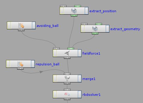
This node lets you define a vector field using attributes on imported geometry, and then use the vector field to “push” dynamics objects.
For each object/voxel to move, the node applies the force of the closest point/voxel in the force geometry.
For example, in the following example, one ball provides the geometry for a “repulsor” field that pushes the other ball away.
Tip
If you want to push RBD objects around using a field extracted from another simulation type, there may be a more optimized and interactive alternative to using a field force.
-
FLIP fluid simulations interact quite efficiently with RBD simulation objets when you enable force feedback.
-
For Pyro simulations, change the solver from Multigrid to PCG and again enable the feedback option.
-
You can use Pump objects to inject velocity in to a FLIP fluid or Pyro/Smoke simulation.
(You can also use a Pump to create a velocity field to feed into a Field Force.)
How to 
| To... | Do this |
|---|---|
|
Set up geometry to shape the field |
In geometry object, create geometry where each point has an attribute containing a vector representing the force direction at that point. The default is to use the Alternatively you can create a vector volume in a geometry object and use that as the source for the force vectors. You can also use a scalar (one value per voxel) volume in which case the field force will use the gradient of the values as the force direction. |
|
Attach the force geometry to the Field Force node |
Create a Field Force node and wire it into the stream of objects/solvers you want the force to affect. Create a (If the geometry you want is already in the DOP network you can grab the
If the source geometry is moving, you also need to attach position data
for the geometry so the force position follows the geometry position.
For an animated object use an
|
|
Choose between speed and accuracy |
The Sampling mode setting gives you a trade-off between speed of the simulation and accuracy of the effect of the force on objects. See the help for Sampling Mode |
Parameters 
Data Options 
Force Attribute
Provides the name of the attribute on the attached geometry subdata which contains the force values. This must be a triple of floats or a vector attribute.
Scale Force
The force attribute value extracted from the geometry is multiplied by this value.
Torque Attribute
Provides the name of the attribute on the attached geometry subdata which contains the torque values. This must be a triple of floats or a vector attribute.
Scale Torque
The torque attribute value extracted from the geometry is multiplied by this value.
Use Max Distance
Turning on this option causes this force to only apply a force or torque if the object is within a given distance of one of the geometry points.
Max Distance
If the nearest point on the geometry is greater than this maximum distance value, then no force or torque is applied. This test is only done if the Use Max Distance option is enabled.
Treat As Wind
Instead of applying a force proportional to the velocity field, apply a drag effect with the velocity field being the rest-velocity. This will cause objects to accelerate until they match velocity field.
Sampling Mode
Controls
Default is the same as Circle.
Point
Samples the nearest point of the force geometry to determine the force to apply to an object. This is the fastest option and is fine for radiating forces and simple objects, where the result is not noticeably different than the more accurate options.
Circle
Samples a cross-section of the force geometry, giving greater fidelity at the cost of slower simulation. If the force geometry has detailed and varying forces, this is a good choice.
For example, if you're sliding colliding RBD objects down a complicated surface in close-up, with subtle sculpted and heavily directed forces, you should use Circle mode.
Sphere
Samples the SDF of the force geometry. This is the slowest option but also the most accurate.
Guide Options 
Show Guide Geometry
Enables the display of guide geometry for this force in the viewport. The guide geometry consists of a series of line segments that start at each point on the force geometry, and indicate the force and torque attribute values.
Guide geometry is only shown when Geometry is used as the subdata. If Vector Field or Scalar Fields are used, guide geometry can be added by using a Vector Field Visualization or Scalar Field Visualization.
Show Force Vectors
Turning on this option causes the force attribute values on the geometry to be displayed as line segments.
Scale Force Vectors
The force attribute values are scaled by this amount before being displayed. Note that the Force Scale parameter is also used to scale the force attribute values for display.
Force Vector Color
The color used to display the force vectors.
Show Torque Vectors
Turning on this option causes the torque attribute values on the geometry to be displayed as line segments.
Scale Torque Vectors
The torque attribute values are scaled by this amount before being displayed. Note that the Torque Scale parameter is also used to scale the torque attribute values for display.
Torque Vector Color
Controls the color used to display the torque vectors.
Sampling Mode
Controls how the force is sampled over space. The behavior will vary depending on the solver. Fluid solvers will always sample per-voxel, but RBD solvers can switch between sampling only the centroid, only the surface, or the entire volume.
Default
Each force type has its own idea of the optimal sampling mode. For uniform forces, for example, only one sample is taken, the equivalent of Point. But with a Field Force that is expected to vary over space, the Sphere sampling mode is the default when Treat as Wind is false, otherwise the Circle sampling mode is used.
Point
Perform a single force evaluation at the center of the object, treating this one value as a constant force for the object. This is the most efficient approach but does not allow for any nuances, for example, of an off-center fan causing an object to start spinning.
Circle
Perform a force evaluation on the surface of the object. This is useful for forces such as wind that one wants to apply non-uniformally depending on the orientation of the object.
Sphere
Perform a force evaluation throughout the volume of the object. This is useful for forces which you want to respect the shape of the object. The number of samples is proportional to the SDF resolution of RBD Objects, however, so can get very expensive.
Parameter Operations
Each data option parameter has an associated menu which specifies how that parameter operates.
Use Default
Use the value from the Default Operation menu.
Set Initial
Set the value of this parameter only when this data is created. On all subsequent timesteps, the value of this parameter is not altered. This is useful for setting up initial conditions like position and velocity.
Set Always
Always set the value of this parameter. This is useful when specific keyframed values are required over time. This could be used to keyframe the position of an object over time, or to cause the geometry from a SOP to be refetched at each timestep if the geometry is deforming.
You can also use this setting in
conjunction with the local variables for a parameter value to
modify a value over time. For example, in the X Position, an
expression like $tx + 0.1 would cause the object to
move 0.1 units to the right on each timestep.
Set Never
Do not ever set the value of this parameter. This option is most useful when using this node to modify an existing piece of data connected through the first input.
For example, an ![]() RBD State
DOP may want to animate just the mass of an
object, and nothing else. The Set Never option could be used
on all parameters except for Mass, which would use Set
Always.
RBD State
DOP may want to animate just the mass of an
object, and nothing else. The Set Never option could be used
on all parameters except for Mass, which would use Set
Always.
Default Operation
For any parameters with their Operation menu set to Use Default, this parameter controls what operation is used.
This parameter has the same menu options and meanings as the Parameter Operations menus, but without the Use Default choice.
Data Sharing
Controls the way in which the data created by this node is shared among multiple objects in the simulation.
Data sharing can greatly reduce the memory footprint of a simulation, but at the expense of requiring all objects to have exactly the same data associated with them.
Share Data Across All Time
This node only creates a single piece of data for the whole simulation. This data is created the first time it is needed, so any expressions will be evaluated only for the first object.
All subsequent objects will have the data attached with the same values that were calculated from the expressions for the first object. It is important to note that expressions are not stored with the data, so they cannot be evaluated after the data is created.
Expressions are evaluated by the DOP node before
creating the data. Expressions involving time will also only be
evaluated when this single piece of data is created. This option
is appropriate for data that does not change over time, and is
the same for all objects, such as a ![]() Gravity
DOP.
Gravity
DOP.
Share Data In One Timestep
A new piece of data is created for each timestep in the simulation. Within a timestep though, all objects have the same data attached to them. So expressions involving time will cause this data to animate over time, but expressions involving the object will only evaluate for the first object to which the data is attached.
This option is appropriate for data that changes
over time, but is the same for all objects such as a ![]() Fan Force
DOP, where the fan may move or rotate over time.
Fan Force
DOP, where the fan may move or rotate over time.
Activation
Determines if this node should do anything on a given timestep and for a particular object. If this parameter is an expression, it is evaluated for each object (even if data sharing is turned on).
If it evaluates to a non-zero value, then the data is attached to that object. If it evaluates to zero, no data is attached, and data previously attached by this node is removed.
Group
When an object connector is attached to the first input of this node, this parameter can be used to choose a subset of those objects to be affected by this node.
Data Name
Indicates the name that should be used to attach the data to an object or other piece of data. If the Data Name contains a “/” (or several), that indicates traversing inside subdata.
For example, if the ![]() Fan Force DOP has the default Data Name
“Forces/Fan”. This attaches the data with the name “Fan” to an
existing piece of data named “Forces”. If no data named “Forces”
exists, a simple piece of container data is created to hold the
“Fan” subdata.
Fan Force DOP has the default Data Name
“Forces/Fan”. This attaches the data with the name “Fan” to an
existing piece of data named “Forces”. If no data named “Forces”
exists, a simple piece of container data is created to hold the
“Fan” subdata.
Different pieces of data have different requirements on what names should be used for them. Except in very rare situations, the default value should be used. Some exceptions are described with particular pieces of data or with solvers that make use of some particular type of data.
Unique Data Name
Turning on this parameter modifies the Data Name parameter value to ensure that the data created by this node is attached with a unique name so it will not overwrite any existing data.
With this parameter turned off, attaching two pieces of data with the same name will cause the second one to replace the first. There are situations where each type of behavior is desirable.
If an object
needs to have several ![]() Fan Forces blowing on it, it is
much easier to use the Unique Data Name feature to ensure that
each fan does not overwrite a previous fan rather than trying to
change the Data Name of each fan individually to avoid
conflicts.
Fan Forces blowing on it, it is
much easier to use the Unique Data Name feature to ensure that
each fan does not overwrite a previous fan rather than trying to
change the Data Name of each fan individually to avoid
conflicts.
On the other hand, if an object is known to have ![]() RBD
State data already attached to it, leaving this
option turned off will allow some new
RBD
State data already attached to it, leaving this
option turned off will allow some new ![]() RBD State
data to overwrite the existing data.
RBD State
data to overwrite the existing data.
Inputs 
First Input
This optional input can be used to control which simulation objects are modified by this node. Any objects connected through this input and which match the Group parameter field will be modified.
If this input is not connected, this node can be used in conjunction with an Apply Data node, or can be used as an input to another data node.
All Other Inputs
If this node has more input connectors, other data nodes can be attached to act as modifiers for the data created by this node.
The specific types of subdata that are meaningful vary from node to
node. Click ![]() an input connector to see a list of available
data nodes that can be meaningfully attached.
an input connector to see a list of available
data nodes that can be meaningfully attached.
Outputs 
First Output
The operation of this output depends on what inputs are connected to this node. If an object stream is input to this node, the output is also an object stream containing the same objects as the input (but with the data from this node attached).
If no object stream is
connected to this node, the output is a data output. This data
output can be connected to an ![]() Apply Data DOP,
or connected directly to a data input of another data node, to
attach the data from this node to an object or another piece of
data.
Apply Data DOP,
or connected directly to a data input of another data node, to
attach the data from this node to an object or another piece of
data.
Locals 
channelname
This DOP node defines a local variable for each channel and parameter on the Data Options page, with the same name as the channel. So for example, the node may have channels for Position (positionx, positiony, positionz) and a parameter for an object name (objectname).
Then there will also be local variables with the names positionx, positiony, positionz, and objectname. These variables will evaluate to the previous value for that parameter.
This previous value is always stored as part of the data attached to the object being processed. This is essentially a shortcut for a dopfield expression like:
dopfield($DOPNET, $OBJID, dataName, "Options", 0, channelname)
If the data does not already exist, then a value of zero or an empty string will be returned.
DATACT
This value is the simulation time (see variable ST) at which the current data was created. This value may not be the same as the current simulation time if this node is modifying existing data, rather than creating new data.
DATACF
This value is the simulation frame (see variable SF) at which the current data was created. This value may not be the same as the current simulation frame if this node is modifying existing data, rather than creating new data.
RELNAME
This value will be set only when data is being attached to a relationship (such as when Constraint Anchor DOP is connected to the second, third, of fourth inputs of a Constraint DOP).
In this case, this value is set to the name of the relationship to which the data is being attached.
RELOBJIDS
This value will be set only when data is being attached to a relationship (such as when Constraint Anchor DOP is connected to the second, third, of fourth inputs of a Constraint DOP).
In this case, this value is set to a string that is a space separated list of the object identifiers for all the Affected Objects of the relationship to which the data is being attached.
RELOBJNAMES
This value will be set only when data is being attached to a relationship (such as when Constraint Anchor DOP is connected to the second, third, of fourth inputs of a Constraint DOP).
In this case, this value is set to a string that is a space separated list of the names of all the Affected Objects of the relationship to which the data is being attached.
RELAFFOBJIDS
This value will be set only when data is being attached to a relationship (such as when Constraint Anchor DOP is connected to the second, third, of fourth inputs of a Constraint DOP).
In this case, this value is set to a string that is a space separated list of the object identifiers for all the Affector Objects of the relationship to which the data is being attached.
RELAFFOBJNAMES
This value will be set only when data is being attached to a relationship (such as when Constraint Anchor DOP is connected to the second, third, of fourth inputs of a Constraint DOP).
In this case, this value is set to a string that is a space separated list of the names of all the Affector Objects of the relationship to which the data is being attached.
ST
The simulation time for which the node is being evaluated.
Depending on the settings of the ![]() DOP Network
Offset Time and Scale Time parameters,
this value may not be equal to the current Houdini time
represented by the variable T.
DOP Network
Offset Time and Scale Time parameters,
this value may not be equal to the current Houdini time
represented by the variable T.
ST is guaranteed to have a value of zero at the
start of a simulation, so when testing for the first timestep of a
simulation, it is best to use a test like $ST == 0, rather than
$T == 0 or $FF == 1.
SF
The simulation frame (or more accurately, the simulation time step number) for which the node is being evaluated.
Depending on the settings of the ![]() DOP Network parameters,
this value may not be equal to the current Houdini frame number
represented by the variable F. Instead, it is equal to
the simulation time (ST) divided by the simulation timestep size
(TIMESTEP).
DOP Network parameters,
this value may not be equal to the current Houdini frame number
represented by the variable F. Instead, it is equal to
the simulation time (ST) divided by the simulation timestep size
(TIMESTEP).
TIMESTEP
The size of a simulation timestep. This value is useful for scaling values that are expressed in units per second, but are applied on each timestep.
SFPS
The inverse of the TIMESTEP value. It is the number of timesteps per second of simulation time.
SNOBJ
The number of objects in the simulation. For nodes that
create objects such as the ![]() Empty Object DOP,
SNOBJ increases for each object that is evaluated.
Empty Object DOP,
SNOBJ increases for each object that is evaluated.
A good way to guarantee unique object names is to use an expression
like object_$SNOBJ.
NOBJ
The number of objects that are evaluated by the current node during this timestep. This value is often different from SNOBJ, as many nodes do not process all the objects in a simulation.
NOBJ may return 0 if the node does not
process each object sequentially (such as the ![]() Group
DOP).
Group
DOP).
OBJ
The index of the specific object being processed by the node. This value always runs from zero to NOBJ-1 in a given timestep. It does not identify the current object within the simulation like OBJID or OBJNAME; it only identifies the object’s position in the current order of processing.
This value is useful for generating a
random number for each object, or simply splitting the objects into
two or more groups to be processed in different ways. This value
is -1 if the node does not process objects sequentially (such
as the ![]() Group DOP).
Group DOP).
OBJID
The unique identifier for the object being processed. Every object is assigned an integer value that is unique among all objects in the simulation for all time. Even if an object is deleted, its identifier is never reused. This is very useful in situations where each object needs to be treated differently, for example, to produce a unique random number for each object.
This value is also the best way to look up information on an object using the dopfield expression function.
OBJID is -1 if the node does not process objects
sequentially (such as the ![]() Group DOP).
Group DOP).
ALLOBJIDS
This string contains a space-separated list of the unique object identifiers for every object being processed by the current node.
ALLOBJNAMES
This string contains a space-separated list of the names of every object being processed by the current node.
OBJCT
The simulation time (see variable ST) at which the current object was created.
To check if an object was created
on the current timestep, the expression $ST == $OBJCT should
always be used.
This value is zero if the node does not process
objects sequentially (such as the ![]() Group DOP).
Group DOP).
OBJCF
The simulation frame (see variable SF) at which the current object was created. It is equivalent to using the dopsttoframe expression on the OBJCT variable.
This value is zero if the node does not process objects
sequentially (such as the ![]() Group DOP).
Group DOP).
OBJNAME
A string value containing the name of the object being processed.
Object names are not guaranteed to be unique within a simulation. However, if you name your objects carefully so that they are unique, the object name can be a much easier way to identify an object than the unique object identifier, OBJID.
The object name can
also be used to treat a number of similar objects (with the same
name) as a virtual group. If there are 20 objects named “myobject”,
specifying strcmp($OBJNAME, "myobject") == 0 in the activation field
of a DOP will cause that DOP to operate on only those 20 objects.
This value is the empty string if the node does not process objects
sequentially (such as the ![]() Group DOP).
Group DOP).
DOPNET
A string value containing the full path of the current DOP network. This value is most useful in DOP subnet digital assets where you want to know the path to the DOP network that contains the node.
Note
Most dynamics nodes have local variables with the same names as the
node’s parameters. For example, in a ![]() Position DOP,
you could write the expression:
Position DOP,
you could write the expression:
$tx + 0.1
…to make the object move 0.1 units along the X axis at each timestep.
Examples 
FieldForceSmoke Example for Field Force dynamics node
Extracts the velocity field from a smoke simulation to use as a wind force on a POP simulation.
FromRBD Example for Field Force dynamics node
This example demonstrates how to use another active RBD Object as the source for the Field Force DOP. Two balls bounce inside a cube, one of the balls is set to repel the other according to force values stored on its geometry.
SimpleField Example for Field Force dynamics node
This example demonstrates the use of the Field Force DOP. A group of RBD Objects are passed through a field which at first pulls the together, and then pulls them apart as they advance through the field.